
Abstract
Concentric-track cutting method of a conventional polycrystalline diamond compact bit makes the bit suffer from inadequate rock-penetrating capacity and severely hinders the improvement of rock-breaking efficiency. Nevertheless, cross-track cutting method is already proved to be an effective way to improve the penetrating ability of the bit. Accordingly, a novel rock-breaking tool with tilted rotating axis is put forward in this article. In this research, first, the structural characteristics of the rock-breaking tool with tilted rotating axis are introduced in detail, relation equations of key geometric parameters of the bit are established, and coordinates of the feature points of the cutters are represented. Second, tracks and motion tendency of the cutters in different areas, as well as the bottom-hole coverage pattern, are respectively analyzed, and the influences of different factors on cutter motion are compared. Third, corresponding indoor experiment is conducted to research the influences of revolution/rotation ratio and axis-tilt angle on drilling efficiency, and the rock particles are compared to reveal the rock-breaking mechanism of the tool. This research is intended to provide basic theoretical support for the engineering application of the tool and is of certain referential significance to improving the rock-breaking efficiency in formations of poor drillability.
Keywords
Introduction
Deep and ultra-deep well drilling is a modern technology used for exploration and exploitation of deep-buried oil and gas resources, where the development of drill bit technology plays a particularly important role in increasing the drilling speed and efficiency. Nevertheless, there are several problems: first, most of the rock in deep formation is of poor drillability, where cutters of the bit cannot penetrate in the rock easily, so generally the ideal drilling speed cannot be reached. Second, well-bore sizes in the deep well-sections are usually small, which severely restricts the design freedom of bit structure, is also one of the main technical bottlenecks for developing high-efficiency drill bits.1–3
The polycrystalline diamond compact (PDC) bit is one of the most commonly used rock-breaking tools in oil and gas drilling. For a conventional PDC bit working in ideal condition, the project curve of the cutter-tracks on the bottom-hole is a series of concentric circles, and each cutter moves along its certain track and cut the bottom-hole rock, which can be defined as concentric-track cutting. In this circumstance, the cutter needs a large cutting force to remove the rock, and once the cutter is worn, curvature of the cutting edge will be rapidly increased so that contact stress between the cutter and rock will be sharply deceased, meaning that the penetrating ability of the cutter be significantly decreased.4–7
The cross-track cutting method is a new concept put forward in recent years,8–10 which is able to increase the drilling efficiency of the bit working in deep formation that is of poor drillability. First, cross-track cutting makes the bottom-hole a non-smooth one, which is beneficial to release the interior stress in mesoscopic rock protrusions so as to lower the shear strength of the rock. Second, the rugged bottom-hole pattern enables the cutters to easily penetrate into the rock and generate large volumetric rock debris. Third, compaction effort of the cutter with negative back-rake angle will be effectively relieved, thus preventing the cutters from sliding on the rock. Specifically, as a consensus in the oil and gas drilling industry, when a PDC bit works in compound drilling mode, the rock-breaking efficiency will be obviously increased.11,12 The reason is that the cross-track rock-breaking in compound drilling mode enables the cutters to cut the rock with cross-tracks and to form a mesh-like pattern in the bottom-hole.
Novel rock-breaking tool with cross-track cutting method
Structure scheme of the tool
A cross-track rock-breaking tool with tilted axis (hereinafter referred to as rock-breaking tool or tool) is put forward in this article.13,14 As illustrated in Figure 1, the tool consists of bit assembly and housing assembly, wherein the housing assembly is assembled from a lower housing, a middle housing, and an upper housing. Furthermore, a cardan shaft module, a screw motor module and a bypass-valve module are configured in the housing. For the bit assembly, the bit body, which configured with cutters, is configured on the lower end of the lower housing and a rotational connection between the two parts is formed thereon. However, the bit body is fixed (through key or screw joint) with the lower connector of the cardan shaft module. In this tool, the rotating axis of the bit body is tilted relative to the rotating axis of the lower housing (i.e. the revolving axis of the housing assembly), thus forming an axis-tilt angle. In the drilling process, the revolving of the housing and the rotating of the bit body will be compounded so that the cross-track cutting process will be realized.

Structure scheme of the rock-breaking tool.
The technical core of the rock-breaking tool in this article can be divided into two aspects. First is the angle between the rotating axis of the bit body (hereinafter referred to as the bit axis) and that of the housing; as illustrated in Figure 1, assuming the rotating speed of the housing (hereinafter referred to as the revolving speed) is zero while the rotating speed of the bit body (hereinafter referred to as the rotating speed) is nonzero, cutters on the bit body will simply rotate along the bit axis and the tracks are simply a series of concentric circles. When both the rotating and revolving speeds are nonzero, the tracks of cutters will be a series of complex space curves, which means these tracks will intersect in the space and thus producing the cross-track cutting motion. Second is the rotational connection between the bit body and the screw motor so that the rotating torque of the bit is provided by the tool itself but not driven to rotate by the counterforce of the rock. In other words, the bit body in this tool rotates proactively but not reactively as a conventional cone bit. Obviously, the compound motion of the bit in this tool is mainly determined by its structural parameters (i.e. screw head number, axis tilt, etc.), but not so relevant to the external factors such as lithological change of the formation or the drill-pipe vibration. Thus, the cross-track cutting can be realized in a stable and reliable condition.
Advantages of the tool
As mentioned above, the cross-track cutting method of the rock-breaking tool in this article changes the bottom-hole pattern. As illustrated in Figure 2, since the tracks of cutters intersect with each other, grooves as well as protrusions will be naturally formed in the bottom-hole rock. When a cutter engages a piece of the rock protrusion, the rock material will be easily removed. The rock-breaking mechanism can be stated in two aspects. On one hand, the grooves generated is beneficial to releasing the inner stress of the rock and lowering the shear strength, making it easy to generate through-cracks within the rock and break the rock with large volumetric fracture, thus saving force and power. On the other hand, the rugged bottom-hole pattern makes it easy for cutters penetrating in the rock protrusions, thus increasing the rock-breaking efficiency. Specifically, when the cutters are worn, the advantage will be more obvious compared with a conventional PDC bit:
The compound motion that combined revolving of the housing and rotating of the bit body makes the cutters on the bit body move along the cross-tracks, and the motion is stable and reliable since it is mainly determined by structural parameters of the tool.
The bit body is directly connected with the cardan shaft, which simplifies the bit-screw motor structure, thus improving the safety and lowering the cost of drilling.
When the tool is working, motion of the bit body is non-eccentric, so that in the circumferential direction of the tool, contact between the bit body and the bottom-hole rock is relatively symmetric, lowering the unbalanced force and improving the stability of the tool.
The bit body is a solid part, making it be of high strength and hard to be fractured.
The solid body leaves more space for hydraulic structure designing. Specifically, the solid body makes it possible for the optimal design of multiple-nozzle structure; thus, the rock-carrying capacity and cooling performance of the bit can be improved.
When the tool is working, cutters in the shoulder and gauge area of the bit will cut the rock discontinuously, thus reducing the thermal-wear risk and prolonging the service life of the bit.

The forming of rock debris in (a) concentric-track cutting and (b) cross-track cutting.
Rock-breaking characteristics of the cutters in cross-track cutting condition
In the conditions of parallel-track cutting (of traditional PDC cutters) and cross-track cutting (of the cutters in the novel tool), a series of unit experiments are conducted to research the stress state in rock, the shear slippage features of the rock, the plastic energy consumption, and the load distribution on the cutters, as shown in Figures 3 and 4. Besides, with different crossing angles, rock-breaking process of the cutter is further simulated, 15 wherein the diameter of the cutter is 15.70 mm, the back rake angle is set at 15°, the cutting speed is set at 0.25 m/s, and the cutting depth is set at 2 mm. As for the rock sample in the simulation, the parameters are set as the Beibei limestone, of which the compressive strength is 105.95 MPa, the elasticity modulus is 31.20 GPa, Poisson’s ratio is 0.171, and the yield criterion is selected as Drucker–Prager.

Rock-breaking simulation in cross-track cutting condition: (a) unit experiment of cross-track cutting, (b) stress state on the rock surface in cross-track cutting condition, and (c) fracture process of the rock protrusion in cross-track cutting condition.

Energy consumption comparison between the two cutting conditions (with cutting volume being the same).
According to the experiment and the simulation, conclusions can be made that:
In cross-track cutting condition, a relatively high tensile stress will be generated inside of the rock, so that brittle fracture is more likely to happen in the rock. Compared with parallel-track cutting, the plastic energy consumption in cross-track cutting is 35% less.
The state of rock debris is related to the surface shape and the volumetric stress distribution in the rock. A rugged bottom-hole is more beneficial to generating cracks beneath the rock surface, so that rock material of large volume is more likely to be removed.
Crossing angle between the tracks has a direct influence on the load on the cutter. The load is obviously higher in parallel-track cutting than in the cross-track cutting, especially when the crossing angle is around 60°, the difference is the largest.
Accordingly, conclusions can be made that the rugged bottom-hole profile shaped by cross-track cutting has changed the stress state on the rock surface and lowered the volumetric strength of the rock. As a result, the specific rock-breaking energy is decreased and the rock-breaking efficiency is increased.
Geometry of the bit and motion tracks of the cutters
Relation equation of geometric parameters of the bit
For the rock-breaking tool in this article, the bit axis and the revolving axis are in the same plane, and the plane is defined as the axis plane of the tool. In reference of the related technical literature (the operational mechanics of the rock bit, etc.),16–19 as illustrated in Figure 5, taking point O as the intersection point of the two axes (since the main part of the bit body is spherical, point O is also the center of the sphere in the axis plane), and point O1 as the journal root center, the arm of the journal root center C, which is one of the most important parameters for settling the geometric position of the bit body, should be represented as
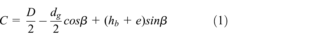
where D diameter of the bit (with cutters);

Geometric parameters of the bit.
According to equation (1), the diameter of the bit can be derived as

However, the surface of the back cone of the bit is set as the rotational gauge surface (while outer surface of the lower housing could be designed as the fixed gauge surface) of the tool; thus, diameter of the bit body

where
Coordinates of the feature points of the cutters in static coordinate system
For rock-breaking tools with a cross-track cutting structure like roller-cone, it is quite convenient to utilize the compound cylindrical coordinate system20–22 to represent the coordinates of the feature points of the cutters. Specifically, the static cylindrical coordinate system OXYZ is established with the revolving axis of the tool being taking as vertical axis OZ. Furthermore, as illustrated in Figure 6, taking the upper end face of the bit body as the principal coordinate plane and the bit axis as the vertical axis

Coordinates of the feature points and load diagram of cutter T(i).
Accordingly, cylindrical coordinates of point
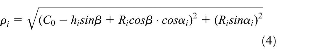


where
Since geometric parameters of the cutters on the bit body are determined, and the position and orientation of the bit body are set, coordinates of the feature points will be settled according to equations (4)–(6). It is the basis for analyzing the cutter motion, cutting tracks, and bottom-hole coverage.
Cutting structure design and kinematic analysis on the bit
On basis of the above analysis, a bit with the diameter of Φ127.00 mm is designed and manufactured as the experimental subject. Specifically, the bit is designed as a steel body bit with six blades, and it is circumferentially fixed with the cardan shaft with double flat-keys while axially locked on the lower housing with bearing rollers. The cutters are in the size of Φ13.44 mm and are distributed on the bit with medium density. As illustrated in Figure 7, the numbers 1–33, respectively, represent the positions of the 33 cutters on the bit.

Designed structure of the bit.
Main factors affecting the motion of the cutting structure include the axis-tilt angle, revolving velocity of the tool, rotating velocity of the bit body, and cutter distribution. In equations (4)–(6),
Besides, it should be noticed that coordinates of the feature point in the static coordinate system could be transformed into Cartesian coordinates, that is

When the angular velocity of the bit rotation is set at 60 r/min, cutter motions in a cycle in different conditions are compared and analyzed.
According to Figure 8, motion track of the cutter is obviously affected by axis-tilt, velocity ratio, and the position of cutters on the bit. It can be observed that:
Tracks of each cutter obviously intersect with itself, and intersection points and angles could be find;
As the locating radius increases, the intersection angles decrease, which means variation of the cutting angle becomes smaller;
As the velocity ratio increases, the number of intersection points increases, while the intersection angle becomes smaller.

Tracks of cutters in different motion conditions: (a) cutter 1#, β = 2.5°, η = 0.44; (b) cutter 2#, β = 3.0°, η = 0.29; and (c) cutter 4#, β = 2.5°, η = 0.67.
Bottom-hole coverage of the tracks shows that cutting structure of the tool makes it possible that cross-tracks completely cover the bottom-hole; as illustrated in Figure 9, especially in the outer shoulder and gauge areas that used to be the most vulnerable in a conventional PDC bit, the bottom-hole is well covered by the cross-tracks and the tracks cross with each other quite regularly in these areas, which is beneficial to improving the overall performance of the bit. Nevertheless, some blank areas could also be found in the bottom-hole, which means these areas are not covered by the tracks so that rock protrusions will be generated in these areas. If the rock protrusions keep growing, the bit body as well as the cutters disposed thereon will finally be harmed, thus decreasing the service life. The existing of blank areas is resulted from the cutter distribution method (i.e. the balanced-cutting-volume method) which is commonly used in conventional PDC bit design. However, when this method is used in the design of the cross-track cutting tool, track coverage condition becomes different, so that the designed balanced-cutting becomes unbalanced on the contrary. Specifically, some areas of the bottom-hole are overly covered, while the others are insufficiently covered. So, to optimize the design of the cutting structure of this tool, a specific cutter distribution method should be developed on basis of related cutting-force research results.

Bottom-hole coverage of the cutter-tracks: (a) β = 2.0°, η = 0.80; (b) β = 3.0°, η = 0.50; and (c) β =5.0°, η = 0.25.
Cutting mechanics research and indoor experiment on the bit
Research on the cutting mechanics of the bit
Based on the load calculation model of the conventional PDC cutter 23 and the rock-breaking characteristics of the cutters in cross-track cutting condition, 15 the load calculation model of the cutter on the novel bit could be derived as

where
On basis of the above calculation model and analyzing with relevant calculation, the curves representing the working load characteristics of the bit are achieved. As shown in Figure 10, the average axial force on the bit is around 95,588 N and the torque is about 3336 N m, where both loads fluctuate obviously, and the fluctuation ranges are, respectively, ±20% and ±7.5%. The maximum lateral force is 1526 N, which is 15.92% of the average axial force. And, the average lateral force is 799 N, which is 8.33% of the average axial force. Apparently, the lateral force on the rock-breaking tool is large enough to affect its working stability. The lateral force is caused by two facts. On one hand, with the existence of axis-tilt angle, the number of cutters contacting the rock is obviously different in different angular areas along the bit axis, and the unbalanced contacting condition will result in a periodic load fluctuation. On the other hand, cutters of the bit are distributed on six straight wing-blades, so that the bit rotation in the bottom-hole will be inevitably affected by polygon effect, and this is consistent with the fluctuation period shown in Figure 10. Accordingly, optimizing the cutter distribution and adopting spiral wing-blades should be considered in bit design to improve the stability of the bit. Besides, related experience shows that a certain periodic impact force exerted on the bit can effectively improving the rock-breaking efficiency, and this is one of the methods to accelerate the drilling speed. So, the rock-breaking tool provided in this article may achieve a better performance in case of improving the rock-breaking efficiency with additional impact force.
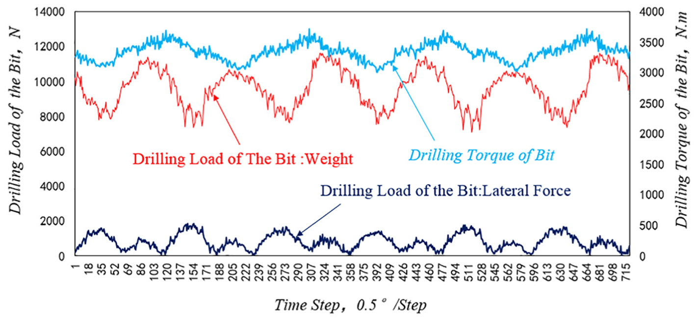
Working load characteristics of the axis-tilted rock-breaking tool.
Indoor experiment on the rock-breaking tool
In order to verify the feasibility and efficiency of the rock-breaking tool, and to provide technical support for the following development of the individualization product, experimental apparatus is designed and manufactured, and indoor experiment is further conducted. Specifically, the driving force of the bit rotation is provided by the “motor-worm gear reducer-cardan shaft-flat key connection” assembly, as part I shown in Figure 11, wherein, the rotating speed is set at 56 r/min. However, driving force of the revolution of the tool is provided by the rotary table, as part II shown in the same figure. For the experimental parameters, the revolving/rotating velocity ratio is, respectively, set as 0, 0.214, 0.357, and 0.571, with the axis tilt as 0°, 1°, 2°, and 3°, the WOB is set at 800 kg, and the rock sample is Nanchong sandstone of which the shear strength is 11.69 MPa.

Experimental apparatus for the rock-breaking tool.
In the experiment, drilling speed of the bit with different velocity ratios and axis-tilt angles are recorded and analyzed. It should be noted that total revolutions are different for the tool under different velocity ratios, so the revolution velocities are uniformized in the following analysis, that is, all the experiment results are uniformized to the equivalent results in the condition of 56 r/min revolution.
In a case study of the experiment on Wusheng sandstone, the experimental data are properly processed and the fitting results are shown in Figures 12–14. As illustrated in the figures, two drilling speed peaks appear on the fitting surface of the results, where the smaller peak appears when the velocity ratio is around 0.34 and the axis-tilt angle is around 1°, and the drilling speed appears to change along a wave curve, of which the maximum value reaches 5.19 m/h. However, the larger peak appears when the velocity ratio is around 0.46 and the axis-tilt angle is around 3°, where the drilling speed appears to increase with the velocity ratio, and the maximum value reaches 5.65 m/h. It should be noted that when the axis-tilt angle is 0°, where the experiment is conducted as a control group without cross-track cutting, the average drilling speed is only 1.56 m/h, indicating that the cross-track cutting method and the novel tool are quite effective to improve the drilling speed.

Bottom-hole patterns in three different rock samples: (a) Wusheng sandstone, (b) Beibei limestone, and (c) Ya’an granite.
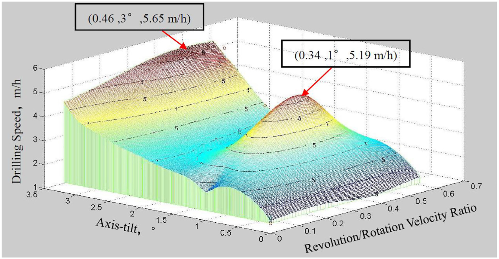
Fitting surface of the drilling speed affected by axis-tilt and velocity ratio.

Variation of drilling speed with the axis-tilt being 1° and 3°.
In the condition that the axis-tilt angle is 3° where the drilling speed reaches its maximum value, drilling speed of the rock-breaking tool drilling in three different rocks are compared, as shown in Figure 15. First, it can be seen that the rock strength has a great influence on the drilling speed—as the rock strength increases, the drilling speed will be accordingly reduced. Second, in the rock with high strength (limestone and granite), the velocity ratio affects the speed greatly. In both the limestone and granite, the drilling speeds reach the maximum values when the velocity ratios are intermediate. Third, the axis-tilt rock-breaking tool performs well in improving the drilling efficiency when drilling in the rock of medium or higher hardness, such as drilling in the limestone.

Drilling speed comparison of the rock-breaking tool in different rock samples.
Moreover, comparison is also made on rock particles collected in the experiment. As shown in Figure 16, the average size of the particles generated by the bit with 0° axis-tilt is obviously smaller than that with 3°, and more volumetric while less powdery rock particles can be found in the latter group.

Status of rock particles collected when the axis-tilt is 0° (left) and 3° (right).
Conclusion
The cross-track rock-breaking tool with tilted rotating axis makes it possible that cutters cut the rock with cross-track motion, which will obviously enhance the penetrating ability of the cutters and improve the working performance of the bit. Moreover, the bit-screw motor structure is simplified in this tool, so that the drilling security is guaranteed while the cost is reduced.
In this tool, the bit body rotates proactively, but not reactively as a conventional cone bit. Obviously, the compound motion of the bit in this tool is mainly determined by its structural parameters, but not so relevant to the external factors such as lithological change of the formation or the drill-pipe vibration. Thus, the cross-track cutting can be realized in a stable and reliable condition. Besides, the central area of the bottom-hole can be well covered by the cross-tracks, which is very important for improving the overall performance of the bit.
Compared with a PDC bit in ideal drilling condition, rate of penetration (ROP) of the tool can be improved up to 3.6 times, and improvement of ROP is obviously related to revolution/rotation ratio and axis-tilt angle. Besides, the rock particles collected are much larger than that of traditional drilling, which significantly lowers the specific power of rock-breaking.
Since the bearing design is limited by the structure of lower housing, it is appropriate to set the axis-tilt angle at 3°; otherwise, too large an angle will weaken the strength of the lower housing. However, the existence of axis-tilt angle will lead to a certain lateral force on the bit and thus causing a periodic fluctuation in drilling process. Accordingly, both cutter distribution and shape of wing-blade should be carefully considered when designing the bit in the tool. Besides, according to the research, when the revolution/rotation velocity ratio is around 0.37, the axis-tilted rock-breaking tool can effectively improve the drilling efficiency in the rock of medium or higher hardness, which should also be considered in the design process.
Footnotes
Handling Editor: Jixiang Yang
Declaration of conflicting interests
The author(s) declared no potential conflicts of interest with respect to the research, authorship, and/or publication of this article.
Funding
The author(s) disclosed receipt of the following financial support for the research, authorship, and/or publication of this article: This work was supported by the National Natural Science Foundation of China (Grant No. 51504209); Special Program for Joint S&T Cooperation Projects of Nanchong City (Project No. NC17SY2001); Open Fund of Key Laboratory of Oil & Gas Equipment, Ministry of Education (Grant No. OGE201403-02); and S&T Innovation Team Project of Southwest Petroleum University (Project No. 2017CXTD07).