
Abstract
Most modern quay cranes operate under the operator’s control. Lifting, lowering, and transporting a container from one platform to another are just some of the actions that a person is responsible for, but the negative consequences of handling can be caused not only by his actions. An error, loading transient instability, or an undervalued environmental factor in the control algorithm can cause a risk to human safety, container, and cargo security. In order to control cargo-handling risk, it is necessary to improve the cargo control systems not only by changing their software, but also by creating additional control algorithms and systems. These systems with programmed control algorithms should be integrated into existing systems to control cargo security and its transfer time. In this article, transient processes and dynamic property of the cargo-handling operation are described and multibody dynamics simulation performed using laboratory prototype of a quay crane. The experimental research performed and integrated autonomous quay crane control algorithm developed with the proposed embedded container swinging control subroutine operated in optimal mode when the control system used PID controller with a feedback including additional PI controller and S-shaped input signal for the analyzed case with the defined parameter set.
Keywords
General introduction
Risk of cargo transportation process and impact of handling/loading procedures
Each year, millions of different types of containers are transshipped in intermodal terminals. Large quay cranes are used as the main transport means for loading cargo from ship to shore and back. Thus loading process is very important stage of intermodal transportation, where necessary measures have to be ensured to achieve high level of physical and technological safety. Incorrect operation of the operator or inappropriate crane control algorithms can not only damage the containers or cargo, but also damage terminal property near the quay crane. Failure to comply with the safety requirements may result in an accident or technical disaster, such as a crane crash or container crash. Each quay crane is unique in its capabilities, so applying common restrictions to all cranes is not appropriate. Each container terminal, based on the needs and possibilities, builds quay cranes whose specifications meet loading needs. The main limitations of the crane in many cases are reflected in their technical characteristics, such as spreader lifting capacity, speed of the trolley, crane travel speed, carriage movement distance, stroke of the boom length and others. In order to ensure cargo safety, it is necessary to monitor and evaluate all parameters limiting the operation of the crane. Therefore, security is achieved through restrictions. 1 It is also necessary to assess critical situations. For example, what happens if one of the carrier ropes is broken, voltage variation hops in the high power supply network, and the impact of the opposite wind will affect the maximal allowable weight lifting process. This is just a small part of the situations that should be evaluated to ensure both the safety of the cargo and the smooth operation of the quay crane. One of the main causes of disasters has been identified as the swinging of the containers. The reasons for the aforementioned swinging are different. Starting from strong wind gusts, operator error, and ending with failure to stabilize the loaded cargo.2–5 This kind of swinging is easy excited because the steel rods connecting load and the spreader of the trolley. Such swinging results increase the time of container transport from point “A” to “B” and decrease cargo safety factor.
In recent years, scientists are increasingly examining how to optimize existing quay cranes due to increased transport flows. One of the most commonly encountered problems in ports is the optimization of container lifting cranes and by means of specific control algorithms.6–10 To date, many different control algorithms have been developed by many authors all around the world, which, under laboratory conditions, solve individual problems of crane control with limited applicability in real life scenarios. However, the need for complex algorithms representing real life scenarios remains the same, focusing not only on individual loading procedures, but also on the entire cargo ship–shore–ship process. Generally, the development of new quay crane control algorithms 11 is associated with the task of solving the problem of container sway during loading procedures. Causes of these sways may vary in each separate case.2–4,12,13 Sometimes swinging is caused by the crane mechanisms (vibrations, motor transients, or uneven surface of the track of the moving devices), but there are cases, where the cause of swinging is unknown. They can be triggered by complex set of forces acting on the container and impact the cargo inside the container. Other scientists2,3,14 are trying to solve the problem of crane load swinging. The investigation is related to the crane-lifting mechanism where the container and crane connected by metal rods. Due to different container weights, wind gusts, and lifting control algorithms, containers often start swinging at the very beginning of its lifting processes. This requires more time for the container to be transported from point “A” to point “B” in the port. Due to changing accelerations, it is likely that the container gets damaged by collision with quay crane structures. As it is known, in the case of strong winds, quay cranes do not usually handle loading operations, which eventually increase loading costs. So, all of this should be avoided by developing more agile technical and software solutions for modernized cranes.14,15
Analysis of crane control algorithms and technologies
In the maritime intermodal terminal, the main controllable unit of the quay crane is a trolley, driven by electric motors moving to the intended position as quickly as possible, while maintaining the minimum load swinging.16,17 Uncontrolled swinging leads to cargo stability and safety problems, especially in container take-off and lowering procedures. The most experienced crane operators are responsible for container handling operations. The latter, relying precisely on the positioning of the container by the quay crane, rely on their visual feedback (carrying out control operations, determined by visual field of view). Such handling procedures can prove to be very complex and time-consuming, especially in extreme situations, where precise positioning depends entirely on operator experience. 18 In any loading procedure, the load can easily swing. If such swinging exceeds the safety limits, swinging must be inhibited or the operator must suspend loading operations until the swinging fall to a safe limit. Complete elimination of such resulting swinging is practically impossible even with the use of modern control technologies, but in specific situations, such swinging can be easily suppressed. This swinging can be influenced by various external factors such as wind, weather changes, or operator actions. 16 This inevitable swinging of cargo often leads to reduced cargo-handling efficiency, container damage, or accidents in the terminal. 19 Moreover, the loading process requires a fast container transport to the required position, but the transport speed is as high as possible, thus the load varies more, thereby aggravating the operation of the operator and the entire transportation process.20,21 Freight fluctuations also affect the operation of an experienced operator and reduce the positioning accuracy of the spreader. In order to achieve a higher positioning accuracy of the crane spreader, it is necessary to install a control system that evaluates the trolley acceleration and the amplitude of swinging. One of the most effective, practically the cheapest and the most effective methods for managing the efficiency and speed of loading is the application of motion profiling methods. However, rapid movement greatly affects the uniformity of movement and causes persistent swinging. Motion control profiling techniques and the search for compromise parameters between the occurrence of motion speed and continuous swinging and their size are one of the main and most complex tasks of the motion profiling, which are solved by means of automatic control systems. 22 In order to increase the transport efficiency, it is necessary to increase the speed of the transportation. Therefore, it is necessary to control sudden changes in acceleration, which results high amplitude vibrations. In literature sudden changes in acceleration are called jerks.
These jerks can be controlled using their limitation rules. Jerks-limited motion profile is the main motion design tool in modern motion control systems. And this is also the optimal solution for body movement control. Loss limitation is used to reduce swinging that arise from the nature of the proclaimed motion process, which can also be optimized. 23 Slip-constrained integration of the motion profile into a trapezoidal speed profile enables control of the speed profile projections to produce a symmetric or asymmetric S-speed profile. The uniformity of motion using the S-shape profile depends on the duration of the tensile force. A longer period of time until the snap reaches the forged value increases the uniformity of the movement of the controlled object, but reduces the efficiency over time. Therefore, in the individual control stages, in order to ensure good S-shaped profile parameters, it is necessary to carry out appropriate experimental studies in order to determine the optimal parameters for the control system. The trapezoidal speed profile is based on the three-phase acceleration trajectory. 24 This type of method is one of the most commonly used motion control technologies applied to quay cranes.24–26 However, the problem of infinite shuffle greatly limits the use of this profile in automated control systems. Three-phase acceleration control reduces overall system control capabilities compared to a more modern S-trajectory speed profile. The S-shaped speed profile is most commonly used to improve movement uniformity. This is done by reducing the amount of peak in the acceleration and deceleration phases.22,26–28 This type of motion profile is based on a seven-phase acceleration trajectory, which is controlled by changing the value of the jerk. The motion limitation controlled by the motion profile effectively reduces the vibrations triggered during the acceleration procedure. First, this type of motion rate profile 23 is used to reduce uncontrolled swinging. Only if motion is not improved efficiently, the latter is combined with modern control technologies such as a PID (Proportional-Integral-Derivative) controller or ambiguous logic. Such use of the speed profile with other control technologies, when the profile is used to form the input signal, also known as input profiling. 17 A great deal of research was devoted to the research of this control technique, in particular, where the input profiling plays a central role16,17,23,29–31 in control techniques. Input profiling reduces vibrations by slightly adjusting the control command through the number of pulses. It generates a two-pulse sequence instead of one, thus obtaining the so-called zero-vibration profiling. When the pulse is properly formed, the subject moves without continuous swinging. One of the main advantages of input profiling in comparison to the feedback control systems is the need for additional sensors to form a control signal. 29
In order to increase the safety of the transported cargo, new methods for modeling the dynamics of the container handling process are being developed. They aim to better simulate system behavior under different loading conditions and factors.32–36 One such research is 3D Dynamic Modeling of the Marine Crane Movement System, presented by scientists Ismail and others. 33 The Lagrangian method was used for calculations. The data collected during the simulation of the dynamical system were collected and analyzed, and the position of the trolley and the angles of the spreader’s tilt were recorded. The results obtained by a researcher are of great significance for the future development of control algorithms for the control system of double spreader quay crane. Jaafar and other scientists 32 developed a nonlinear model of the control system of the quay crane, which explored the factors that influence the capabilities of the system. During the study, the input voltage, cable length, load, and trolley mass were changed. The simulation results of this system indicate that the system response is very sensitive to these combinations of parameters. They have also found that inappropriate parameter selection may be one of the main reasons influencing the swinging of containers and posing problems of cargo security during transportation. Most of the models associated with dynamic control and cargo security issues are presented to address one type of problem. For example, a crane control system with state simulator, 35 in which the dynamic model is created, is intended to solve problems related only to handling operations and positioning in the presence of different wind interruptions. Also, the dynamic model created by another scientist 36 is intended only to simulate the process of lifting heavy loads using floating cranes. In order to increase the automation of quay crane processes, it is necessary to solve problems related to container swinging. 19 Each research carried out in this area brings to the creation of an intelligent control approach and application in real quay cranes as an industrial control tool. Fuzzy logic based control systems do not require very precise mathematical models or details of a controlled object, and the applicability of such systems is relatively simple. 37 However, these control systems do not solve the complex control tasks that are relevant to the control of the quay crane. The application of this modern control tool alone results in insufficiently clear and efficient results in all situations, so that it can be applied in practice. Combined control of fuzzy logic using PID controller could be used as one of the possible solutions for the development of a modern intelligent crane control system.19,38,39 However, the results of recent years show that input profiling together with the PID controller yields promising results.16,17,30 Thus, the quay crane’s control system has been offered in order to realize the concept of an autonomous port. The PID controller is most widely used in the industrial perspective due to its simple structure and stable operation under various conditions. 40 Scientists Liu et al. 19 developed a control system that used fuzzy logic and a PID controller to manage the transport of bridge crane loads. They presented a complete system, and the results of the research that shows that the combination of these modern control technologies yields effective results could possibly be realized in real systems. However, most scientists are confronted with the correct setting of the PID controller in the crane operation. Traditional parameter-matching techniques, such as the test and error method, are one of the easiest ways to reconcile the PID controller, but the results obtained by this method do not guarantee significant and effective results.18,21,41 Another method for controlling the controller is Ziegler–Nichols, 20 which is most widely used because of its simplicity. Depending on the results obtained due to the aggressiveness and excessive fluctuations in the variations, researchers have used other methods to reconcile the parameters of the PID controller.
The most commonly used PID controller coupled with changeable optimization techniques based on parameter selection methods. 42 Some of these are genetic PID parameter selection algorithms for automated crane operations20,42; artificial bee colony algorithms used to reduce sharp spikes or time parameters. 43 Ant colony algorithms also used to optimize nonlinear PID controller parameters. 20 Scientist Jaafar not only analyzed PID controller technologies in crane control, but also applied a wide variety of controller combinations. This scientist proposes a control structure combining PID and PD controls. The PID controller used to position the quay crane trolley, while the PD controller is used to reduce cargo swinging. The control model structure that combines PID and PD controls to monitor different parameters applied across multiple systems. In many cases, the PID controller used to control the position, while the PD controller is used to reduce the swinging that occurs. However, for such a model, it is already necessary to combine the five-parameter values. In the literature, it is often reported that the output of such control model controller uses the x-position and the swinging angle θ.
Problem formulation
In recent years, scientists are increasingly examining quay cranes in order to use the existing resources to manage the constantly growing cargo flow in containers in the world. Industry is lacking the necessary tools to increase crane work efficiency. One of the most commonly encountered problems in the engineering community is the development and application of container lifting crane control algorithms for improving existing crane control systems.1–4,11 In this article, we are discussing the possibilities of improving crane control operations and utilizing the crane potential to manage even the hardest tasks, caused by weather conditions and operators inexperience. Most analyzed control algorithms developed to solve individual problems on-site. Used methods are oriented to single problem solving without the need for complex problem analysis. In this article, we have formulated a complex problem for controlling the loading procedures (ship–shore–ship) by developing integrated autonomous quay crane control algorithm with embedded container swinging control subroutine, operated in optimal mode for the analyzed case with the defined parameter set. We have used PID controller with additional PI with feedback and S-shaped input signal.
The laboratory quay crane Matlab Simulink model was developed where the main parameters for experimental research was used: maximum traveling distance—2.2 m, spreader with container mass mg—7.45 kg, the trolley mass mvž—3 kg, and the maximum spreader with container lifting height—1.9 m.
The important part of container swinging reduction control system is PID controller, which mathematical equation (1) is well known

here: u1(t)—control signal output of PID controller, u2(t)—control signal output of PI controller, u(t)—combined control signal, e1(t)—error signal of main control loop, e2(t)—error signal of auxiliary control loop, Kp1—proportional coefficient of PID controller, Ki1—integral coefficient of PID controller, Kd1—differential coefficient of PID controller, Kp2—proportional coefficient of PI controller, Ki2—integral coefficient of PI controller, kfb1—trolley velocity sensor transfer coefficient, kfb2—spreader velocity sensor transfer coefficient, and g(t)—input signal proportional to the reference trolley vmax velocity.
The S-shaped velocity profile (see Figure 2) was used as input signal for experimental and modeling and could be described (equations (2)–(7)).

General block diagram of control system. ttr is the trolley traveling time, and the reference block output gref(t) is equal to zero because the spreader oscillation velocity must be reduced to zero.
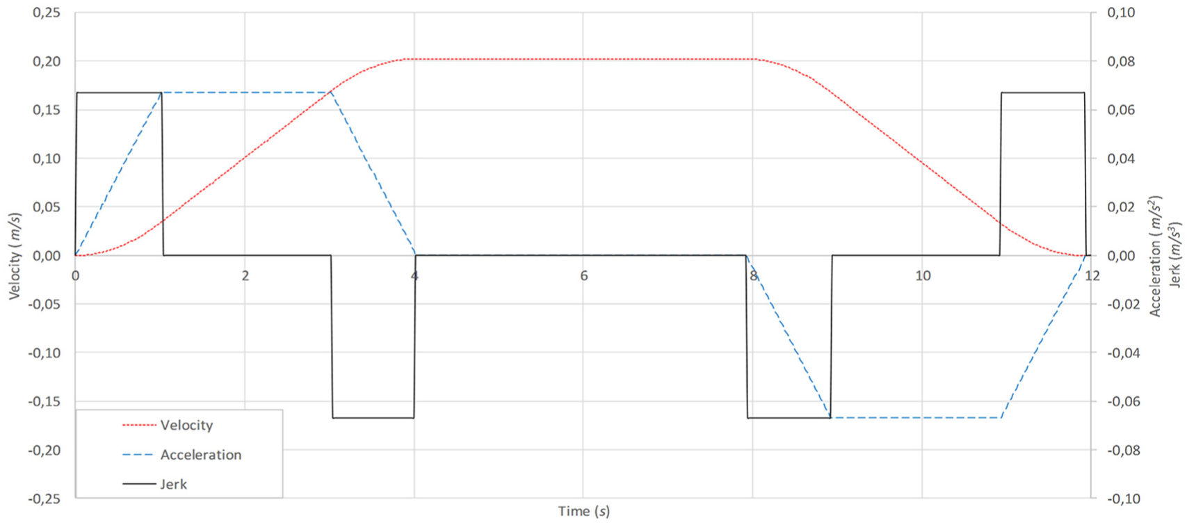
S-shape velocity profile: velocity (red dotted), acceleration (blue dashed), and jerk (black solid).
The trolley acceleration was calculated

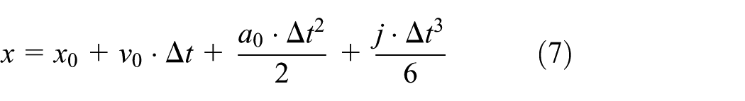
The maximum possible acceleration of the S-shape speed profile was calculated as

here j%—the initial tangency value was selected which is equal to 50% of the original value. The breaking constant was calculated as
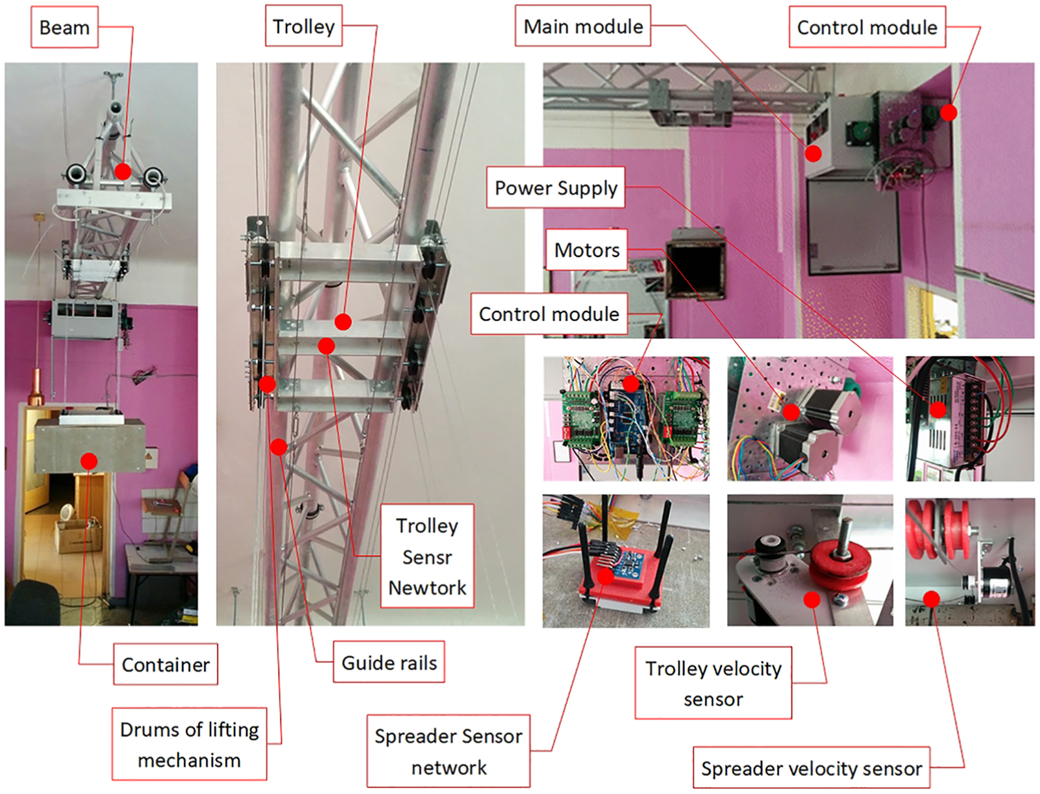
Jerk’s value depends on the phase of the S-profile and it can be 0, j, and –j. The quay crane control system recalculated the acceleration a, speed v, and position x within each time interval


here: Δt is the time interval related to converter sample rate, a0 is the acceleration value where initial value is 0 because the trolley starts moving from 0 acceleration and each calculation step after Δt the a0 value is recalculated by equaling a0 = a by previous calculation step (from equation (5)), and v0 is the value of the previous speed where initial value is 0 because the trolley starts moving from 0 velocity and each calculation step after Δt the v0 value is recalculated by equaling v0 = v by previous calculation step (from equation (6)). x0 is the value of the previous position, where initial value is 0 because the trolley starts moving from 0 position and each calculation step after Δt the x0 value is recalculated by equaling x0 = x by previous calculation step (from equation (7)), and vmax was determined using real crane parameters and reduced up to laboratory crane prototype resulting 0.2 m/s.
The design variables of PID and PI controller that need to be determined are as follows: for PID controller in main control loop—Kp1, Ki1, and Kd1, and for additional PI controller in auxiliary control loop—Kp2 and Ki2.
Development of crane’s control system prototype
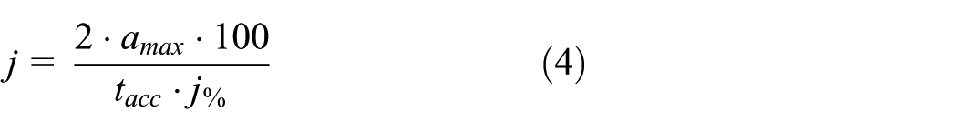
To date, many different control algorithms were developed that solve individual problems,2,6–8 but there is still a need for the development of complex algorithms that are oriented not only to individual loading procedures but also to a full ship–shore–ship stevedoring cycle. Frequently, the creation of new quay crane control algorithms9,44 is associated with solving problems, which attempt to solve the problem of container swinging,45,46 the causes of which can occur in each case.10,11 Sometimes swinging caused by the mechanisms of the crane itself, such as the engine, or uneven track surfaces on which the devices move. However, there are cases in which the causes of swinging are unknown—they can be caused by a complex set of effects on the container area or even within the container itself. The basic structure of the developed laboratory prototype is presented in Figure 3.
The main system components of quay crane prototype.
The laboratory crane fixed by a relatively flexible connection to the laboratory ceiling. The lower arms of the boom are facing the guideways for the horizontal trolley movement. The trolley top is equipped with a sensor net for trolley movements and position measurement. In the lower part, the pulleys used for lifting a spreader holder. A sensor network also installed at the top of the spreader, recording its swing angle, speed, and position. The spreader and the lifting mechanism controlled through the main unit, which is equipped with transmission gear and an electronic automatic control system installed. This system consists of a control module, motors, trolley, and clamp speed sensors and a power supply. After performing virtual checks of the quay crane–lifting mechanism and spreader system and constructing a laboratory prototype for experimental research, it was necessary to simulate the quay crane’s control system in a computer environment. The control task signal programmed using a speed change profile was selected through experimental and theoretical studies. Based on the analysis of the scientific literature and the evaluation of the effectiveness of the PID controller in this type of crane control systems, it was decided, first, to select the appropriate speed profile for the input, which was combined with the PID controller for the control of the quay crane transportation process. Experimental studies have been carried out to select the input forecourt method, which compared the efficiency of two speed profiles to evaluate the container’s continuous swinging. In order to compare these profiles, mathematical calculations were carried out with respect to crane speed, lifting power, and other characteristics and setting similar acceleration and deceleration parameters. As the input signal shaping is one of the important actions for the reduction of the initial sway of the container, the S-shaping of the input signal is analyzed. The initial acceleration and deceleration settings in both above-mentioned cases of the Y-axis are tacc = 4 s, which corresponds to the synchronous speed profile.
The calculations using above-mentioned equations (equations (2)–(7)) are implemented in the Arduino Control Module and Simulink modeling. During the experiment, the container was raised to a height of 1.52 m (Z-axis) relative to the horizontal reference plane (this plane is kept in the experimental stand’s floor), and transported by Y-axis at 1.61 m and eventually lowered to 0.58 m (Z-axis). This transportation case has been applied to both speed profiles. When comparing the velocity of the container and the velocity profile in both cases on the Y-axis (see Figure 4), the residual oscillations at the end of the transportation process is the same. Although in individual cases, the use of S-profiles in different systems shows significantly smaller load swinging, due to the complexity of the crane system in which the load is suspended on the ropes, the results do not provide the result of the desired oscillation suppression. Scientists KH Rew et al. 22 adapted the S-shaped speed profile to the robot manipulator when a boom is mounted with a rigid connection. During case study, the S-shaped speed profile was adapted to the quay crane spreader for controlling cargo variations when the spreader is connected to the trolley with a flexible connection. As in the case of KH Rew et al., 22 the steeper movement of the trolley has been realized, but the continued swinging in the unassembled spreader holder have remained and are similar in both cases.

Cargo oscillation comparison using trapezoidal and S-shaped velocity profile.
Depending on the results of other researchers described in the first section, it can be concluded that such complex control system requires combined control technologies. Regarding the control signal u(t), the plant consists of converter, motor, and crane with cargo models. The converter performs conversion of control signal to PWM (pulse-width modulation) signal that afterwards generates the motor phase voltages UA and UB (equation (8))

The generation of voltages UA and UB are implemented in using PWM signal modulation (presented in Figure 5). These voltages were used as an input signals for the stepper motor, used in laboratory prototype, which could be described using system of equations (9):


Block diagram of lifting mechanism mechanical subsystem. Mv.red—gear reduced motor torque, Md—dynamic torque of plant, avž—trolley linear acceleration, εg—angular acceleration of spreader, and s—Laplace operator.
here: Km—torque constant of stepper motor, iA and iB—stepper motor coil current, eA and eB—electromotive force of stepper motor, Rm—magnetization resistor, Nr—stepper motor tooth per pole, θ—single-step rotation angle, Mbt—internal braking torque, R—winding resistance, L—winding inductance, and UA and UB—A and B phase winding voltages.
Therefore, the use of the S-shaped profile, as part of a single control system, can be used as reference signal of control system. A comprehensive mathematical model (equation (10)) was also developed

Based on the crane-lifting mechanism and spreader holder control system, the model was transformed in the Matlab Simulink environment structure (see Figure 5).
Here, η—the efficiency of the mechanical transmission, φg—the angle of the spreader (gripper) swinging, ωg—the angular velocity of the spreader (gripper) swing, svž—trolley displacement, vvž—trolley speed, mg—the mass of the spreader with the load, mvž—the weight of the trolley, L—the length of the cable rods, Rdr—drum radius, Jb—moment of drum inertia, Jv—moment of inertia of electric motor, U—reduction gear ratio, Mfr—friction moment, Mv—engine moment, and indices: vž—trolley, g—spreader (gripper), s—pulley, v—motor, and B—motor rotation damping.
In addition, in this model, a computational structure was developed for calculating linear kinematic parameters of cargo, linear load variation, speed, and displacement. The crane-lifting mechanism and the trolley’s mechanical subsystem unit consists of two inputs and 12 exits for monitoring the system. Outputs describe the kinematic characteristics of the trolley and the load. Inputs are provided for the momentum of the frictional force and the torque input. The Matlab Simulink stepper motor unit (model) was simulated by compiling a mathematical model according to the technical characteristics of the laboratory physical model. Low-power asynchronous motors were used in the prototype. However, stepper motors were used to create a control system for the new gantry and lifting mechanisms for laboratory prototype. The available material resources influenced their use. The stepper motor model consists of three inputs and one output. A PWM signal from the PWM generator block is fed into the input of the controllable power converter subsystem unit, and the unit generates a signal for the stepper motor to operate in half-step mode, thereby increasing positioning accuracy. An PWM generator block is depicted in Figure 6.

Pulse-width modulation generator block internal structure.
The purpose of this Simulink unit is to realize the internal function of the Arduino mathematical models, which is converted from the frequency that is proportional to the Y-axis of the crane trolley with the load movement of the linear velocity of the crane to the PWM signal for the input of the power converter unit. This frequency change is realized structurally. The Simulink in the mathematical model also has two additional blocks—one for changing the speed signal to the set frequency that feds PWM generator input and the other block is for the S-shaped velocity profile set-top square signal formation block.
Simulation results and discussion
The Simulink model has been tested by feeding the S-profile inlet profile when the crane trolley control system is open-ended (without feedback) and a crane trolley with a load of 1.9 m in length runs at a speed of 0.2 m/s. The resulting graph is shown in Figure 7—where the S-shaped profile signal is green, the speed of the crane trolley is a blue line, and the linear velocity of the cargo swinging relative to the cargo hanging point is red. As shown in Figure 7, in addition to the control trolley, the response lags the reference signal in the dynamic mode and has a dynamic error. Due to the absence of a PID controller and feedback, there is also a static error, which in this case is equal to 1.3% and does not have a significant effect on the system for operation. The load-swinging rate reaches almost 0.15 m/s, amplitude variation during the period is 7.7%, and the frequency is 0.374 Hz. These experiments are the starting point for setting the PID controller parameters. This mathematical Simulink model was designed to determine the parameters of the PID controller, which minimize load swinging in the trolley. Many literature reviews were made on this topic, and many methods were examined for adjusting the PID controller. In addition, some finding were also applied to our experimental test-bed, taking into account the complexity of the system and the hanging load, whose swinging is minimized. In our example, the research findings do not produce the desired results, and it was decided to combine the controller empirical and experimental results, by determining the controller coefficients resulting minimal swinging during the grabbing and the transportation procedures.

S-shape velocity profile (green), trolley velocity (blue), and spreader oscillation velocity (red) graphs.
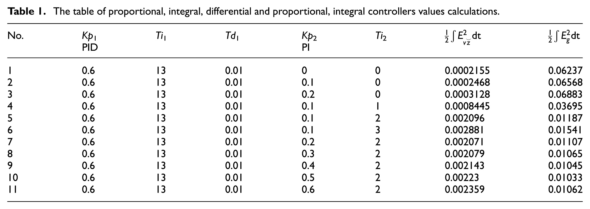
It is difficult to reconcile the parameters of this controller in a physical laboratory prototype due to technical limitations and the possible failure of prototype in case of inappropriate parameters. Therefore, the parameters of the PID and PI controllers were prepared using the mathematical model of Matlab Simulink by utilizing the method of minimization using the integral criterion of the square error of trolley velocity (Evž = vvž– v, where v are from equation (6)) and spreader oscillation velocity (Eg = 0 –vg). The integral criterion of the square error mathematical formulation are presented in Table 1, accordingly seventh and eighth columns. The procedure of PID and PI controllers parameters determination was divided in two steps. First, the PID controller parameters were determined without auxiliary feedback to find the minimum value of integral square error of trolley velocity and was obtained by modeling (first line of Table 1) for initial calculations. Then the auxiliary feedback was activated and using MatLab simulation, the PI controller parameters were determined, calculating the minimum integral criterion of the square error of spreader oscillation velocity. The first step of controller (PID) parameter estimation was carried out without feedback (crane trolley velocity and load variation linear velocity). The proportional part is Kp1, the integral part is Ti1, and the coefficient of the differential part is Td1 (presented in Table 1). Initial approximation sets the parameters of the PID controller when there is only a crane trolley’s speed feedback in the system. In the second simulation, the minimum square error tolerance has been set, but this is explained by the fact that the trolley does not reach the set speed (0.2 m/s) due to low amplification and therefore, by increasing the proportional part of Kp1, this deviation decreases. Therefore, Kp1 = 0.2 was selected for another search and the PID controller integral component of the factor was determined. This step is used to minimize the steady state error of the trolley’s speed, as increasing the coefficient of the integrative component increases the system response speed, and therefore the load swinging is much higher. According to the simulation results with only one feedback, the following parameters of the PID controller were obtained: Kp1 = 0.6, Ki1 = 13, and Kd1 = 0.01. Using these parameters, the transition process of crane trolley and load variation rates is presented, which is shown in Figure 8.
The table of proportional, integral, differential and proportional, integral controllers values calculations.

S-shape velocity profile (green), trolley velocity (blue), and spreader oscillation velocity (red) graphs with PID controller and one feedback.
The second step was performed for the auxiliary feedback control loop with PI controller designed to suppress container swinging (shown in Table 1). According to the results, it was determined that the additional PI system for reducing the intensity of cargo volatility has a higher error (Table 1, Results 8-11) only with the proportional controller (Table 1, Results 8-11). This is a result of the integral part of PI controller, and the square error is increasing by increasing the Kp2 coefficient.
According to the data of Table 1 and modeling results, the following PID and PI coefficients were chosen: PID: Kp1 = 0.6, Ki1 = 13, Kd1 = 0.01, and additional PI controller: Kp2 = 0.2 and Ki2 = 2. Selected seventh case is based on the trolley’s integral square error minimal value in the PID and PI control system, and the square integral error of the load swinging varies from this value every 3%. These control parameters are the initial data of the PID and PI controller for experimental evaluation.
Conclusion
In this article, an integrated autonomous quay crane control algorithm was developed with the proposed embedded container swinging control subroutine, operated in optimal mode when the control system used PID (set parameters: Kp1 = 0.6, Ki1 = 13, and Kd1 = 0.01) controller with additional PI (set parameters: Kp2 = 0.2 and Ki2 = 2) with feedback and S-shaped signal. These PID and PI controllers’ parameters were determined by finding the minimum integral criterion of the square error (Table 1) of spreader traveling speed. These optimal parameters are suitable for case studied in the article; therefore, system parameter changes the PID and PI parameters should vary and be adaptable, and such investigation is planned for future research. The experimental laboratory physical model was designed to verify the theoretical and simulation findings. Results suggest that during loading process using the S-shaped velocity profile in dynamic mode as control system input provides a possibility to obtain a most suitable solution for the transport modes of a specific container. The results of comparative and experimental studies show that proposed autonomous quay crane’s control algorithm, with a PI subsystem for decreasing container swinging during loading, can be used to accelerate the handling process.
Footnotes
Handling Editor: Xiangwei Bu
Declaration of conflicting interests
The author(s) declared no potential conflicts of interest with respect to the research, authorship, and/or publication of this article.
Funding
The author(s) disclosed receipt of the following financial support for the research, authorship, and/or publication of this article: This research was funded by the European Regional Development Fund according to the supported activity “Research Projects Implemented by World-Class Researcher Groups” under Measure No. 01.2.2-LMT-K-718-01-0081.