
Abstract
The noise characteristic of an entire single-cylinder gasoline engine was tested through acoustic spectral and intensity analyses to solve its abnormal noise problem in idling condition. Then, the abnormal noises were identified as piston impact noises caused by the anomalous dynamic performance of the piston mechanism. A piston multibody dynamic model was established on the basis of the key performance and the structure parameters of the piston to eliminate the abnormal noise. Then, the piston dynamic performance was improved by optimizing the piston structures. Analysis results showed that the lateral force, secondary kinetic energy, and friction power loss of the piston were reduced by approximately 51.3%, 40.2%, and 31.8%, respectively. Finally, the acoustic verification tests were implemented on the basis of the original engine when the optimized sample was manufactured and installed in the engine. The results showed that the abnormal noise was eliminated and the overall sound pressure level of the engine was reduced by 2.5 dB(A) in idling condition. Meanwhile, the subjective evaluation results showed that the sound quality was obviously improved. The dynamic performance of the piston could be improved by optimizing the piston structure to reduce the impact noise.
Keywords
Introduction
The abnormal noise problem of an engine seriously affects the subjective feeling of comfort of passengers. As the main moving part of the engine, the piston possesses numerous contact surfaces and complicated running environments. Therefore, frictions and impacts, which seriously affect the vibro-acoustic characteristics of the engine, can be easily generated. Thus, the piston becomes an important optimization objective and can control the noise, vibration and harshness (NVH) performance of the engine. Currently, studies of piston dynamic performance have already been conducted to optimize engine NVH performance control.
The impacts from piston to cylinder liner are generally the maximal mechanical noise sources of the internal combustion engine. With the periodical changes of the role of gas pressure and inertial force in the piston, the piston exhibits minute translational motion and rotation, except for reciprocating motion along the axial direction of the cylinder liner, because of the gap between piston and cylinder liner. The piston’s thrust on the cylinder liner changes from both sides repeatedly, thereby generating the continuous impacts from piston to cylinder. This type of piston motion is called secondary kinetic motion. 1
In this research area, Koizumi et al. 2 analyzed the piston secondary kinetic motion of small gasoline engine and established the mathematical model used to analyze piston impact force, which proved that the research on piston secondary kinetic motion could predict impact force. Kim 3 established the piston secondary kinetic motion model with hydrodynamic lubrication submodel, by which the influences of pin offset, cylinder clearance, and oil viscosity on the lubricating property and piston secondary kinetic motion were analyzed. Mansouri and Wong 4 established the piston secondary kinetic motion model considering the lubricating conditions of fluid lubrication, boundary lubrication, and mixture lubrication. Taylor and Evans 5 conducted experimental studies of piston secondary kinetic motion. Sato et al. 6 analyzed and optimized the frictions between piston and cylinder liner by analyzing the piston secondary kinetic motion model; friction loss was reduced by 2%. McClure and Tian 7 established an analysis model of piston secondary kinetic motion that ignores the hydrodynamic lubrication and considers the deformation of piston and cylinder liner, by which the influences of engine speed and cylinder liner deformation on piston secondary kinetic motion were analyzed. Bueno and Raminelli 8 investigated the influence of piston secondary kinetic motion on cylinder liner cavitation corrosion of diesel engine. McFadden and Turnbull 9 explored piston secondary kinetic motion in dry friction and fluid lubrication conditions on the basis of the piston secondary kinetic motion model. Murakami et al. 10 established an analysis model of piston secondary kinetic motion on the basis of flexible multibody dynamic theory, by which the piston secondary kinetic motion and the stresses on piston skirt were simulated. McFadden and Turnbull 11 considered the influence of the piston profile on piston secondary kinetic motion and oil film pressure of the skirt. In the research area of piston impact noise and piston structure design, Cho et al. 12 simulated piston secondary kinetic motion on the basis of the piston dynamic equations, which were obtained from the combination of the motion and moment equations of the skirt. Zheng et al. 13 analyzed the ship hull vibrations caused by piston impacts and vertical inertial forces of rotating gear. Nayak et al. 14 successfully predicted the vibrations and noises of the engine caused by the piston impacts by use of the AVL software. Ei Badaoui et al. 15 quantized the ratio of mechanical noise of a diesel at the top dead center (TDC) caused by piston impacts and combustion noises using the finite element method on the basis of the convolution models of nonstationary systems. Chai and Jiang 16 established the piston models of different pin offsets to analyze the impacts on piston caused by positive or negative offsets. Liu 17 , Cheng 18 , Liu, 19 and Ren 20 examined the influence of different piston structures on dynamic performance.
Existing research covers multibody dynamic analysis, structure and performance optimization, and model research but does not involve the piston structure design method considering the NVH performance of the entire machine. On this basis, noise source identification and control-related research are conducted to solve the problem of abnormal noise in idling condition of a single-cylinder gasoline engine. This study aims to identify the noise sources and characteristics by means of noise spectrum and sound intensity analyses. The optimization design method of the piston structure is presented to eliminate the abnormal noise and improve the sound quality of the engine.
Problem statement
A single-cylinder gasoline engine possesses abnormal noise with medium frequency and continuity characteristics, which particularly appear prominently in idling condition. With the increase in the speed and load of the engine, the abnormal noise is gradually eliminated or masked by the engine combustion noise, mechanical noise, and other work noise. The research approach to eliminate the noise is proposed. First, on the basis of the semi-anechoic chamber of the engine, the spectral characteristics of the abnormal noise are identified in accordance with the acoustic spectrum analysis of the idling condition. Furthermore, the noise source position of the specified spectrum is determined by sound intensity analysis. Then, the most important evaluation parameters and key structure factors that significantly affect the dynamic performance of the engine are determined by the orthogonal array method based on the multibody dynamic model. Meanwhile, the dynamic performance of the components that cause the abnormal noise is promoted by optimizing the structures of the key components. Finally, the optimized sample is manufactured and the verification test is conducted on the basis of the original engine. The effectiveness of the optimized design is verified by the acoustic characteristic test and subjective evaluation of the entire engine.
Diagnosis and identification of noise sources
On the basis of the previously presented characteristics of the abnormal noise, the sources of the abnormal noise are diagnosed and identified by subjectively evaluating the acoustic spectrum characteristics and locating the source.
Acoustic spectrum characteristics
The spectrum characteristics of the abnormal noise in idling condition are observed in a semi-anechoic chamber. The test equipment mainly includes an LMS SCADAS data acquisition system and a few acoustic microphones. The measuring point locations and test methods follow the standards of ISO 6798:1995 21 “Reciprocating internal combustion engines-measurement of emitted airborne noise-engineering method and survey method” and QC/T 70-2014 22 “Measurement method of acoustic noise for motorcycles and engines.”Figure 1 shows the test equipment and the specific acoustic measuring points. The measuring point on the left side near the sprocket cover lid is defined as L, whereas the measuring point on the right side near the spark plug is defined as R. During the measurement, the pressure level of the ambient noise is maintained at approximately 10 dB(A) lower than that of the tested noise.

Data acquisition system and arrangement of measuring points.
The idle speed of the single-cylinder gasoline engine is 1500 r/min. Figure 2 shows the steady noise spectrum characteristics in measuring points L and R in idling condition. Two suspicious spectra are detected in point L (defined as L1 and L2), and four suspicious spectra are detected in point R (defined as R1–R4). Using the sound playback technology, the abnormal noise spectra are confirmed as L1, R1, and R2 by filtering the suspicious spectra successively.

Steady noise spectrum characteristics in idling condition: (a) measuring point L and (b) measuring point R.
Acoustic intensity characteristics
After obtaining the spectrum characteristics of the abnormal noise, the sources of the suspicious spectra are located by the three-dimensional acoustic intensity measurement method in the semi-anechoic room. The intensity measurement equipment includes a DAQ data acquisition system and a P–U sound intensity probe. Figure 3 shows the equipment and the movement task of the P–U probe during the test. Figure 4 presents the intensity maps corresponding to the suspicious spectra. Notably, the intensity peaks of the suspicious spectra primarily appear at the middle part of the cylinder. Meanwhile, the intensity peaks of the suspicious spectra only appear on the left and right sides of the engine rather than on the front and back/top sides.

Acoustic intensity measurement equipment and the movement task of P-U probe.

Sound intensity maps of the abnormal noise spectrums.
Noise sources analysis and positions confirmation
On the basis of the test results of the sound intensity spectra on the four sides of the engine shown in Figure 4 and the subjective listening feelings of the NVH experts, the abnormal noise sources are deduced to be near the middle part of the engine. Thereinto, the sound pressure level (SPL) of the left and right sides of the engine has high peak power, whereas the SPL of the front and back/top sides of the engine has low peak power. Thus, the abnormal noise sources are preliminarily deduced to be contributed by the piston impacts. Meanwhile, the geometric constructions of cooling fins and other parts also indicate that the SPL of the left and right sides of the engine are higher than those of the front and back/top sides of the engine. The piston impact frequencies are in the range of 1000–5000 Hz. Therefore, the abnormal noise sources are determined to be the piston impact noise according to the distribution of suspicious spectrum. In this study, the piston dynamic performance is optimally designed in terms of piston structure optimization to eliminate the piston impact noise and improve the sound qualities in idling condition.
Optimized design of piston structures
The multibody dynamic model of the piston mechanism is established to eliminate the piston impact noise. The key structure parameters are set as boundary conditions, and the design of the piston structure is optimized by the orthogonal array method.
Theory of numerical analysis of piston secondary kinetic motion
Establishing the piston dynamic model
The piston dynamic model is established on the basis of the performance parameters of the piston and cylinder liner, as shown in Figure 5. Thereinto, the temperatures and profiles of the piston and cylinder liner have been determined in the previous section. The simulation results show that the values of the main dynamic performance parameters of the piston, such as lateral force (LF), skirt angle, and lateral positions, are in the engineering experience range completely. Thus, the simulation model can be used for the dynamic simulation analysis.

Structure model of piston–connecting rod.
The study object is a motorcycle equipped with a four-stroke single-cylinder gasoline engine. The parameters of the engine and piston–crankshaft are shown in Table 1.
Parameters of the piston–crankshaft.

Kinematic analysis of crank-connecting rod mechanism
Figure 5 shows the structure model of the piston-connecting rod mechanism. In the piston secondary kinetic motion, the motion of the piston in the crank-connecting rod mechanism is the main motion of the piston. Thus, the kinematic analysis of the crank-connecting rod mechanism is conducted first. In the kinematic analysis, the influence of the piston secondary kinetic motion is not considered, that is, the centerline of the piston and the centerline of the cylinder are regarded as coincident.
The momentary displacement x of the piston when the crank angle is α is expressed as follows

In this equation, λ is calculated using the equation λ = r/l, where r is the crank radius and l is the effective length of connecting rod; meanwhile, e is the crank offset. Correspondingly, the velocity and acceleration of the reciprocating motion of the piston system are respectively expressed as follows


Thereinto, ω is the rotational angular velocity of the crankshaft, which can be expressed as ω = dα/dt.
Secondary kinematic equation of the piston
Prior to establishing the secondary kinematic equation of the piston, the following assumptions are made:
Only the piston motion in the plane consisting of the main thrust and anti-thrust surfaces is considered, that is, only the kinematic equation of the piston system in the plane is deduced.
The connecting rod and the crankshaft are rigid.
The piston pin and pin hole, piston pin and small head of the connecting rod, connecting rod journal and big head of the connecting rod, and other hinges are connected to zero gap.
The crankshaft speed is constant regardless of the crankshaft speed fluctuations.
Piston and cylinder polynomial profiles: The polynomial is used to fit and interpolate the surface profiles of the piston and cylinder liner.
Radial elastomer piston: Only the radial deformation of the piston is considered, and the radial stiffness is used to represent the radial elastic deformation of the piston under dynamic force.
The acting force of the cylinder gas on the piston system is considered to pass the piston centerline.
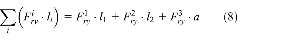
According to D’Alembert’s principle, the mechanical equilibrium equation of the piston system is established as follows


In these equations, φ is the swinging angle of the connecting rod, indicating the angle at the moment from the centerline of the cylinder to the centerline of the connecting rod, with the clockwise direction being positive. ∑Mp indicates the sum of all of the acting torques on the center of the piston pin hole. Fs is defined as

The friction torque of the piston ring-ring groove on the center of the piston pin can be obtained as follows
The inertia force and inertial torque of the dynamics systems in equations (4)–(6) can be expressed as follows


In these equations, mp is the mass of the piston; mpin is the mass of the piston pin; msl is the mass of the small head of the connecting rod;
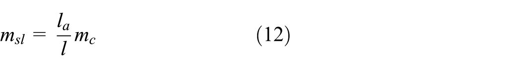
In this equation, la is the distance from the center of the small head of the connecting rod to the barycenter of the connecting rod; mc is the mass of the connecting rod group, which includes the connecting rod, the small head bushing of the connecting rod, the connecting rod cap, and the connecting rod bolt.
According to the principle of the parallel axis of the rotational inertia, the rotational inertia Ic in equation (11) can be obtained as follows

In this equation, Ip is the rotational inertia of the piston on its barycenter; sp is the distance from the piston barycenter to the barycenter of the lateral motion system of the piston; Ipin is the rotational inertia of the piston on its barycenter, and spin is the distance from the piston pin barycenter to the barycenter of the lateral motion system of the piston. Synthesizing the foregoing analysis, the following expression can be obtained
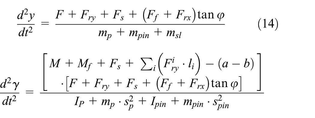
Equation (14) is the secondary kinematics equation of the piston, that is, the mathematical model of the secondary kinematics of the piston. For an internal combustion engine operating at a steady speed, the right side of the equation can be solved by the previously described method. Therefore, the values of
Analysis of the thermal deformations of the piston and cylinder liner
As the piston and cylinder liner temperatures are high and can easily produce thermal deformation, which can change the piston and cylinder shape and spacing, the interaction between piston and cylinder liner can be easily changed. Therefore, the thermal deformations of the piston and cylinder liner should be analyzed to obtain accurate results of piston dynamic performance.
First, the piston surface temperature is tested. Then, the gas temperature and the coefficient of convective heat transfer at the top of the piston are simulated by software. The maximum gas temperature at the top of the piston reaches up to 2500–2600 K in the combustion phase, with the average of 920 K. The equivalent heat transfer coefficient of the gas is 489 W/(m2 K). The pyroconductivity and density of piston material are 142 W/(m K) and 7.9 × 10³ kg/m3, respectively. The elastic modulus and Poisson’s ratio are 2.1 × 10⁵ MPa and 0.3, respectively. The other boundary heat transfer coefficients are determined according to the material properties and shapes.
Table 2 and Figure 6 show the steady boundary conditions and the structure of the piston, respectively. Then, the boundary conditions of the tests and simulations are applied to the finite element models of the piston and cylinder liner. The thermal deformations of the piston and cylinder liner in 360° circumferential directions at the same axial position are considered consistent to simplify the models. Finally, the thermal profiles of the piston skirt and cylinder liner are obtained and shown in Figures 7 and 8, respectively.
Steady boundary conditions of the piston.

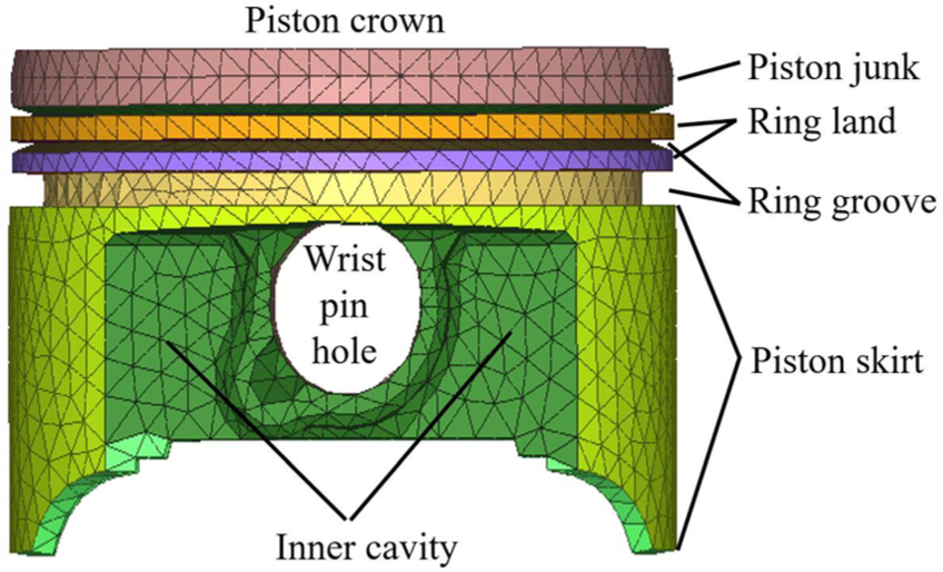
Structure of the piston.

Skirt radial thermal expansion and profile.

Cylinder liner radial thermal expansion and profile.
Analysis of piston dynamics model
Selection of piston dynamic evaluation parameters
The piston dynamic evaluation parameters mainly include displacement and angle of the piston, impact force and friction force between piston and cylinder liner, and energy and power dissipation between piston and cylinder liner. The LF, secondary kinetic energy (SKE), and friction power loss (FPL) are selected to be the piston dynamic evaluation parameters for solving the problem of engine abnormal noise caused by secondary kinetic motion. The direction changes of LF can cause lateral movements of the piston, which make the piston impact the cylinder liner. The SKE of the piston includes three parts, namely, axial, rotational, and lateral directions. The piston impact energy is mainly contributed by the secondary kinetic motions in the lateral and rotational directions. The FPL, which can cause engine vibrations and radiation noise, includes lubricated and boundary frictions.
Optimizing factor determination of the piston structure
In solving the piston dynamic problem and considering the optimization costs and implementation difficulties, five parameters, namely, nominal diameter DCL of cylinder liner, pin offset epin, crankshaft offset ecrank, piston mass Mpiston, and piston rotational inertia Ir, are selected to be the optimizing factors. Thus, the optimization objective function of the piston-crank mechanism is constructed as shown in equation (15)
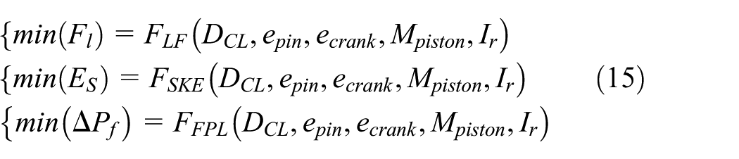
Optimally designing the foregoing structure factors, the LF Fl, SKE ES, and FPL ΔPf all reach the minimum values. According to the actual situation, the constraint condition of the structure factors need to be optimized is given as follows:
Nominal diameter DCL of cylinder liner.
For the piston alloy material, the cold cylinder clearance is generally between 0.0008D CL and 0.0024D CL , so the relation between nominal diameter DCL of cylinder liner and maximum diameter Dskirt of skirt should meet the conditions as equation (16)

2. Pin offset epin
The optimal pin offset can lead to a smooth transition of the piston motion from anti-thrust to main thrust when the LF swerves, thereby reducing the impact energy. The pin offset epin should generally satisfy

3. Crankshaft offset ecrank
The crankshaft offset affects the dynamic performance, the economic performance, and the harshness of the engine, as well affect the impact energy. The ratio of the absolute value of the crankshaft offset ecrank to the crank radius Rcrank is generally in the range of 0.05–0.25, so the ecrank should satisfy

4. Piston mass Mpiston
The piston mass directly affects the reciprocating inertia force and the SKE of the piston-connecting rod system. Reducing the piston mass can reduce the SKE and improve the impact noise. However, to reduce the impact of the gas explosive power on the piston pin and connecting rod, the piston mass cannot be too small. The piston mass Mpiston should satisfy

5. Piston rotational inertia Ir
The piston rotational inertia directly affects the piston LF and the impact energy. To reduce the piston impact noise, the piston rotational inertia Ir should be reduced. In this article, the Ir should satisfy

The orthogonal array method is used to obtain the effect weight information of each factor to the target value and thus improve the efficiency of piston structure optimization. A L64 (43 × 32) orthogonal array is designed, in which the levels of pin offset, crankshaft offset, and liner nominal diameter are four, whereas those of piston mass and inertia are three. The values of the optimization factors are defined on the basis of the original value, as shown in Table 3. The effect of response on the factors is represented by the Pareto chart method. The greater the value, the greater the effect on the response. The linear effects of each factor on the peak and integral of the target value are shown in Figures 9 and 10, respectively. Meanwhile, the main effects of each factor on the peak and integral of the target value are shown in Figures 11 and 12, respectively. By synthetically considering the linear and main effects of the absolute value of the factor on the target value, the crankshaft offset, piston pin offset, and liner nominal diameter are determined to be the key effect factors of the target value. The piston pin offset exerts the greatest effect on the secondary kinetic of the piston. Only one of the LF and FPL should be considered when evaluating the response of optimization factors by reason of the consistent response on both.
Orthogonal array of optimization factor value.


Maximum linear response on target value by factor absolute value: (a) on lateral force, (b) on friction power loss, and (c) on secondary kinetic energy.

Integral linear response on target value by factor absolute value: (a) on lateral force, (b) on friction power loss, and (c) on secondary kinetic energy.

Maximum main effects on target values by factor absolute values: (a) on lateral force, (b) on friction power loss, and (c) on secondary kinetic energy.
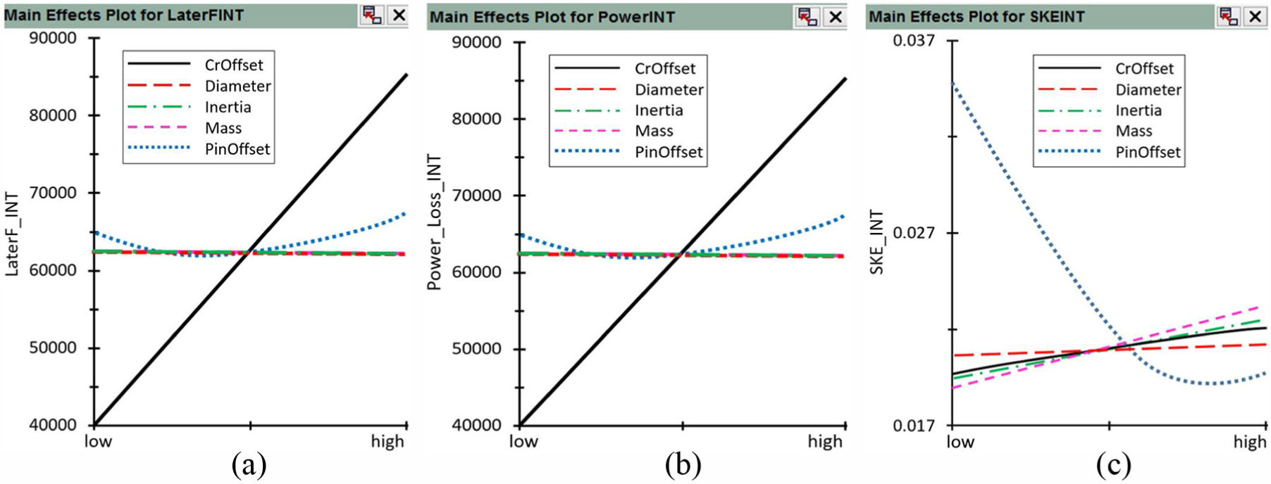
Integral main effects on target values by factor absolute values: (a) on lateral force, (b) on friction power loss, and (c) on secondary kinetic energy.
Analysis of the optimization parameters of the piston structure
In the previous studies of optimization factors, the values of the parameters are close to the original design and are in small ranges. Therefore, the value ranges of crankshaft offset, piston pin offset, and liner nominal diameter, which have been confirmed to be the key factors, should be enlarged and subdivided to confirm additional accurate value ranges. Then, each factor is validated by a full factorial method. The piston mass and inertia present low impact factors that remain the same as the original value, that is, the piston mass is 0.133 kg and the inertia is 5.89 × 10⁻⁵ kg m2, to simplify the calculated amount. Table 4 shows the experimental value obtained using the full factorial method. When one of the factors changes, the two other factors remain unchanged. Each factor changes for 16 times. The structure factors of crankshaft offset, piston pin offset, and liner nominal diameter are analyzed using the orthogonal design method. The results are shown in Figures 13–15.
Table of full factorial.

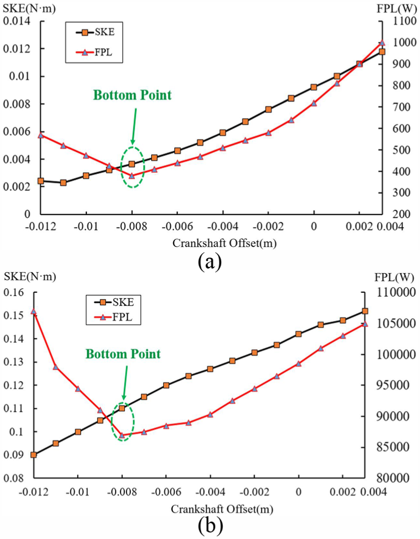
Plots of SKE and FPL of crankshaft offset: (a) maximum of SKE and FPL; (b) integral of SKE and FPL.

Plots of SKE and FPL of nominal diameter of cylinder liner: (a) maximum of SKE and FPL; (b) integral of SKE and FPL.
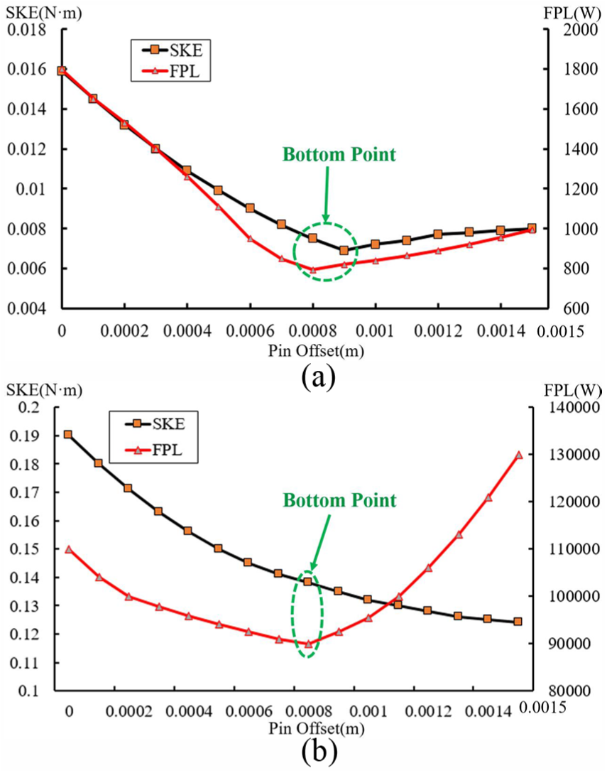
Plots of SKE and FPL of pin offset: (a) maximum of SKE and FPL; (b) integral of SKE and FPL.
In a single factor experiment, assuming that the factor A gets m levels, each of which is repeated n times. Testing a certain level Ai (i = 1, 2,…, m), a group of samples (x1, x2,…, xi) are obtained. Defining
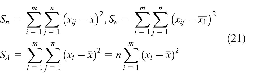
Thereinto,

Equation (22) is named segmentation function of square sum of the deviation. Generalizing to the problem of multifactor, it can be obtained as follows

Additionally, because
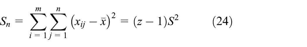
In equation (24), S2 is the sample variance of the data group (x11, x12,…, xmn); z is the data number of the data group. In accordance with the equation group above, the standard error
Standard error of orthogonal experiment.
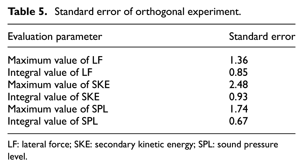
LF: lateral force; SKE: secondary kinetic energy; SPL: sound pressure level.
Figure 13 shows the plots of the FPL and SKE when the crankshaft offset is the design variable. The axes of the main crankshaft journal and the connecting rod journal are not coaxial and are at a certain distance. Thus, when the crankshaft offset is close or equal to the distance, the connecting rod is in a nearly vertical state in the working stroke, in which state the FPL is at a minimum value. When the crankshaft offset is greater or lesser than the distance, the FPL increases equally. In the process of changing the crankshaft offset value from negative to positive, the SKE increases accordingly. By synthetically considering the maximum and integral of FPL and SKE, the friction power is determined to be the smallest and the SKE is relatively small when the crankshaft offset is −0.008 m, which is the best way to improve the vibrations and abnormal noise caused by the secondary kinetic motion.
Figure 14 shows the plots of the FPL and SKE when the nominal diameter of the cylinder liner is the design variable. When the nominal diameter of the cylinder liner is small, the distance between the cylinder liner and the piston skirt is also small; this condition is inconducive to the formation of lubricating oil film. Thus, the FPL is large and increasing the nominal diameter of the cylinder liner is conducive to the formation of good lubrication. However, when the nominal diameter of the cylinder liner increases to a certain extent, the SKE increases rapidly and the LF on the main thrust side increases. Meanwhile, the edge of the piston head dramatically rubs the cylinder liner, thereby destroying the lubricating oil film. Thus, the SPL increases. Obviously, the friction power is the smallest and the SKE is relatively small when the cylinder liner nominal diameter is 0.06552 m, which is the best way to improve the vibrations and abnormal noise caused by the secondary kinetic motion.
Figure 15 shows the plots of the FPL and SKE when the piston pin offset is the design variable. If the piston pin is zero offset, then the piston laterally moves from the anti-thrust side to the thrust side in the case of minimal swing when the piston changes its direction in the working stroke at the TDC. Given that no swing transition process occurs, the piston slaps the inner wall of the cylinder liner, thereby causing the noise. Conversely, the deflecting torque is generated by the pin offset in the working stroke at the TDC, thereby causing the piston to swing before the lateral commutation and reducing the slap of the piston. As the piston pin offset increases, the SKE is nearly straight down and the FPL decreases. However, when the piston pin offset increases to a certain extent (0.0008 m), the swinging angle of advance in the clockwise direction increases. As a result, the bottom of the piston skirt on the anti-thrust side and the top of the piston on the thrust side create great contacts with the corresponding inner walls of the cylinder liner. Thus, the FPL increases and the SKE increases slightly. By synthetically considering the maximum and integral of the FPL and SKE, the friction power is determined to be the smallest and the SKE is relatively small when the piston pin offset is 0.0008 m, which is the best way to improve the vibrations and abnormal noise caused by the secondary kinetic motion.
Determination and analysis of the final optimization parameters of the piston structure
In accordance with the studies above, the final optimization parameters of the piston structure are shown in Table 6. The crankshaft offset, cylinder liner nominal diameter, and piston pin offset all increase compared with original design. However, the offset directions of the crankshaft and pin remain unchanged.
Optimization parameters of the piston construction.

The original and optimized parameters are applied to the piston dynamic model, and the LF, SKE, and FPL are simulated. The results are shown in Figure 16. Figure 16(a) shows that the peak of LF appears at TDC, whereas the LF is relatively small at the other crankshaft angle. The comparison of the optimized and original designs shows that with the absolute values of the crankshaft offset, cylinder diameter, and pin offset increasing at the same time, the swinging angle reverse time is delayed after arriving at the TDC and the LF on the main thrust side is reduced significantly. The absolute value of the maximum peak of the optimized design on the main thrust side is reduced from 1910 to 930 N, with a decline of 51.3%. Meanwhile, the absolute value of the maximum peak of the optimized design on the anti-thrust side is increased from 503 to 812 N. Given the difference values between the maximum peak values of the LF on the main thrust and anti-thrust sides, the LF of the optimized design on the main thrust and anti-thrust sides is balanced. Figure 16(b) shows that the maximum peak value of the FPL appears on the main thrust side in the working stroke. The comparison of the optimized and original designs indicates that with the concurrent increase in the absolute values of the crankshaft offset, cylinder liner diameter, and pin offset, the peak value of the SPL decreases from 825 to 493 W, with a decline of 40.2%, and the peak time is delayed. Figure 16(c) shows that all of the peaks of optimized design are lower than those of the original design. The comparison of the optimized and original designs indicates that the maximum peak value is reduced from 3.55 × 10⁻³ to 2.42 × 10⁻³ N m, with a decline of 31.8%, with the concurrent increase in the absolute values of the crankshaft offset, cylinder liner diameter, and pin offset. The optimized design presents the lowest peak power in LF, friction power, and SKE compared with the original design, which proves that the optimized design exerts an obvious improvement effect on the noise problem caused by piston secondary motion.

Plot of simulation results of piston dynamic: (a) lateral force, (b) friction power loss, and (c) secondary kinetic energy.
Experimental verification of the optimization design
In accordance with the optimization design method, the piston sample is manufactured to replace the original cylinder engine for bench acoustics test. The noise spectrum characteristic of the optimized design of the single-cylinder gasoline engine under idling condition is obtained and compared with the original design test result, as shown in Figure 17.

Noise spectrum characteristics of original and optimization: (a) measuring point L and (b) measuring point R.
Figure 17 shows that compared with the original design of the piston structure, the amplitudes of the SPL corresponding to the abnormal frequency bands L1, R1, and R2 are significantly reduced. Meanwhile, the SPL amplitudes of the other frequency bands L2, R3, and R4 are significantly reduced. The root mean square value of the SPL of the first 10 s is obtained by integrating the noise spectrum. The results show that the SPL at measuring point A reduces from 80.6 to 77.5 dB(A), with a decline of 3.1 dB(A). Meanwhile, the amplitude of the SPL at measuring point A reduces from 79.5 to 77 dB(A), with a decline of 2.5 dB(A). In addition, the abnormal noise of the original engine under idling condition is eliminated and the sound qualities of the other working conditions do not deteriorate.
Conclusion
In this study, the identification of the noise source and the control method of idling abnormal noise of a single-cylinder gasoline engine are investigated. Through the analyses of the noise spectrum and sound intensity, the abnormal noise source is identified as the medium frequency impact noise caused by the abnormal dynamic performance of the piston mechanism in idling condition. The orthogonal array method is used to analyze the piston structure parameters and to select the factors that exert a significant influence on the piston dynamic performance to solve the abnormal noise problem, reduce the piston’s LF, SKE, and FPL, and obtain the optimized designed. The following significant conclusions are obtained:
The LF, SKE, and FPL are the most important indices that can be used to evaluate the piston dynamic performance. The piston impact noise is closely related to the crankshaft offset, cylinder liner nominal diameter, and piston pin offset for a single-cylinder gasoline engine in idling condition. Through the optimization of the design of piston structures on the basis of the multibody model, the piston dynamic performance can be improved by the orthogonal array method. After implementing the optimization design method, the LF, SKE, and FPL of the piston are reduced by 51.3%, 40.2%, and 31.8%, respectively. Thus, the dynamic performance of the piston mechanism can be improved.
The acoustic verification tests are implemented on the basis of the original engine when the optimized sample is manufactured and installed in the engine. The results show that the abnormal noise is eliminated and the overall SPL of the engine is reduced by 2.5 dB(A) in idling condition. Meanwhile, the subjective evaluation results show that the sound quality is obviously improved. The dynamic performance of the piston can be improved by optimizing the piston structure to reduce the impact noise. Moreover, the sound quality of the single-cylinder gasoline engine can be improved.
The dynamic performance of the piston is improved and the sound quality of the engine is promoted by revising the parameters of the crankshaft offset, cylinder liner nominal diameter, and piston pin offset. The method proposed in this study comprehensively considers the difficulty of actual implementation and the improvement effect and is a relatively simple and feasible method. However, this study does not explore the most effective method from a variety of methods. This subject will be implemented and improved in future research.
Footnotes
Handling Editor: Chuanzeng Zhang
Declaration of conflicting interests
The author(s) declared no potential conflicts of interest with respect to the research, authorship, and/or publication of this article.
Funding
The author(s) disclosed receipt of the following financial support for the research, authorship, and/or publication of this article: This work was supported by the National Key Research and Development Plan (grant number 2016YFD0700704) and the Fundamental Research Funds for the Central Universities (grant numbers WUT: 2014-VII-004 and WUT: 2016IVA037).