
Abstract
A walking companion robot is presented for rehabilitation from dyskinesia of lower limbs in this article. A new human–robot interface (HRI) is designed which adopts one-axis force sensor and potentiometer connector to detect the motion of the user. To accompany in displacement and angle between the user and the robot precisely in real time, the common motions are classified into two elemental motion states. With distinction method of motion states, a classification scheme of motion control is adopted. The mathematical model-based control method is first introduced and the corresponding control systems are built. Due to the unavoidable deviation of the mathematical model-based control method, a force control method is proposed and the corresponding control systems are built. The corresponding simulations demonstrate that the efficiency of the two proposed control methods. The experimental data and paths of robot verify the two control methods and indicate that the force control method can better satisfy the user’s requirements.
Keywords
Introduction
Many countries have stepped into aging societies with many ambulation dysfunction people. Meanwhile, they have to face the shortage of nursing care. 1 There are growing requirements in developing mechanism equipment to replace nursing in helping those people to walk. Robotics is regarded as a promising technology to solve this problem. 2,3
Scholars and researchers have made some contributions to developing intelligent walker robot recent years. The main difficulties in developing a walker robot lie in the following three aspects: (1) robot mechanism design; (2) human–robot interface; and (3) control system based on the human–robot interface.
The walker robot mechanism should possess both stability and flexibility to support the partial body weight of its user and accompany the movement of the user timely. With respect to stability, researchers usually enlarge the base of the walker robot or balance placement of heavy elements (e.g. motors, batteries, electronics, etc.) at lower planes of the robot. 3 As for flexibility, one typical type of mobile base consists of three Mecanum wheels 120° apart from each other. 4,5 Another typical type of mobile base utilizes a pair of casters as front wheels and two rear wheels driven by two DC motors. 6
Human–robot interface is of crucial importance for a walker robot because it directly influences the control algorithms and control effect. When designing the human–robot interface, researchers need to take into account not only the functionality but also the user-friendliness because of the user’s deficiencies at cognitive and sensory levels. 3 The design of human–robot interface involves two difficulties: the selected variables of body should fully reflect the motion state of the user and the sensors adopt to effectively measure the selected variables. Many researchers select upper body strength to reflect the user walking motion. To get abundant information for the user movement, many researchers use a six-axis force/torque sensor or tridimensional (3-D) force sensors to detect the force the user poses on the robot. 4,7 –12 In order to lower the cost of the walker robot, many researchers utilize relatively low-cost sensors to replace the six-axis force/torque sensor. Tang and Cao used force-sensing resistors to detect the pull or push pressure that the user poses on the handlebar of the robot. 13 Ye et al. proposed a special arrangement of one-dimensional push–pull force sensors to measure the interactive force and torque between the human and the robot. 14 Jiang and Wang used four force sensors embedded in the armrest. 15 Patel et al. used two strain gauges on each of the walkers handlebars to detect indicative pressure. 16 Huang et al. developed a pair of force grip handles using 13 force sensors for the left/right hand. 17 Martins et al. designed a new handlebar composing of two linear potentiometers and one rotary potentiometer to read the user’s walking intentions qualitatively. 18 Some researchers select lower limbs to reflect the user motion. JAIST (Japan Advanced Institute of Science and Technology) robotic walker employed a pair of rotating infrared sensors to detect the location of the user’s lower limbs and locate the user’s lower limbs in real time. 5,19 Some researchers use vision-based methods to detect the user state. Taghvaei et al. used a depth sensor to estimate the human state. 20,21
Based on the types of human–robot interface, the control algorithms are used accordingly. Many available control algorithms have been employed in walker robot control systems. Admittance control algorithm and variant of admittance-based control algorithm are widely used in the walker robot. 4,7,8,10,11,13 Fuzzy control is also widely used. 12,15,18,22 Other control algorithms such as learning algorithm, 23 smooth control, 24 and Bayesian Networks mode 16 are also adopted to the walker robot.
Although more and more functions (e.g.: fall prevention, 25,26 obstacle avoidance, 27 health monitoring, 8 and outdoor guidance 28 ) are attached to the walker robot, many walker robot are not designed according to a clear requirement from the target group. To archive a goal of real-time precise accompany in displacement and angle between the user and the robot, further researches are still required. The precise motion control highly depends on the design of HRI. Researchers have developed various kinds of HRI for walker robots and verified their effectiveness, however, there is still some space for improvement. First, the six-axis force/torque sensors or 3-D force sensors are required to remove noise (Kalman filters 19 and G-h filters 12 ), and the responding time would be extended, which has a great impact on the user comfort. Second, it is difficult to build a mathematical model between the sensors outputs and the user’s postures or gestures during gait, 12,18 therefore, it is not easy for motion control. Third, the costs of six-axis force/torque sensors or 3-D force sensors contribute little to the extension of walker robots. Finally, the upper body strength may not be the most suitable variable to detect for reflecting the motion of the user. Because many patients display upper-limb discoordination symptoms after stroke. 29 The lower limbs can reflect the user motion effectively, but the sensors on the lower limbs would put burden on the user, especially for the dyskinesia of lower limbs.
The main purpose of this article is to present our walking companion robot and its motion control algorithms. This article is organized as follows. The section “Walking companion robot design” describes the integrated design and kinematics of walking companion robot. In the section “Motion control for different motion states,” we analyze how the human–robot interface distinguishes the different motion states and propose two motion control methods. In the section “Stability analysis of motion control,” we analyze the stability of control systems. The simulation results of the two motion control methods are provided in the section “Simulation results and analysis.” The section “Experiments” presents experimental results. Finally, the conclusions and future work are given in the section “Conclusion and future work.”
Walking companion robot design
A survey of target group requirements for a satisfactory walker robot was made in China rehabilitation research center (CRRC). Based on the results of the survey, their requirements are summarized as follows: (1) a kind of flexible mechanical structure that can give user a sense of security; (2) as few operation rules as possible, especially operation rules for upper limbs; and (3) light weight and low cost. In addition, other researchers’ conclusion of walker robot should be taken into consideration. To make the user feel relaxed during walking, the input forces to drive the robot should be small in all conditions. For the user, the required operation force should be small, better no more than 20 N. 30 Based on the above analysis, we design a walking companion robot.
Mechanical structure of walking companion robot
Mechanical structure design
In order to use more security, we design four enclosed layers mechanical structure for different functions (namely top layer, middle layer, lower layer, and bottom layer). The sketch and photo of the robot are shown in Figure 1. The user enters the robot via four doors in the back of four layers. To give user support and protection, the top layer is designed. The motion of waist is selected to detect the motion of the user, and thus the middle layer is designed with human–robot interface fixed in this layer. To meet different height requirements of the users, the heights of the top and middle layers are adjustable. The bottom layer is the mobile chassis. Considering the movement characteristics of the users, the bottom layer should have a translation freedom in Y-axis and a rotation freedom in Z-axis. Therefore, two-wheeled differential-driven structure is adopted in the bottom layer.

Walking companion robot prototype.
Stability analysis of mechanical structure
The robot should be stable when the user falls down. A threshold value Vmax is set for the robot velocity (V). When V ≥ Vmax, the robot should slow down and serve as a stable handler for the user. The break should not be too sudden to hit the user nor too slow to have a long breaking distance. The force analysis in this case is shown in Figure 2.

Stability analysis when user falls down.
There are four categories of force considered: the gravity of the user (

The tension is

Since there is a breaking distance when the robot slows down,

The force in the direction along with the user body is countervailed by the supporting force (

As we assume the feet of the user would not slip, we can know that the supporting force and friction force are made even by the counter force from the ground.
The force in Y direction can be calculated as following

The breaking distance can be set to RB


Torque of robot

Torque of user

Torque of collision force


The stability of the robot should satisfy the following conditions

that is

The values of
After consulting the experienced doctors and nurses in rehabilitation center, we estimate the values of parameter
Referring to the medical literatures,
31
–33
we set the user physical parameters


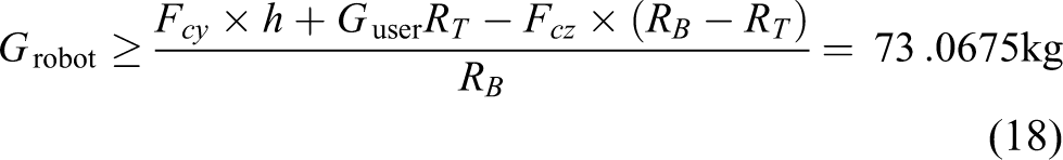
Finally, we have the robot weight at a minimum of 73.0675 kg.
The robot weight is about 75.5 kg (including the battery pack, motors, and other electronic components), and thus the robot can be stable when the user falls down.
Human–robot interface design
Human–robot interface plays a critical part because it is the basic of the motion control of a robot. Walking companion robot human–robot interface consists of the force–sensor interface and the potentiometer connector.
The target group includes many hemiplegic patients who display upper-limb discoordination symptoms after stroke. 29 Therefore, the waist strength responses the motion intent of them more efficient than the upper body strength does. The force sensor interface employs two one-axis force sensors. Detecting upper body strength requires the user to put his hand in specific armrest during the whole walking process, which is dissatisfactory according to the above survey. To detect the interactive force between the user and the robot, a new arrangement of two one-axis force sensors is proposed. The installation position of two one-axis force sensors is shown in Figure 3. One end of elastic string is tied to the waist of the user and the other end of the string is connected a one-axis force sensor. When the user begins to move, the output of one-axis force sensor will reflect the motion intent of user.

Installation position of two force sensors.
To cover the shortage of one-axis force sensor, a novel potentiometer connector installed between the force sensor and the middle layer is designed. The mechanical structure is shown in Figure 4. The one-axis force sensor is connected to the rotation axis by screw threads. The self-reset potentiometer is steadily connected with supporting pedestal. When the user is turning, the one-axis force sensor and potentiometer will rotate in Z-axis. The output of one-axis force is the actual one-axis force on the string. The output of potentiometer can reflect the direction of rotation.
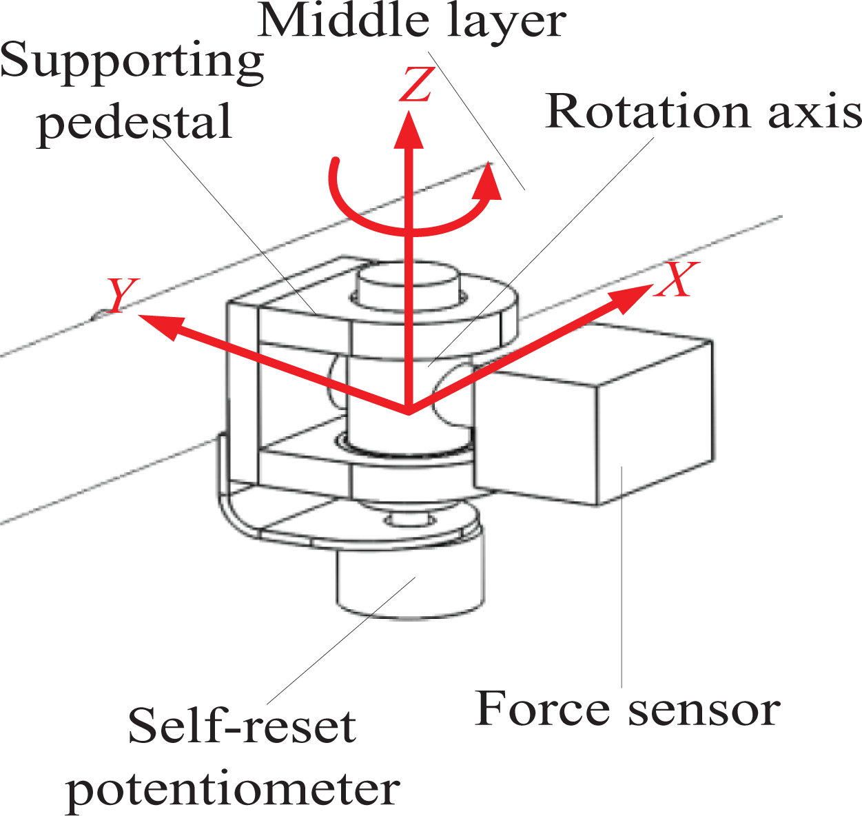
Potentiometer connector structure.
Electronics implementation
The hardware schematic is shown in Figure 5.

Electronics implementation.
Kinematics of walking companion robot
Due to the limitation of motor driver, we can get output values of absolute turns of motors (
The absolute positions of two wheels pos L and pos R are

where kr is the reduction ratio.
Figure 6 shows the trajectory of robot in one sampling period. The actual paths for robot center of mass (COG) and two driven wheels are arcs. Because the sampling period is too short, the arcs can be seen as straight lines. We use

Transition algorithm in motion state I.


The relative angle of robot is

The coordinate of robot COG in the k + 1(th) sampling period is
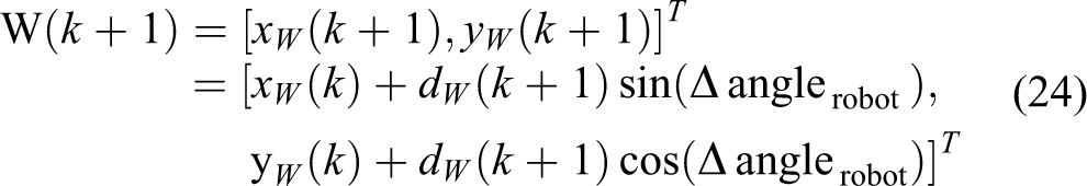
Figure 7 shows transition algorithm in motion state II


Transition algorithm in motion state II.
Suppose

then we can get


The coordinate of robot COG in the k + 1(th) sampling period is

Motion control for different motion states
Recognition of elemental motion state
The doctors and nurses in CRRC demanded that the robot can help patients to walk slowly on flat path and suggested two common elemental motion states of human (as shown in Figure 8). Motion state I occurs when user is going straight. Motion state II occurs when user is rotating in one spot (clockwise rotation or counterclockwise rotation). The reference frame O-XY is built to introduce a concept: relative motion variables. A set of relative motion variables in a sampling period (denoted by

Coordination definition of the robot system.
The human–robot interface would generate corresponding output when user begins to move. So the motion state can be indicated by the interaction force between the user and the robot. The outputs of two one-axis force sensors in initial state (the moment when user begin to walk with the help of robot) are
Rule set (rule-based method)
If
If
If
Mathematical model-based control method
The first proposed motion control method was the mathematical model-based control (MMBC). Here, we introduced a concept: calculated motion variable. Calculated motion variables (consists of
Motion state I
We first built the mathematical model in motion state I. Figure 9 shows the interactive force analysis in motion state I.

Interactive force analysis in motion state.
The mathematical model between force sensor data and calculated motion variable is shown in equation (36)

where

ω(t) is a combination of sensor noises and user individual difference;

MMBC block diagram. MMBC: mathematical model based control.
Because there is possibility that

The user always moves faster than the robot and the motion control system should response as soon as possible, so the classic and simple Proportion Integration Differentiation (PID) controller is adopted. The desired angular displacements of the right and left driving wheels are

The torque of the right and left driving wheels is

The actual angular displacements

where
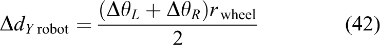
The robot actual displacement is
Motion state II
Clockwise rotation at one spot was taken as example in the following analysis of motion state II. The interactive force analysis in motion state II is shown in Figure 11.

Interactive force analysis in motion state II.
The mathematical model in motion state II is shown in equation (43). Because the two sensors have a rotation freedom in Z-axis, the outputs of them are the actual one-axis force on the string

In the equation,

where

a is estimated based on Chinese elder average waistline.
The control system in motion state II is similar to which in motion state I except the inverse kinematic and kinematic module. The desired angular displacements of the right and left driving wheels are

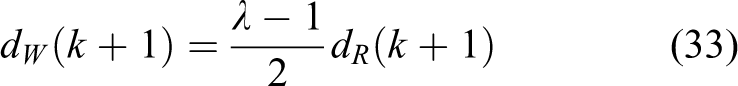
The robot actual angle is

Defect analysis of MMBC system
In MMBC system, there are two main deviations as follows. 1. Calculation for force value F
In calculation of calculated motion variable, force value F(N) must be handled first. Force value F is calculated from sampled Analog/Digital converter (A/D) voltage data, that is,
2. Parameters determination in mathematical model
The parameters
Finally, for the existence of the unavoidable deviation, the calculated motion variable (Δdy or γ) would be in deviation. Furthermore, the two deviations are difficult to be eliminated by improving the controllers. So another control system needs to be developed to avoid the deviation.
In the experiment of force control (FC) system, we plan to use sampled AD voltage data (mV) instead of the calculated force value in order to avoid inaccurate force value calculation due to the sensor. So FC method may be more likely to achieve the accurate control than MMBCS.
Above analyses of two control strategies are just rough analyses and theoretical inference, experimental verifications are required to determine the pros and cons.
FC method
To overcome the disadvantages of MMBC method, a FC system is proposed, which do not rely on mathematical model and avoided too much imprecise calculation. The force sensor data serve as the feedback of the control system rather than the input of control system. The FC basic concept is: when the real-time force sensor data equals to the initial state force sensor data, it indicates that robot moves at the same pace or rotate at the same angle with user. The robot is seen as a stable system and the motion of user is seen as the disturbance, the initial output of the force sensor is seen as the reference input. The control objective is to make the real-time output of force sensors equal to the initial one-axis force sensor data by adjust the motion of robot.
Motion state I
The control block diagram of FC method is shown in Figure 12. In motion state I, the reference input of the system is the back force sensor data in initial state F0YB. Based on the FC basic concept, the deviation signal of FC system is

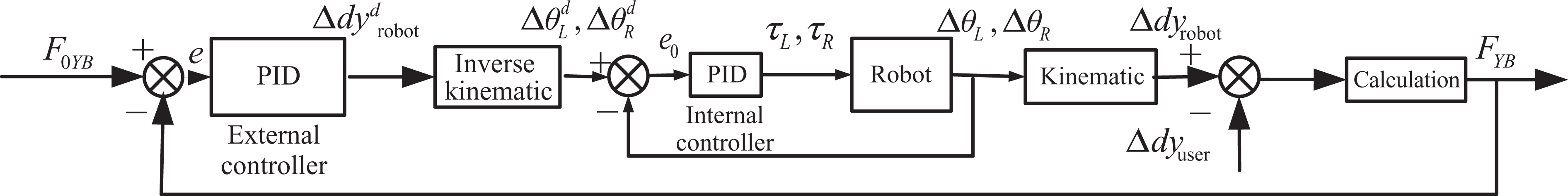
FC method in motion state I. FC: force control.
When the user begins to move, e < 0.
The desired displacement of robot can be get through PID external controller
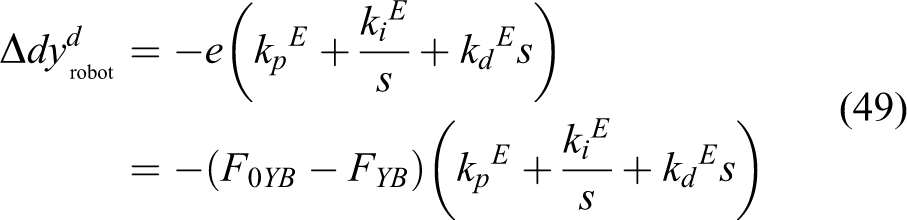
The desired angular displacements of the right and left driving wheels are

The actual angular displacements

Motion state II
Clockwise rotation at one spot is also taken as example for FC system. There is only a small difference between states II and I.
The desired angle of robot can be got through PID external controller

The desired angular displacements of the right and left driving wheels are

The robot actual angle is

The real-time back one-axis force sensor data FYB is the feedback of control system and can be calculated as

Stability analysis of motion control
The stability is also important for a control system. The stability of two control methods is analyzed as following.
Stability analysis of MMBC method
The math model module in MMBC method does not influence the stability of the system, so it is not taken into consideration in the analysis of system stability.
Stability analysis of MMBC system (motion state I)
The close-loop transfer function of the system is

where m is the mass of the robot.
The characteristic equation of the system is

The roots of characteristic equation are

The sufficient and necessary condition of regional stable for the system is s1,2 < 0 or s1,2 possess a negative real part.
The controller parameters should satisfy the following equations (58) or (59)


Stability analysis of MMBC system (motion state II)
The close-loop transfer function of the system is
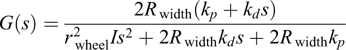
where I is the moment of inertia of the robot.
The characteristic equation of the system is

The roots of characteristic equation are

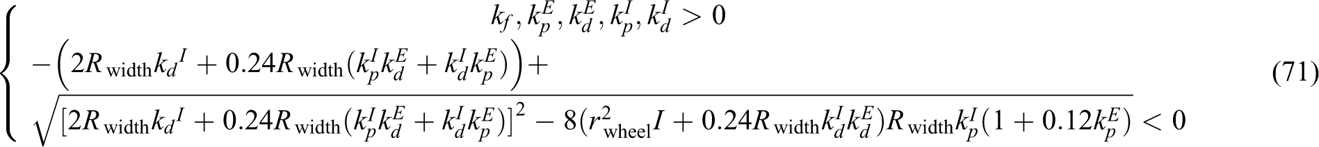
The sufficient and necessary condition of regional stable for the system is s1,2 < 0 or s1,2 possess a negative real part.
The controller parameters should satisfy equation (62) or (63)


Stability analysis of FC method
Stability analysis of FC system (motion state I)
The open-loop transfer function for the closed-loop control system is

The characteristic polynomial is

The poles of the system are

The sufficient and necessary condition of regional stable for the system is s1,2 < 0 or s1,2 possess a negative real part.
The controller parameters should satisfy the following equation (66) or (67).


Stability analysis of FC system (motion state II)
The open-loop transfer function for the closed-loop control system is

The characteristic polynomial is

The poles of the system are

The sufficient and necessary condition of regional stable for the system is s1,2 < 0 or s1,2 possess a negative real part

Simulation results and analysis
MMBC system
Simulink (include in MATLAB R2009a) is utilized to conduct the simulations in order to verify the efficiency of the two control algorithms. The simulation results of MMBC system (motion states I and II) are shown in Figures 13 and 14. The user relative motion variables (

Simulation result of MMBC system (motion state I). MMBC: mathematical model-based control.

Simulation result of the MMBC system (motion state II). MMBC: mathematical model-based control.
The controller parameters (motion state I) in simulation are
The controller parameters (motion state II) in simulation are
FC system
The simulation results of the FC system (motion states I and II) are shown in Figures 15 and 16. We also use a signal with acceleration and deceleration to simulate the user’s relative motion. In Figures 15(a) and 16(a), the fitting degree between two lines shows that the signal variables of the robot relative motion (

A simulation result of FC system (motion state I). FC: force control.
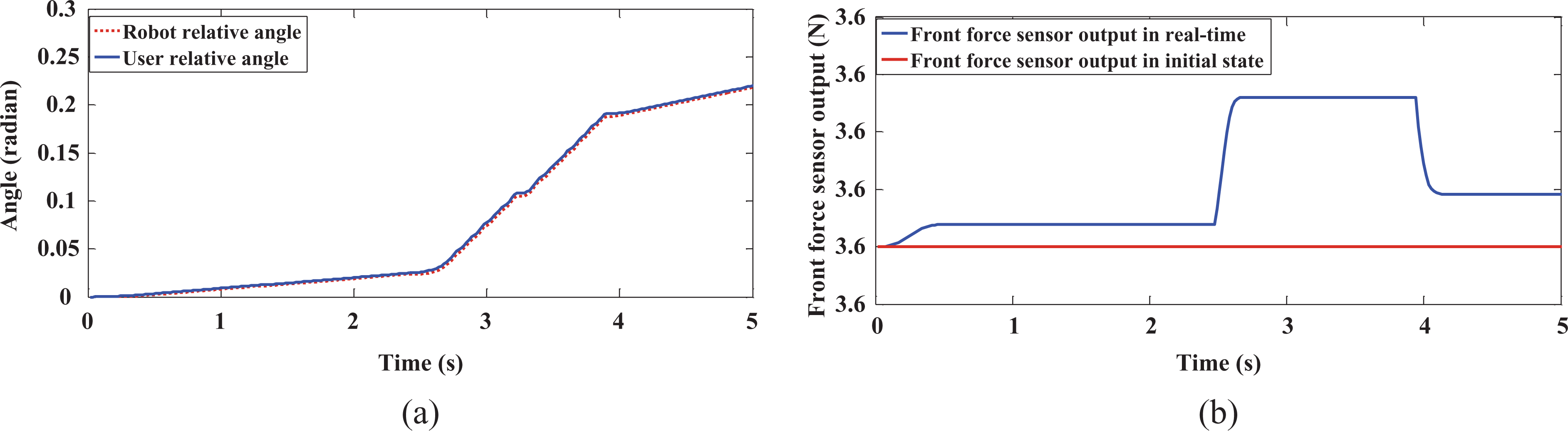
Simulation results of FC system (motion state II). FC: force control.
The controller parameters (motion state I) in simulation are
The controller parameters (motion state II) in simulation are
Experiments
Before the overall experiment, the proportionality coefficient kliner from sampled AD data (mV) to force value (kg) is measured about 700–750. kliner varies between each power on and cannot be measured precisely as expected.
To verify the control algorithms, a participant is asked to go straight (motion state I) and rotate in one spot (motion state II), while the samplings of the relevant data are taken. The experiment photos are shown in Figure 17.

Photos of field experiment.
The first problem for the overall experiment is how to acquire the ground truth path. For mobile robot location, many scholars acquire robot ground truth path by motion capture system (VICON motion system 35 and top-down camera tracking system (UGV) 36 ), global positioning system (GPS 37 and the combination of radio frequency identification (RFIR) and encoder, 38 but that is actually unnecessary for a walker robot. For the walker robot location, most researchers calculate the ground truth paths by motor turns. 4,8,28 Researchers use simple concepts like best-fit line 4 and desired path 8 to represent the user ground truth path. We use best-fit line to represent the user path in this article. The comparison method and best-fit line concept are introduced as follows:
To quantitatively evaluate the coincidence between the motion of robot and the user’s walking intention, we assume a metric that is given by

where N is the data number of a motion path of the robot;
Motion state I
In the experiment of motion state I, a patient was asked to go straight along the reference path with the help of walking companion robot. The distance from the starting point to the finishing point is 4.6 m. As shown in Figure 18, the differences between the two paths and the reference path are small and can meet the needs of user. The path of MMBC method has an error in terminal point in Y-axis (which is about 0.05 m). The path of FC method also has an error in terminal point in Y-axis (which is about 0.008 m) that verifies the deviation analysis of MMBC method. This fact was further proven by calculating the average values of DIF(robot,user) see Table 1). The angles of robot with two control methods are shown in Figure 19. The errors in angle of the robot with two control methods are also small. Both the errors in displacement (X-axis) and angle increase with time. Those errors are time-accumulated errors, which are too small to effect use’s comfort. In Figure 20, the big difference between front force sensor output and back force sensor output indicated the user is in motion state I. The back force sensor output in MMBC system was no more than 16 N (as shown in Figure 20(b)), while in FC system was no more than 12 N (as shown in Figure 20(a)). These met with the requirements from the previous survey.

Paths comparison for two control methods (motion state I).
Comparison of DIF(robot,user) using different control methods.

MMBC: mathematical model based control; FC: force control.

Angle of robot with two control methods (motion state I).

Force sensor outputs of two control systems (motion state I).
The controller parameters (MMBC method) in field experiment are
The controller parameters (FC method) in field experiment are
Motion state II
In the experiment of motion state II, a patient was asked to rotate in one spot. Figure 21 shows the paths with two control methods in motion state II. The error in displacement is acceptable for user. Obviously, the error of path with FC method was small than the error of path with MMBC method. This fact was further proven by calculating the average values of DIF (robot and user; see Table 1). Data in Figure 22 shows the angle of robot. The angle of MMBC method has an error in terminal point (which is about 5°). The angle of FC method has an error in terminal point (which is about 2°). Figure 23 shows the small difference between front and back force sensor, which can indicate the user is in motion state II. The back force sensor output in MMBC system is no more than 12 N (as shown in Figure 23(a)), while output in FC system is no more than 11 N (as shown in Figure 23(b)). These made user comfortable from the previous survey.

Paths comparison for two control method (motion state II).

Angle of robot with two control methods (motion state II).

Force sensor outputs of two control systems (motion state II).
The controller parameters (MMBC method) in field experiment are
The controller parameters in field experiment are
Feedbacks from the participants
Twenty patients in CRRC were asked to use the walking companion robot. According to the feedbacks from these participants, we summarized the following conclusions as shown in Table 2.
Feedbacks from 20 participants.

MMBC: mathematical model-based control; FC: force control.
These feedbacks verify the previous theoretical analysis of the two control strategies.
Conclusion and future work
This article proposed a new walking companion robot, which is different from the existing walker robot in mechanical structure and human–robot interface. Two motion control methods of this robot were studied based on online estimating user motion state.
The main contribution of this study is to design a novel human–robot interface which has the advantages of low noise and low cost. Based on the human–robot interface, an online inference algorithm for user motion state and two motion control methods was proposed. The inference algorithm and the two motion control methods were simple so that the robot can respond quickly when the user moves. The simulation and experiments verified the effectiveness of the proposed algorithms. The comparison of the two control methods was made using other researchers’ methods. The comparison indicated that the FC method can better satisfy the user than the MMBC method.
Still, this robot could be better if we can fulfill the following requirements in future work:
First, the two elemental motion states were not plenty for human motion, whereas they are just our first steps. We can further add more elemental motion states for control.
Second, the detection and prevention against falling down should be added in the robot. Falling down could be lethal for the users and thus it is essential to add this function.
Footnotes
Declaration of conflicting interests
The author(s) declared no potential conflicts of interest with respect to the research, authorship, and/or publication of this article.
Funding
The author(s) received no financial support for the research, authorship, and/or publication of this article.