
Abstract
This article presents an online three-axis non-uniform rational B-splines preprocessing and feedrate scheduling method with chord error, axial velocity, acceleration, and jerk limitations. A preprocessing method is proposed to accurately locate the critical points by reducing pre-interpolation feedrate in feedrate limit violation regions. In the preprocessing stage, the non-uniform rational B-splines curve is subdivided into segments by the critical points and the corresponding feedrate constraints are obtained. A sliding look-ahead window-based feedrate scheduling method is proposed to generate smooth feedrate profile for the buffered non-uniform rational B-splines segments. The feedrate profile corresponding to each non-uniform rational B-splines block is constructed according to the block length and the given limits of acceleration and jerk. The feedrate modification method for non-schedulable short blocks is also described which aimed at avoiding feedrate discontinuity at the junction of two non-uniform rational B-splines blocks. With the proposed method, a successful feedrate profile could be generated with sufficient look-ahead trajectory length in the buffer, which enables that the preprocessing and feedrate planning to be performed progressively online. Simulation and experimental tests with different non-uniform rational B-splines curves are carried out to validate the feasibility and advantages of the proposed method. The results show that the proposed method is capable of making a balance between the machining efficiency, machining precision, and computational complexity.
Keywords
Introduction
Conventional computer aided design (CAD)/computer aided manufacturing (CAM) systems usually fit a curved cutter paths proximately with a set of small linear/circular (G01, G02) blocks. During high speed computerized numerical control (CNC) machining, the discontinuities and abrupt direction changes of feedrate among blocks cause overshoots and rapid vibrations in the machine mechanics, degrading surface quality and machining accuracy. Modern CAD/CAM systems are able to express complex curves with parametric functions such as non-uniform rational B-splines (NURBS). 1 The parametric interpolator generates fine position commands from the NURBS curve directly without segmentation contour processing. Although there is no approximation error between the NURBS curve and the desired tool path, the processing speed must be reduced to ensure high-tracking accuracy in large curvature regions. In recent years, great efforts have been made on look-ahead feedrate planning.
For parametric curves, various features have been covered in studies on feedrate planning, including confined chord error/contour error,2–4 acceleration/jerk limitations, 5 servo dynamics constraints,6–9 and constant material removal rate. 10 In these works, the basic idea is to obtain the fastest allowable feedrate in feedrate-sensitive regions taking into account different constraints. With compromising to the speed in these areas, a feedrate profile is generated based on S-shaped acceleration/deceleration control. The most important step in this process is to determine the locations of feedrate crucial points and calculate corresponding tolerant velocity. The most common approach to find the feedrate-sensitive regions and critical points is to pre-interpolate the NURBS curve with a constant feedrate or a constant position increment. For example, Erkorkmaz and Altintas 11 introduced a jerk-limited feedrate profile generation algorithm for quintic spline. A reference trajectory is generated with a constant position increment before feedrate profile generation. ZY Jia et al. 3 presented an NURBS interpolator with constant speed at feedrate-sensitive regions under drive and contour-error constraints. The feedrate-sensitive regions are found in an off-line preprocessing stage with constant feedrate adopted.
There is a trade-off between positioning accuracy and processing speed when determining the constant feedrate in finding the critical points. If a faster speed is adopted in the pre-interpolation step, which means longer displacement along the curve at each step, the referenced high curvature points are likely to be farther from the actual local maximum curvature points. On the other hand, slower feedrate generates more accurate location of critical points, but large amount of calculation is induced in the meanwhile, making it inappropriate to real-time application. This article presents a local fine pre-interpolation method which balances critical point positioning accuracy and processing speed. During the iterative pre-interpolation process, the feedrate is reduced to a lower value at feedrate-sensitive regions to generate reference points more densely, such that the critical point is approximated more accurately. The proposed local fine preprocessing method can significantly improve the critical point positioning accuracy without a large increasing the computation time.
In most prior works, a predefined kinematic profile is used to generate smooth feedrate profiles. In Erkorkmaz and Altintas, 11 the formulation and implementation of jerk-limited S-shaped polynomial feedrate profile are described in great detail. This form of S-shaped acceleration (ACC)/deceleration (DEC) profile is widely used in many researches.12–14 The S-shaped polynomial feedrate profiles have complex expressions and involve many parameters. Lee et al. 15 constructed a velocity profile using trigonometric sine function. The sine-curve velocity profile has a more concise expression of formula than S-shaped velocity profile. Y Wang et al. 16 proposed a sine function–based feedrate scheduling method so as to generate jerk continuous feedrate profile. The non-schedulable situation one may encounter when scheduling feedrate for a short NURBS block is not discussed detailedly in Lee et al. 15 and Wang et al. 16 In this article, a jerk-limited feedrate function is constructed using cosine function. According to the length of an NURBS block, four types of situations are analyzed so as to generate appropriate form of feedrate profile, including the non-schedulable situation.
In order to eliminate the feedrate violation between the non-schedulable block and its adjacent blocks, a look-ahead module is needed to check feedrate limits along the curve. Zhong et al. 17 proposed a look-ahead method with dynamic look-ahead length. The look-ahead length is calculated as the time required for a full stop. However, the influence of non-schedulable block to the adjacent blocks is not considered. The feedrate correction of non-schedulable blocks will cause reschedule of their adjacent blocks. Erkorkmaz et al. 18 proposed a windowing-based feedrate optimization algorithm. But the connection profile between two adjacent look-ahead windows needs to be rescheduled. In this article, a sliding window-based look-ahead method is proposed to identify the non-schedulable blocks ahead of schedule. The windowed look-ahead method is performed progressively on fixed length of trajectory, so there is no need to preprocess the NURBS curve completely before feedrate scheduling. Consequently, the preprocessing and feedrate profile generation could run simultaneously in online space, which is beneficial for machining long tool paths. By comparison, the feedrate scheduling is accomplished in the off-line stage in some prior works.3,15
Since the feedrate profile generation is displacement-controlled, and the NURBS interpolation uses chord length to approximate the curve length by its very nature, the terminal error always exists at the end of an NURBS block when interpolating the NURBS curve with the scheduled feedrate profile. In this article, a compensation feedrate profile scheduling method is proposed to eliminate the terminal error, which also considers the rounding error at the transition point between a constant speed stage and a variable speed stage.
The innovative contribution of this article is summarized as a systematic NURBS interpolator with online NURBS preprocessor and look-ahead feedrate generator, which is favorable to long NURBS tool paths machining. The significances and advantages of the proposed NURBS interpolator are as follows: (1) the proposed local fine preprocessing method can significantly improve the critical point positioning accuracy without a large increasing the computation time; (2) the proposed sliding window-based look-ahead feedrate scheduling method could generate successful feedrate profile with limited length of reference trajectory, and hence, there is no need to preprocess the NURBS curve completely before feedrate scheduling; and (3) the interpolation terminal error is compensated while keeping the smoothness of the feedrate profile, and the feedrate fluctuation is decreased significantly by employing parameter compensation method, which is conductive to guaranteeing the machining precision and protecting machine tools from unwanted vibration.
The rest of this article is organized as follows. The “Development of the interpolation scheme” section presents some background knowledge of NURBS interpolation, and the architecture of the proposed NURBS interpolator is also described. The “Feedrate scheduling algorithm” section describes the proposed NURBS preprocessing and feedrate scheduling methods. The “Simulation and experimental results” section presents the simulation and experimental results. Conclusions are summarized in the “Conclusion” section.
Development of the interpolation scheme
In this section, the definition of NURBS curve and basic interpolation method are reviewed, and the methods of curvature estimation are presented. Finally, the overall architecture of the feedrate planning scheme is explained.
Definitions of NURBS curve
An NURBS curve is represented with equation (1) 1

where u is an arbitrary parameter, and normally
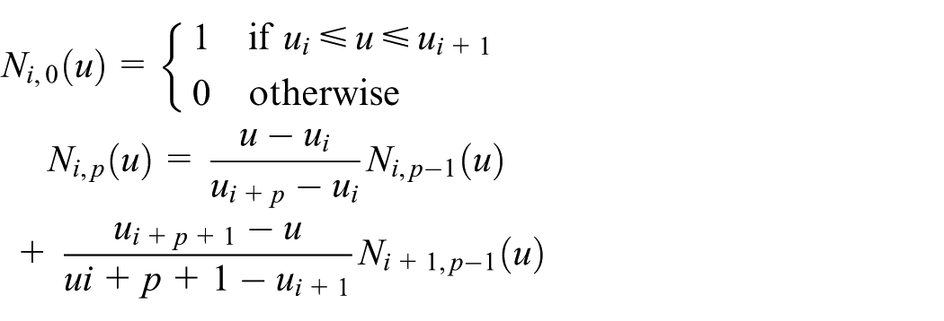
Interpolation of NURBS curve
To generate motion trajectory using the sampled-data interpolation algorithm, the position command at each sampling period

where

Curvature and chord error estimation
Curvature is the most important information in feedrate planning, which is widely used to estimate chord error and contour error. For example, the chord error

where
For parametric curves, the curvature

Real-time feedrate scheduling scheme
In order to generate smooth feedrate profile for both short linear blocks and NURBS curves, a real-time look-ahead feedrate scheduling method is developed. The flowchart of the proposed method is shown in Figure 1. An NURBS curve is pre-interpolated using the proposed Local Fine Pre-interpolation method for critical point detection. After pre-interpolation, the NURBS curve is subdivided into small segments by a set of reference points. The curvature at each reference point is also computed using equation (4) during pre-interpolation. Next, by scanning along the reference trajectory, critical points with local maximum curvature are detected. All the information of each reference point is stored in a buffer, including Cartesian coordinates, curvature, corresponding NURBS parameter value, length of the current segment, estimated chord error, and whether it is marked as a critical point. The look-ahead feedrate scheduling module reads points cyclically from the buffer. By employing the proposed windowed look-ahead feedrate scheduling method, the system is able to keep running smoothly as long as there is adequate trajectory point data for generating a successful feedrate profile in the buffer. Hence, there is no need to pre-interpolate the curve completely before feedrate planning, thereby making the preprocessing stage to be applied for online use. The generated feedrate profile is utilized for fine interpolation to compute position commands in servo period. Parameter compensation method is also applied to avoid feedrate fluctuation.

Flowchart of the feedrate scheduling method.
Feedrate scheduling algorithm
Real-time NURBS curve preprocessing
The primary role of the NURBS curve preprocessing stage is to scan possible feedrate violation points before feedrate profile generation. As described above, the curve is usually pre-interpolated into a set of reference points with constant position increment
Feedrate limit
Four feedrate limitations are considered, including command feedrate, the maximum axial velocity, chord error limits, and centripetal acceleration limit.
First, the feedrate should not exceed the command feedrate

Second, the feedrate is constrained by the maximum axial velocity

where

According to equation (3), the chord error–limited feedrate is given as
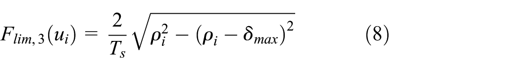
where
Centripetal acceleration is proportional to the square of feedrate
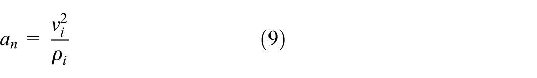
and it is limited by the axial acceleration limits

Therefore, the centripetal acceleration bounded feedrate is given as

The final feedrate limitation for a reference point in the curve is given by

It is possible to add extra feedrate constraints in equation (12).
Acceleration limit
Axial acceleration limits

When scheduling feedrate for an NURBS block, the acceleration constraint

where n is the number of reference points in the NURBS block.
Local fine preprocessing method
To schedule feedrate profiles, it is necessary to find out the critical points with local minimum permissible feedrate from the reference points. However, the reference points are generated with rough interpolation; there is an error between the estimated reference points and the theoretical critical point. To approximate the theoretical critical points more precisely, the given constant increment (or feedrate) should be small enough. But low pre-interpolation feedrate introduces large computational cost to the preprocessing task.
In order to solve this problem, a local fine preprocessing method is proposed, as shown in Algorithm 1. The preprocessor interpolates the NURBS curve with a fast feedrate (e.g. 100 mm/s). Three reference points form a critical region if equation (15) is met
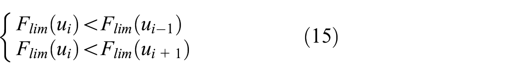

If a critical region
Jerk-limited trigonometric velocity profile
Trigonometric velocity profile has a concise expression of formula, while the widely used S-shaped polynomial velocity scheduling method 11 consists of seven stages and involves more parameters. In this section, the implementation of trigonometric velocity function is presented more concisely and clearly.
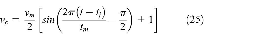
As shown in Figure 2, the velocity function of one velocity transition process is given as equation (16)

which can be simplified to equation (17)

where
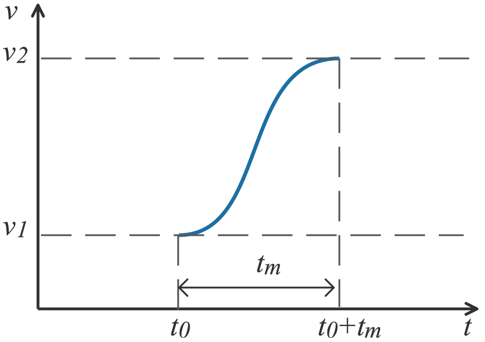
Trigonometric feedrate profile from
The acceleration and jerk functions could be obtained by taking first and second derivatives of equation (17) with respect to time

There is only one variable
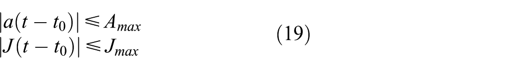
Solving equations (18) and (19) yields the limitations of

Thereby,

Once

To demonstrate the features of the jerk-limited trigonometric velocity profile, the feedrate profile of a

Feedrate profile of a
Consequently, the advantages of the trigonometric feedrate scheduling method are summarized as concise expression of formula, smoother acceleration, and jerk profiles. And the disadvantage is that the production efficiency will be degraded slightly as compared with S-shaped feedrate scheduling method.
Feedrate profile generation for an NURBS block
The NURBS curve is divided into blocks by the critical points. Each NURBS block is taken as an input unit of the feedrate scheduling procedure. Suppose
There are four types of situation one may encounter to schedule feedrate for an NURBS block, as shown in Table 1. The judgment condition is based on the estimated curve length S.
Different cases of feedrate profile generation for each NURBS block.

NURBS: non-uniform rational B-splines.
For Type 1, the NURBS block is long enough and the maximum velocity
For Type 2 and Type 3, the curve block is short and the maximum feedrate is not reachable. There are two approaches to plan feedrate for such an NURBS block. As shown in Figures (b) and (c) in Table 1, approach 1 divides the feedrate profile into two stages: one is a constant feedrate stage, another is an ACC or DEC stage. The uniform segment is always planned at the higher speed end of the NURBS block. The equitations of the first approach is shown in Table 1. The second approach is shown in Figure (d) of Table 1. The feedrate accelerates from
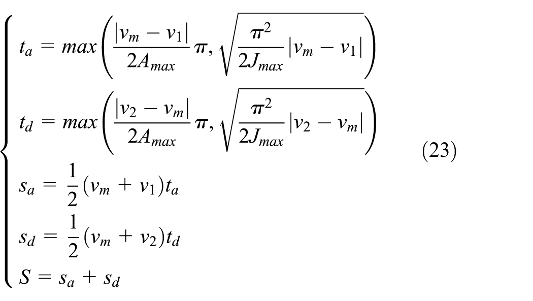
Compared with approach 1, approach 2 takes less time to travel the same NURBS block. However, the feedrate and acceleration fluctuate in a short time, which could possibly lead to machining vibration. Therefore, approach 1 is chosen as the default method when planning feedrate for short curve blocks.
For Type 4, the curve block is too short and the target velocity is not reachable with the limitations of acceleration and jerk, as shown in Figures (e) and (f). To avoid feedrate discontinuity, it is necessary to perform forward look-ahead feedrate modification at each junction of the NURBS blocks. For the case in Figure (e), the start velocity
Windowed look-ahead feedrate scheduling method
In prior researches, the NURBS curve is pre-interpolated completely and all the subdivided blocks are sequentially analyzed by the look-ahead module to determine the feedrate at each joint. This kind of look-ahead method is not suitable for real-time application. In this article, a sliding look-ahead window (SLW)-based feedrate scheduling method is proposed in which the look-ahead process is conducted progressively in real time.
As discussed in the previous section, the purpose of look-ahead is to eliminate violation by adjusting junction feedrate of Type 4 short blocks. However, once the feedrate of a junction is modified, the feedrate profile of the adjacent block should be rescheduled. The look-ahead window should be long enough to cover the travel length of the modified feedrate profile.
It can be inferred from equations (21) and (22) that the maximum travel length of a feed transition happens when decelerating from the largest feedrate to zero
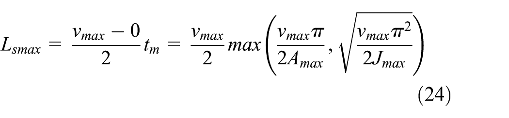
which means that any NURBS block longer than
The diagram of a look-ahead window is shown in Figure 4. A look-ahead window

Diagram of look-ahead window.
The flowchart of the SLW feedrate scheduling method is shown in Figure 5. First, the reference points are pushed into the look-ahead window from the preprocessing buffer. Then the look-ahead window is checked for any non-schedulable short blocks. If a non-schedulable block is detected, feedrate correction is executed before scheduling feedrate. Afterward, according to the existence of critical points in

Flowchart of the SLW feedrate scheduling method.

Different cases of look-ahead feedrate scheduling of SLW.
In case A, there exist critical points in
Feedrate correction for non-schedulable blocks
As described in the previous section, there are two feedrate modification situations for Type 4 blocks in Table 1. The first one is to modify the start velocity when the target velocity is too low and unreachable. The second one is to modify the target velocity when the target velocity is too high. Since the blocks are scheduled sequentially, and the start velocity of the non-schedulable block is also the target velocity of the previous block, the modification of start velocity will cause re-planning of the previous blocks. On the other hand, the second situation has no influence on the previous scheduled feedrate profile. The look-ahead feedrate modification strategy for the first case is discussed as follows.
As the look-ahead window moves forward, a non-schedulable block may be covered by the look-ahead window completely or partly, as shown in Figure 7, where EF is a non-schedulable block and
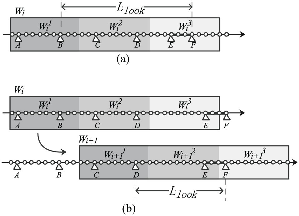
Two cases of non-schedulable block.
In this article, the bisection search algorithm proposed by M Heng and K Erkorkmaz
21
is adopted to correct the junction velocities of the non-schedulable blocks, as shown in Figure 8. Different with Heng and Erkorkmaz,
21
the feedrate search space in this article is [
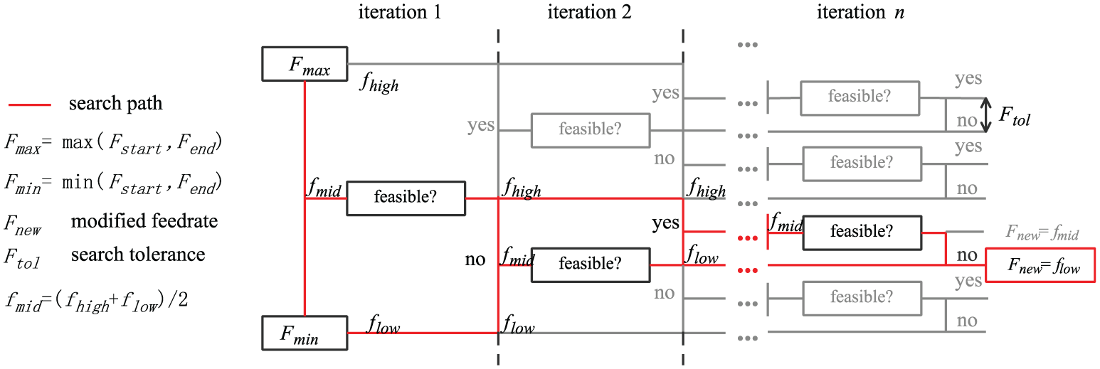
Bisection search algorithm for a feasible feed. 21
By now, using the windowed look-ahead window feedrate scheduling method, a set of consecutive and successful feedrate profile segments are generated and ready to be used for real-time interpolation, although the feedrate profile have not been generated completely.
Terminal error compensation of NURBS blocks
Since the length

Transition point and terminal error compensation.
To compensate the error between

Compensation feedrate profile.
First, the curve length

Consequently, the terminal error of interior NURBS block whose end velocity is nonzero is compensated by continuous interpolation with
Simulation and experimental results
In this section, simulation tests are performed on some NURBS tool paths in order to demonstrate the feasibility and applicability of the proposed feedrate scheduling method. The proposed NURBS preprocessing method and look-ahead feedrate scheduling method are realized using MATLAB language. The simulation platform is an Intel Celeron J1900–based personal computer that runs at 2.0 GHz.
Pre-processing method validation
A trident-shape NURBS curve is employed to test the proposed NURBS preprocessing method. The geometry model and control polygon of the trident shape are shown in Figure 11, and its NURBS parameters are as follows:
Order p: 2;
Knot vector
Control points
Weights

Geometry model of the trident-shape curve.
To clearly demonstrate the advantage of the proposed preprocessing method, only chord error constraint is considered in this experiment. Hence, the critical points are exactly the high curvature points. There are five sharp corners along the trident curve, which are marked as A, B, C, D, and E in Figure 11. By employing the local fine preprocessing method, the critical point parameters and the corresponding curvature values are obtained. The reference points at sharp corner A and curvature profile are shown in Figure 12. Compared to traditional constant feedrate preprocessing method, the proposed local fine preprocessing method generates reference points more densely around the sharp corner, as shown in Figure 12(a) and (c). Hence, the high curvature critical points are approximated more accurately using the proposed method. In Figure 12(b), the estimated curvature values of the critical points A and E are

Reference points at sharp corner A and curvature profiles: (a) constant feedrate preprocessing method when
The computation time of the preprocessing stage is estimated using the MATLAB platform, as shown in Table 2. To achieve the same curvature estimation accuracy as the local fine preprocessing method, the pre-interpolation feedrate of constant feedrate method should be reduced to
Comparison of the results of two preprocessing methods for the trident curve test.

The results show that the presented local fine preprocessing method can significantly improve the curvature estimation accuracy without a large increasing the computation burden. Hence, the feasibility of the presented NURBS preprocessing method is demonstrated.
Look-ahead feedrate scheduling algorithm validation
A WM-shape NURBS curve with both high and low curvature zones is employed to validate the proposed look-ahead feedrate scheduling algorithm. The NURBS parameters of the curve are given as follows:
Order p: 2;
Knot vector
Control points
Weights
The parameters employed for the test are illustrated in Table 3, and they are artificially set according to commonly used values. Note that the feedrate and acceleration limits of each axis are set as different values for verification of the proposed approach. The command feedrate is set to
Parameters used for the simulation test.

The WM-shape curve is shown in Figure 13(a). The feedrate constraints are shown in Figure 13(b). By employing the proposed preprocessing method, 15 critical points are found and the curve is divided into 16 blocks. Some critical points are very close and their tolerant feedrate values change abruptly. The short blocks between these critical points are non-schedulable. By employing the windowing look-ahead and feedrate correction method, a smooth feedrate profile is generated without violating any constraints, as shown in Figure 13(b).

WM-shape curve look-ahead feedrate scheduling test: (a) geometry of the WM-shape curve, (b) feedrate limits and scheduled feedrate profile, (c) X-axis feedrate, (d) Y-axis feedrate, (e) X-axis acceleration, (f) Y-axis acceleration, (g) tangential acceleration, and (h) tangential jerk.
The axial feedrate and acceleration profiles of X-axis and Y-axis are shown in Figure 13(c)–(f), respectively. The tangential acceleration and jerk profiles are shown in Figure 13(g) and (h). All the actual values in terms of axial feedrate, axial acceleration, and tangential jerk are constrained within the set limitations.
Figure 14(a) shows the feedrate profile with respect to time. As can be seen, a short sine-curve feedrate profile is scheduled in order to eliminate the terminal error at the end of the NURBS curve. As shown in Figure 14(b), the feedrate is decelerated to zero at point A. However, the end of the curve is not reached yet. With the compensation feedrate profile applied, extra interpolation points are generated until the end of the curve.
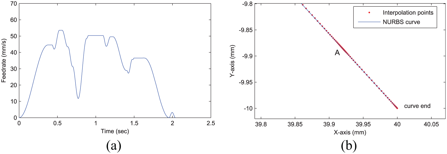
Terminal error compensation: (a) Feedrate profile and (b) interpolation points.
The chord error of each interpolation point is also estimated, as shown in Figure 15(a) and (b). Using the proposed SLW method, the chord error profile is efficiently limited within the preset limitation

Chord error profile: (a) chord error generated with constant interpolation feedrate,
In addition, the parameter compensation method proposed by Yeh and Hsu 22 is utilized to reduce the feedrate fluctuation, as shown in Figure 16. After parameter compensation, the maximum feedrate fluctuation is reduced from 6.691% to 0.035%.
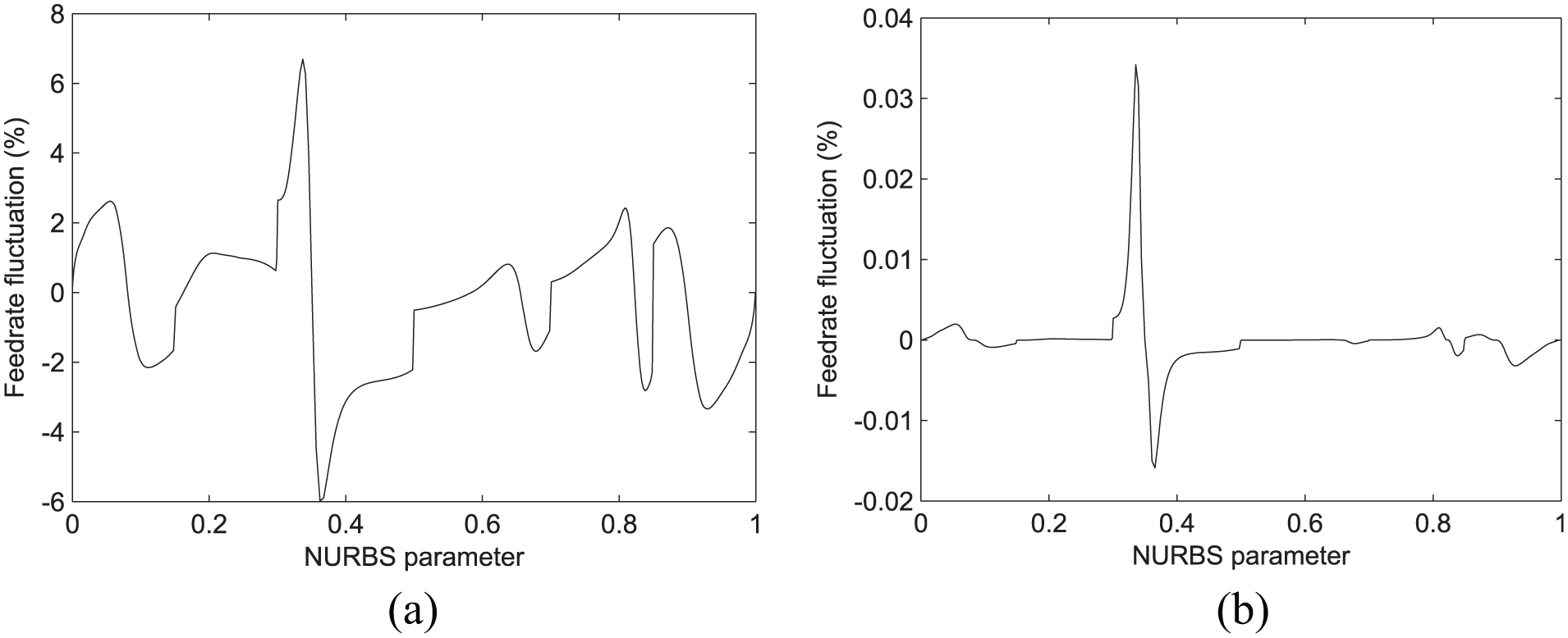
Feedrate fluctuations of different methods for the WM-curve test: (a) first-order Taylor expansion interpolation and (b) parameter compensation interpolation.
Real-time performance evaluation
To verify that the proposed preprocessing, feedrate scheduling algorithm, and real-time interpolation can be run online simultaneously, both the trident curve and the WM-shape curve are tested to evaluate the computational capability. Simulation results are listed in Table 4.
Execution time evaluation of key algorithms

NC: Numerical Control; NURBS: non-uniform rational B-splines.
Take the trident curve for example. The length of a look-ahead window is
As shown in Table 4, the Adaptive Simpson’s method takes a lot of execution time with a tight tolerance adopted. However, with the terminal error compensation algorithm applied, there is no need to evaluate the length of an NURBS block accurately. Hence, a loose length tolerance could be adopted to avoid unnecessary computing burden.
Analyses and comparisons
The butterfly-shaped curve is widely adopted in many researches, and some comparison data between the dynamics-based interpolation algorithms with look-ahead (DBLA) method 6 and the NURBS interpolator with feedrate scheduling (NIFS) method 20 are provided in Liu et al. 20 In order to further evaluate the proposed SLW method via comparing with DBLA and NIFS method, the butterfly curve is chosen as the test case in this study.
The geometry model and critical points of the butterfly curve are shown in Figure 17. The feedrate profile generated by SLW algorithm is shown in Figure 18. The scheduled feedrate profile of SLW is a little different with DBLA and NIFS, because different feedrate limitations are considered. Axial velocity and axial acceleration are constrained in this study.

Geometry model of the butterfly curve.

Feedrate, chord error, and feedrate fluctuation profiles generated by SLW.
Some statistical comparisons between SLW and the two methods are shown in Table 5. Since each axis of the machine tool has different kinematic performance in this study, simply using the geometrical curvature of the tool path is not an adequate quantity to identify the “critical points.” With axial velocity/acceleration limits considered, more critical points are identified by the SLW method than DBLA and NIFS. As a result, the scheduled feedrate around the extra critical points is reduced, and it takes more machining time.
Statistical comparisons.

DBLA : dynamics-based interpolation algorithms with look-ahead method; NIFS: NURBS interpolator with feedrate scheduling; NURBS: non-uniform rational B-splines; SLW: sliding look-ahead window.
The NIFS method generates less reference points and consumes less computational time in the preprocessing stage using the interval subdivision algorithm. However, the interval subdivision algorithm causes the whole curve to be preprocessed and scheduled at once. The feedrate profile is fixed after generation, and it needs to be rescheduled when a machining pause operation is requested. With the SLW algorithm, the look-ahead length is short; it is easier to response to machining “PAUSE” or “STOP” commands by appending zero velocity reference point to the latest look-ahead window.
Machining trial
To further assess the feasibility of the proposed feedrate scheduling method, a machining experiment is carried out on a three-axis milling machine. The machine tool is controlled using the LinuxCNC, which is an open source CNC system. LinuxCNC is extended to support Industrial Real-Time Ethernet protocol EtherCAT, which is supported by the servo drivers on the milling machine. The proposed NURBS preprocessing method and windowing look-ahead feedrate scheduling method are developed as a real-time component of LinuxCNC and run cyclically in the kernel space. The interpolated position commands are transferred to the servo drivers through EtherCAT bus. In order to guarantee that the interpolation algorithm can be completed in real time, the computation time for calculating each reference point and the feedrate at each point are recorded. It is found that the maximum calculation time is

Machining trial: (a) the milling machine and (b) the machined workpiece.
Conclusion
In this article, a real-time NURBS feedrate scheduling method with chord error, axial feedrate, acceleration, and jerk limitations is proposed to make balance between the machining efficiency, precision, and computational complexity. This method contains an online preprocessor and a look-ahead feedrate profile generator. In the preprocessing stage, a local fine pre-interpolation method is developed to accurately estimate the feedrate limitation profile by reducing pre-interpolation feedrate in feedrate-sensitive regions. After preprocessing, acceleration/deceleration start/end point parameters and the corresponding tolerant feedrate values are obtained and stored in the buffer. A windowed look-ahead feedrate scheduling method is proposed to generate smooth feedrate profile for the buffered NURBS segments. A smooth feedrate profile could be generated with sufficient look-ahead travel length in the buffer, which enables that the preprocessing and feedrate planning to be performed progressively in real-time domain. Simulation and experimental results validate the feasibility and advantages of the proposed method. The presented method is highly applicable in open CNCs because the proposed algorithms are computationally efficient and robust as verified in the experimental results.
In this work, only chord error, axial feedrate, acceleration, and jerk limitations are considered. To further improve the machining precision, the feedrate scheduling method with contour-error and drive constraints should be studied in future research.
Footnotes
Acknowledgements
The authors wish to thank the anonymous reviewers for their comments, which led to improvements of this paper.
Handling Editor: Tatsushi Nishi
Declaration of conflicting interests
The author(s) declared no potential conflicts of interest with respect to the research, authorship, and/or publication of this article.
Funding
The author(s) disclosed receipt of the following financial support for the research, authorship, and/or publication of this article: This work is supported by the National Natural Science Foundation of China (51805116) and the National Science and Technology Major Project of China (2013ZX04013-011-09).