
Abstract
The integral impeller is a complex part characterized by highly curved surfaces. Modeling and interpolation methods for manufacturing integral impellers are currently the subject of intensive research. In this study, to represent the shape of the ruled-surface blades, third-order non-uniform rational B-splines are constructed from data points for the hub and shoulder on the pressure and suction sides of the blade. Various methods for determining the tool axis vector offset and the location of the tool center for a cylindrical ball cutter are developed and verified with simulations of machining operations. To obtain a smooth interpolation and high accuracy in machining, a third-order non-uniform rational B-spline interpolation algorithm for ruled-surface blades is developed. This method can create a smooth transition between the hub and the blade shoulders. The method is implemented in an open-architecture computer numerical control controller. Simulations and experimental tests of machining tasks are performed to verify the non-uniform rational B-spline interpolation method. The test results show that this interpolation technique can produce a smooth and continuous path along the axes of motion. The new technique has the advantages of requiring fewer lines of numerical control code and producing higher machining accuracy.
Keywords
Introduction
The integral impeller is representative of parts with complex surfaces, having thin, highly curved blades with narrow spaces between the blades. Integral impellers can include ruled-surface blades or free-surface blades depending on the blade shape. A ruled-surface integral impeller is shown in Figure 1.
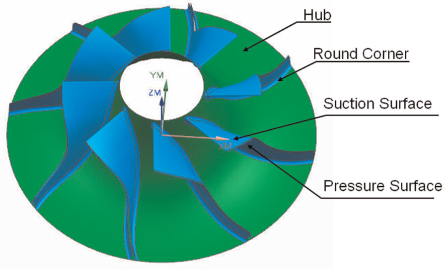
A ruled-surface integral impeller.
The blades of such an impeller are thin, and their curvature varies significantly between the leading and trailing edges. If the cutter axis is not varied uniformly in the machining process, the part will contain defects, 1 which will affect the mechanical properties and performance of the impeller. This requirement makes machining an impeller difficult. A cylindrical or conical cutter and flank milling are typically used for machining ruled-surface impellers. This method is highly efficient and results in a good surface quality.
Computer-aided manufacturing (CAM) technologies for ruled surfaces have been extensively studied. Chen 2 developed a ruled-surface milling algorithm for cylindrical cutters that considers efficiency in the rough machining and the finishing processes. A three-step tangent optimization method has been presented to reduce machining errors in side milling. 3 Kim and Yang 4 presented a curved surface offset method for three-axis milling with various cutters. Haiyan et al. 5 studied the influence factors of the cutting force to optimize the machining parameters in milling. Lee and Suh 6 proposed a tool trajectory planning method without interference for ruled surfaces. This method avoids interference with the entire cutting tool by varying the tool axis angle and the tool offset distance.
Free-form surfaces can be easily modeled with various methods, but recently, the standard interface between computer-aided design (CAD) and CAM has been criticized for its shortcomings, including the voluminous amount of segment data that must be generated by the CAD system and transmitted to the computer numerical control (CNC) machine and the tradeoff between accuracy and efficiency imposed by this process. To remedy this situation, several authors have proposed various interpolation methods. For example, a cubic curve interpolation scheme for the CNC machining of free-form surfaces has been proposed. 7 A new format for tool path polynomial interpolation was developed for five-axis machining. However, decreasing the number of control points and clearly identifying the points of discontinuity must be performed to simplify the interpolation. Finding the best tool path that produces the required qualities and simplifies the dynamics of numerical control remains an issue to be addressed. 8 The flank milling of free-form surfaces has been proposed to generate the tool path while satisfying accuracy requirements and two constraints. However, this method is based on various geometric characteristics, including the cutter surface, the part surface and the constraint surface. In certain cases, it is difficult to mathematically describe the convergence conditions. 9 A trajectory generation method based on curvature theory has been proposed for the five-axis machining of free-form surfaces. The Ferguson geometric modeling technique is used to represent the tool trajectory. However, this method has been tested only with simulations. Furthermore, this method cannot be implemented on a conventional numerical control (NC) controller, and an open platform, that is, an open-architecture controller, must be used. 10 A series of G-codes for communicating spatial circular paths, cutter offsets along free-form curves and revolved surfaces to CNC machines have been proposed. Various tests using a PC-based three-axis CNC milling machine have confirmed the adequacy of these algorithms under realistic cutting conditions. 11
Parametric curve interpolation presents many advantages compared with linear and circular interpolation methods. For example, parametric curve interpolation can reduce the data transmission load and contour approximation errors. In addition, this method can improve the smoothness of the cutter axis vector and decrease machine tool vibrations, which improve the quality of the final product. Tsai et al. 12 introduced an non-uniform rational B-spline (NURBS) interpolation algorithm that maintains a constant cutting speed, which is appropriate for machining NURBS surfaces with a ball-end cutter in a three-axis machine tool. Tikhon et al. 13 developed a parametric curve interpolation algorithm that ensures constant material removal and uses a constant speed parameter curve interpolation to control the cutting. Fleisig and Spence 14 used a fifth-order parametric spline to interpolate the position vector about five coordinate tool trajectory and constructed an orientation vector interpolation curve on the unit sphere to achieve real-time interpolation. Langeron et al. 8 used the same parametric B-spline interpolation for both the position vector and the orientation vector and presented the corresponding B-spline interpolation instruction format. Peng et al. 15 presented a NURBS interpolation algorithm that includes the kinetic characteristics of the machine.
A review of the literature reveals that many theoretical studies on ruled-surface and free-form surface machining with various types of curve or surface interpolation methods have been performed. Few studies have applied NURBSs to the actual machining of ruled surfaces in five-axis milling, whereby the machining parameters must be considered. There are three problems that must be addressed in this methodology: the existing CAM technology used to plan the trajectory for cutting a ruled-surface blade, interpolating between the NURBS curves for the hub and the shoulder on the suction or pressure surfaces and implementing the method in practice on a CNC controller.
The objective of this study is to address these problems in the machining of ruled-surface impeller blades. First, a NURBS interpolation algorithm that can smoothly coordinate the position curve and the orientation curve given the tool axis vector and the tool center point is developed. A third-order NURBS interpolation method for the ruled surfaces is developed. This method requires 20 data points, 10 points for the hub and 10 points for the shoulder, for either the pressure surface or the suction surface. Second, the NURBS interpolation algorithm is implemented in an open-architecture CNC controller. Third, the parameters of the developed algorithm are analyzed for impeller slotting and finishing operations. Fourth, an impeller is machined to verify the feasibility of the proposed method.
Extraction of the feature points of the hub and shoulder of a ruled-surface blade
Let
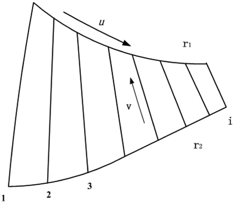
Diagram of a simple ruled surface.
The ruled surface can be represented as shown in equation (1)
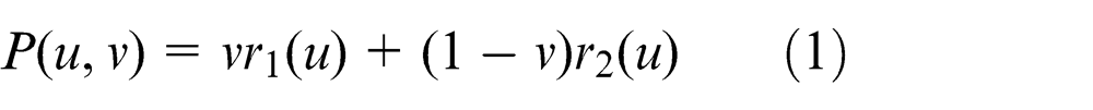
In equation (1), u and v are the nodes of the curves. The kth-order NURBSs r 1(u) and r 2(u) can be represented as a piecewise-rational polynomial vector functions given by equation (2)
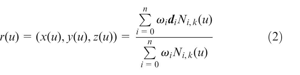
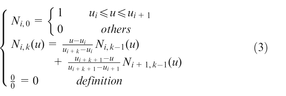
where k is the order of the NURBS, d i are the three-dimensional control points that form the control polygon with sequential connections, ω i are weighting factors chosen such that ωi > 0 for i = 0 and n and ωi ≥ 0 for 0 < i < n, and Ni,k (u) are B-spline basis functions. The basis functions Ni,k (u) are given by the de Boer–Cox recursive formula shown in equation (3)
A NURBS is completely described by the control points, the weighting factors and the node vector. The hub and the shoulder curves can be defined with NURBS for both the suction and pressure sides of the impeller blades. To realize back-calculation of NURBS, only 10 data points are required for each curve in the proposed NURBS interpolation algorithm, specifically 40 data points in total are required for both the hub and the shoulder on both sides of the blade, which can both simplify the blade modeling and meet the C 2 parameter continuity. If a ruled surface is modeled with the CAD/CAM software Unigraphics (UG; Siemens PLM Software, Plano, TX), an example of 10 data points extracted with the software for a blade shoulder, to realize NURBS fitting and interpolation, is shown in Figure 3.
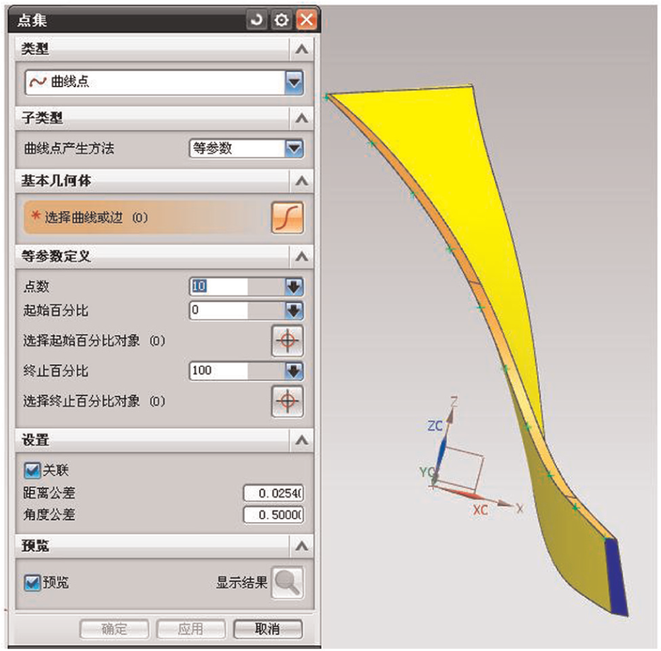
Definition of the data points for the shoulder on the pressure surface in UG.
In Figure 3, the extracted method of data points is set as the equal parameter method, and the point number is set as 10. Then, three-dimensional coordinates of 10 data points can be read and saved with a text format by a grip file in UG.
Calculation of the NURBSs for the hub and the shoulder
Determination of the node vector
The vector
The internal nodes for the NURBSs can be calculated using the Hartley–Judd method. The node interval length in the domain can be obtained using equation (4)
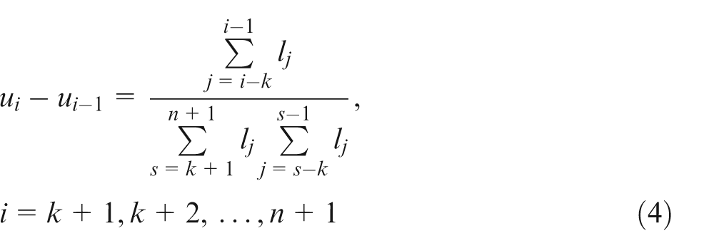
where lj
is the length of each side of the control polygon and
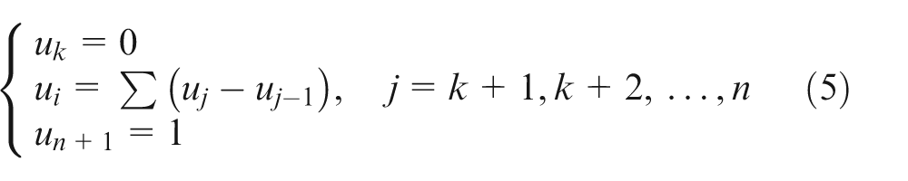
The node values can be calculated from equation (5)
Back-calculation of NURBSs
Determining the node vectors and the control points to construct the interpolation curve from the known data points is referred to as back-calculation. In practice,
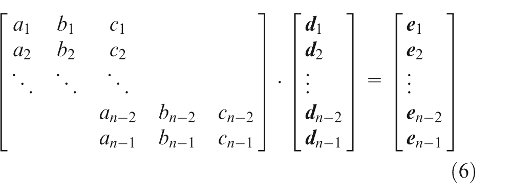
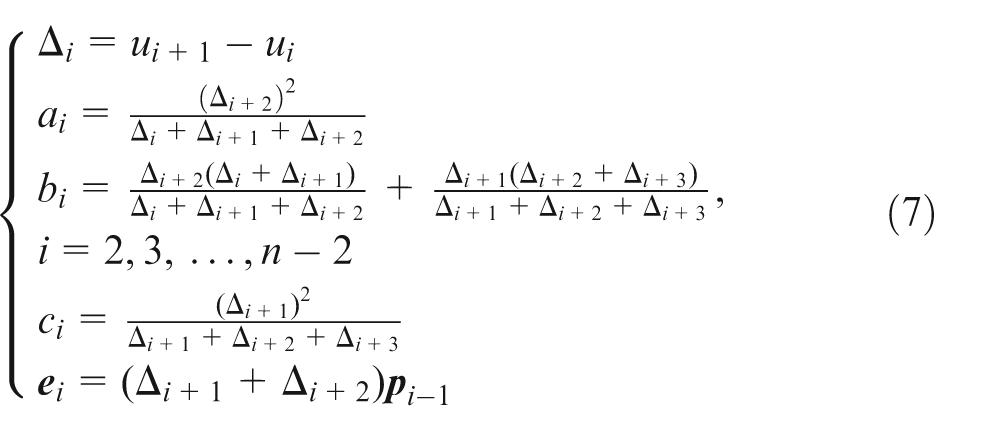
There are n − 1 equalities in equation (6), where the coefficients are given by equation (7), except for e 1 and e n − 1; these two coefficients can be determined from the end conditions corresponding to either a free endpoint or a tangent vector
The solution to equation (6) provides n − 1 control points. The NURBSs should pass through the first and last points. Specifically, the control points at the ends are equal to the first and last data points. As an example, the control points for the NURBS for the shoulder of the suction surface are shown in Figure 4.
Twelve control points obtained for the NURBS for the shoulder of the suction surface.
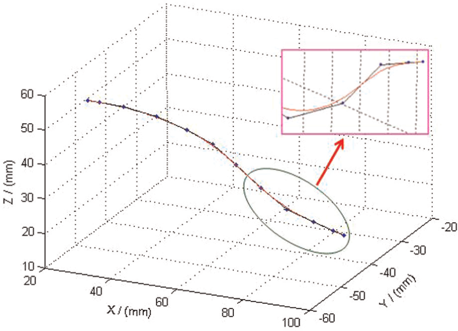
After the node vector and the control points are computed, the NURBS can be constructed. NURBSs for the hub and shoulder of the suction surface are shown in Figure 5.
NURBSs for the hub and shoulder of the suction surface of an impeller blade.
In Figure 5, the points indicated on each NURBS are the data points chosen from the blade. NURBSs were obtained for the hub and shoulder on the suction surface.
Interpolation of the ruled surface for an impeller
The impeller machining process consists of slotting, slot expansion, finishing and smoothing. These steps are defined as follows:
Slotting. The main task in slotting is to form rough channels between the blades with uniform allowances for the blades. Large cutters should be used to improve the cutting conditions and the cutting efficiency.
Slot expansion. A ball-end, straight-shank cutter is normally used for slot expansion. The cutter expands the slots from the inside to the outside, starting from the slot position. The hub surface is formed at the same time. The key to slot expansion is to accurately define the tool movement ranges using channels on both sides of the blade surfaces to prevent the cutter from cutting into the blades on either side.
Blade finishing and smoothing. Blade finishing produces a high-quality surface and is one of the most important steps in machining an integral impeller. The purpose of smoothing is to create smooth transitions between the hub and the blade roots.
Calculation of the cutter axis vector and the cutter center for blade surface flank milling
It belongs to the mold processing for the channel machining of the impeller. This channel is bounded by the blade and the offset surface of the hub. A blade has two surfaces: the suction surface and the pressure surface. Two sets of intersecting lines must be calculated: the lines between the suction surface and the offset hub surface and between the pressure surface and the hub offset surface. The most important point is to ensure that the tool axis remains between the two offset surfaces to avoid cutting on the sides.
In Figure 6, R is the cylindrical tool radius; P 1 and P 2 are points on the shoulder and the hub, respectively; n 1 is the unit normal vector at P 1; n 2 is the unit normal vector at P 2; C 1 and C 2 are points on the lines n 1 and n 2, respectively and C 1 C 2 is the direction of the tool axis when the straight line P 1 P 2 is machined. Let |P 1 P 2| = L and let |P 1 C 1| = |P 2 C 2| = d, where d is unknown.
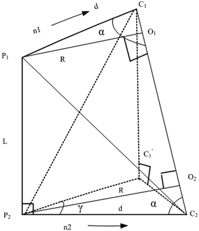
Calculation of the tool axis vector for the offset surface.
The equality |P
1
O
1| = |P
2
O
2| = R must be satisfied to ensure that the tool makes contact at P
1 and P
2, where R is the tool radius. The line from
When milling the blades, the blades are usually cut with the side of the tool (i.e. flank milling), and the hub surface is cut with the end of the tool. If the tool is a ball-end cutter, the cutter center will be at the intersection point between the tool axis vector and the offset hub surface. Both quadrilateral 16 and triangular 17 methods have been presented to solve for the tool center point coordinates. Both methods transform the problem into one of calculating the point of intersection between the tool orientation vector and the offset surface of the hub.
Referring to Figure 7, the NURBS h 1 is obtained after offsetting the hub surface by the tool radius R in the direction of the hub surface normal vector. The offset ruled surface is denoted as R 1 and is defined by h 1 and the shoulder offset curve s 1. For the surface R 1, the direction of v is defined by the tool axis vector K, and the direction of u is defined by s 1 and h 1. The node vector for v is computed according to the equal parameter interval. If the node is (u, v) on the surface R 1 at a given time, the tool center point vector P c can be calculated using equation (1), as shown in equation (8)
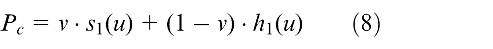
Cutter location calculation for ruled-surface flank milling.
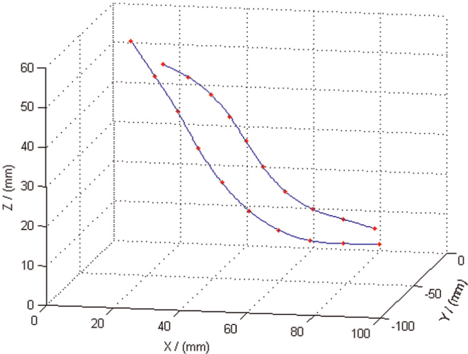
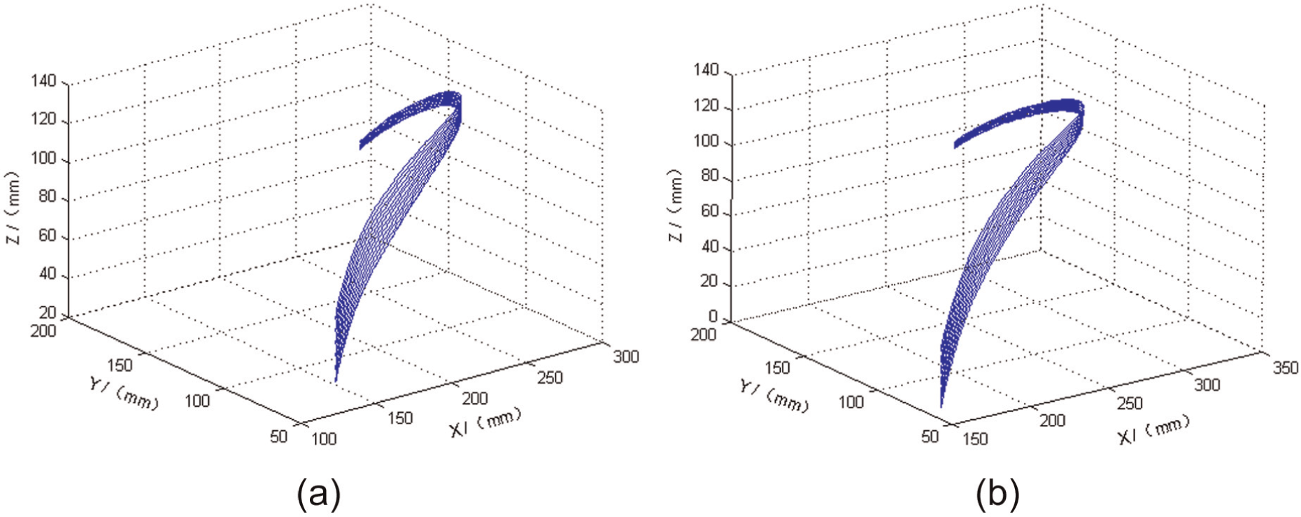
For slot expansion, the tool center point trajectory was determined with the aforementioned method for a ruled-surface blade and is shown in Figure 8.

Tool center point trajectories for slot expansion: (a) suction surface and (b) pressure surface.
In Figure 8, the tool moves back and forth, making 12 passes for each surface. All of these parameters will depend on various factors such as the type of tool and the blade size.
High-precision interpolation for a ruled-surface blade
When a ruled-surface impeller is machined on a five-axis machine, the tool path mode should first be determined; then, the position vector and the orientation vector should be calculated based on the NURBS interpolation. Usually, data sampling interpolation methods are used to interpolate the position curve. Based on the given feed rate in the NC code, the interpolation cycle time (update rate) and the feed rate ratio, the work-piece contour curve is divided into sections. Then, the increment for each axis of motion is computed according to the interpolation step to obtain the coordinates of the target points. It is critical for the five-axis interpolation about the orientation curve’s real-time discrete. The motions in the linear and rotational axes must be coordinated. The accuracy of the machining process directly depends on the method used to interpolate the orientation curve. In this study, the shoulder geometry defines the orientation curve and the hub geometry defines the position curve.
In the process of interpolating the hub curves, the curve parameters at each interpolation update are calculated by the interpolation algorithm based on a Taylor series expansion. After these values are obtained from the curve equation, the position vector is obtained. Assume that the parametric equation of the hub curve is as shown in equation (9)
where the parameter u is a function of time t. The corresponding parameter is
The chord error is the main source of position errors and must be minimized. The chord error for the parametric curve is shown in Figure 9.
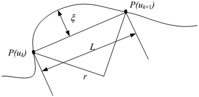
Chord error for the parametric curve.
In Figure 9,
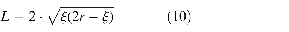
The implementation process for a Taylor series using the chord error is as follows. First, the interpolation path length
A second-order interpolation algorithm can be obtained for the parameter u using equation (11), which is a Taylor series expansion, that is
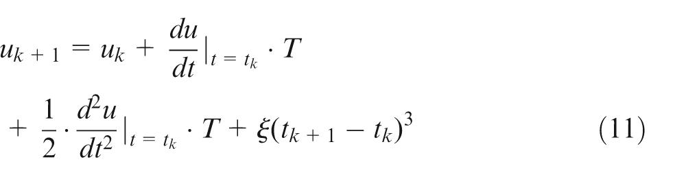
where
Let V be the feed rate. Then, as shown in equation (12), V can be obtained from the time derivative of the curve
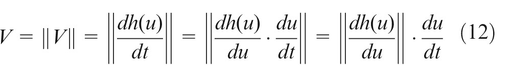
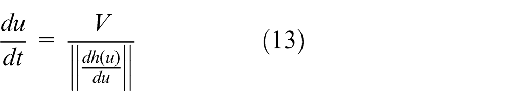
The first derivative of u with respect to t can be expressed as in equation (13)
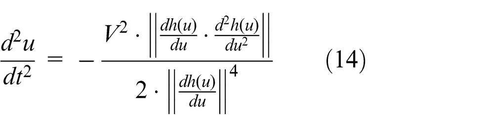
The second derivative of u with respect to t can be obtained as shown in equation (14)
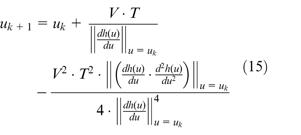
Substituting equations (12)–(14) into equation (11), the second-order interpolation algorithm based on a Taylor series expansion can be obtained as in equation (15)
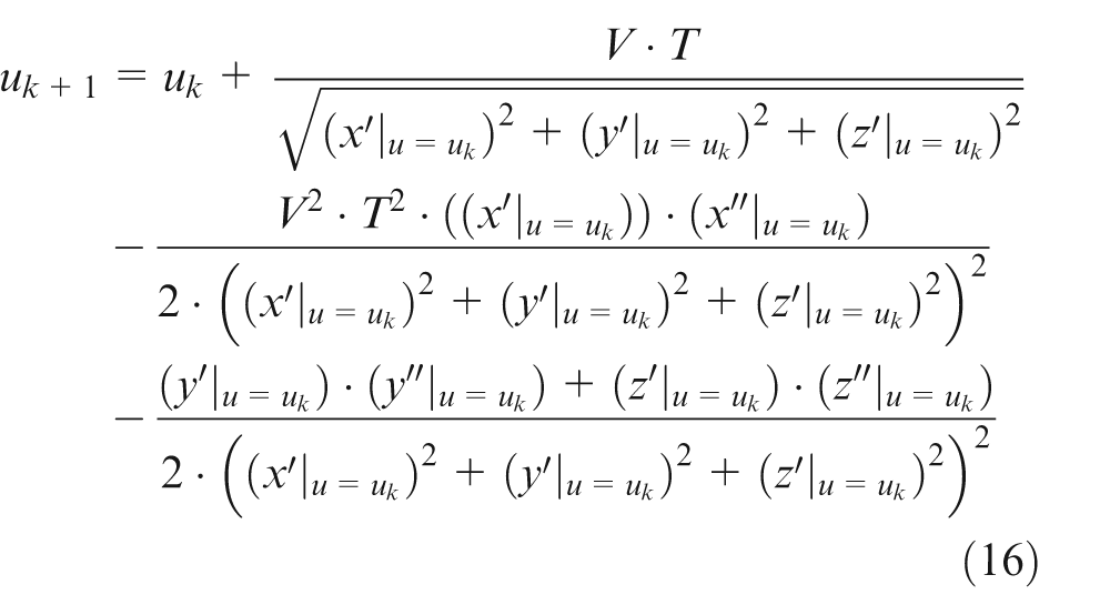
Substituting, the final result is equation (16)
Assume that the parameter value is u
k + 1 after the interpolation. Substituting this value into equation (9), the position vector
Real-time control of the tool requires the computation of the tool orientation vector at each update of the interpolation. Let
First, the node vector
Second, the node vector
Finally, when the node
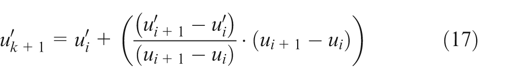
Equation (17) synchronizes the movements along the translational and rotational axes and is based on the node mapping relationship between the position curve and the orientation curve.
After the calculation of the orientation curve node is complete, the results are substituted into equation (9) to obtain the shoulder curve interpolation point
Transformation from the work-piece coordinate system to the machine coordinate system
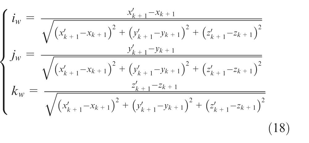
Typically, in five-axis CNC machining, relative processing information of the tool trajectory is executed to finish the interpolation, which is in view of the machine tool coordinate system with the controller’s interpolation unit. Hence, the tool trajectory information generated in the previous section cannot be used directly by the NC machine. To solve this problem, the position and orientation vector information must be transformed to match the specific machine tool structure. This transformation is performed using inverse kinematics. For a double-turntable five-axis CNC machine tool, the transformation is given by equations (19)–(21)
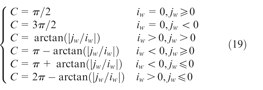
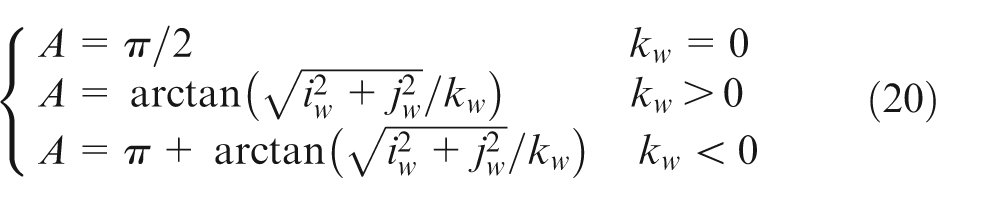
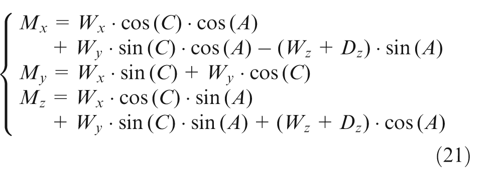
In equations (19) and (20), A and C are the rotation angles about the X-axis and the Z-axis, respectively. In equation (21),
With these equations, the layered slot machining trajectory is transformed from the work-piece coordinate system to the machine coordinate system; the results are shown in Figure 10.
Transformed layered slot expansion trajectory: (a) suction surface and (b) pressure surface.
Implementation of the interpolation strategy in an open-architecture controller
The NURBS interpolation strategy developed for the ruled-surface integral impeller was implemented in an open-architecture CNC controller based on the American Open Modular Architecture Controller (OMAC) standard. The function module structure of the OMAC was used for the CNC controller. The modules and their relationships are shown in Figure 11.
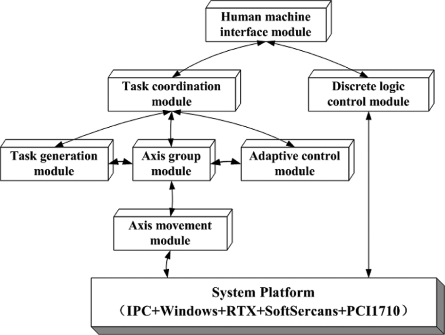
Architecture of the controller with the NURBS interpolation function.
The open-architecture controller consists of a human–machine interface module, a task generation module, a task coordination module, an adaptive control module, a discrete logic control module, an axis group module and an axis movement module.
The human–machine interface module is responsible for the interaction between the operator and the controller, and its main tasks are to set the system parameters before or during operation. The task generation module parses the part processing program files and extracts the necessary information to generate the motion commands and the logic control commands with the motion information. The task coordination module is responsible for coordinating and scheduling the internal modules to assign the tasks. The NURBS interpolation and the inverse kinematics transform are performed in the axis group module, and the results are output to the axis movement module at each interpolation update. The axis movement module performs the functions of position and velocity control after receiving the commands from the axis group module. The adaptive control module receives feedback information from the PCI1710 data acquisition card and is responsible for computing the servo control law and various control strategies. The discrete logic control module is responsible for the Boolean operations related to the external inputs and the internal state variables to obtain the outputs and the internal state variables and control any external input or output devices.
The human–machine interface module and the task generation module are not executed in real time, and they were developed with the Component Object Model to execute the non-real-time tasks. The other modules were implemented as real-time dynamic link libraries to execute the real-time tasks in the Real Time Extension (RTX) environment. The operational and executable interfaces are provided by all of the modules. The function applications and the technical implementations are separate, which enhances the reusability of the modules.
Processing experiment and validation
The format of the NC program for the NURBS interpolation algorithm is shown in Figure 12.
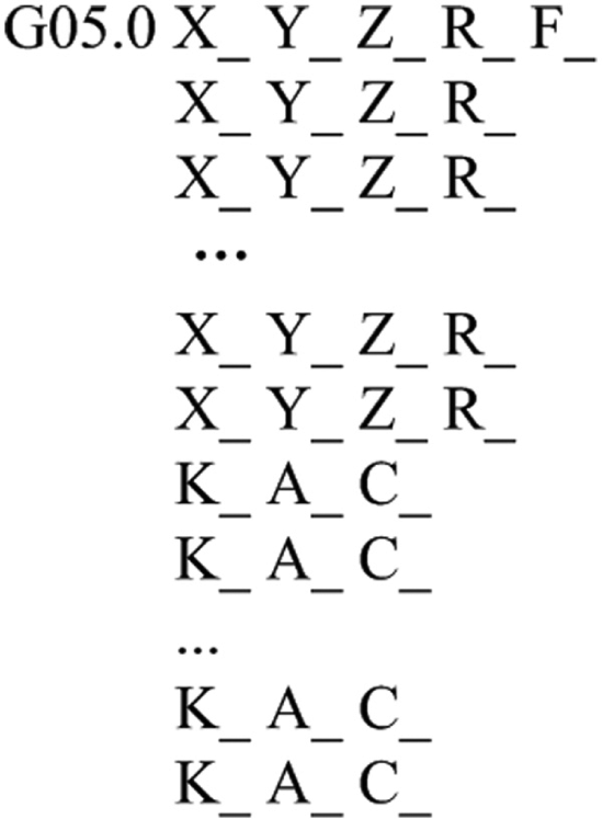
Format of the NC program for the NURBS interpolation algorithm.
In Figure 12, G05.0 is the ready instruction, and the controller reads the subsequent spline information to perform the interpolation. The variables X, Y and Z specify the control points of the position spline, R is the weighting coefficient corresponding to the control points, F gives the feed rate command, K specifies the node and A and C specify the rotation angles of the machine tool.
To verify the correctness of the proposed NURBS interpolation function, the slotting operation for the ruled-surface integral impeller was used as an example. The NC program for the NURBS interpolation algorithm for a single process requires 22 lines, and the linear interpolation requires 51 lines. The NC program is 56.86% smaller than the standard linear interpolation program. The VERICUT environment was used to simulate the slotting operation, and an example is shown in Figure 13.
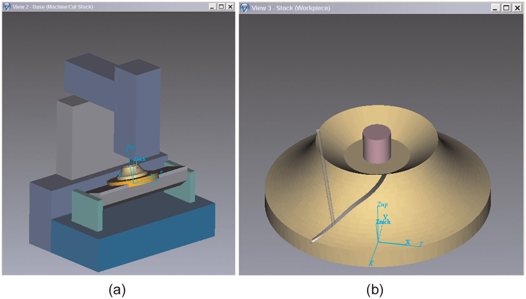
Simulation of the impeller slotting operation in the VERICUT environment: (a) in the machine tool coordinate system and (b) in the work-piece coordinate system.
The controller interpolation algorithm was coded in C++ using the NURBS interpolation strategy. Plots of the displacement, the velocity and the machining error for a single slotting operation for the integral impeller are shown in Figures 14 and 15, which are realized by the simulation program written in C++. In the simulation, the feed rate was 600 mm/min, and the interpolation cycle time was 0.0025 s.
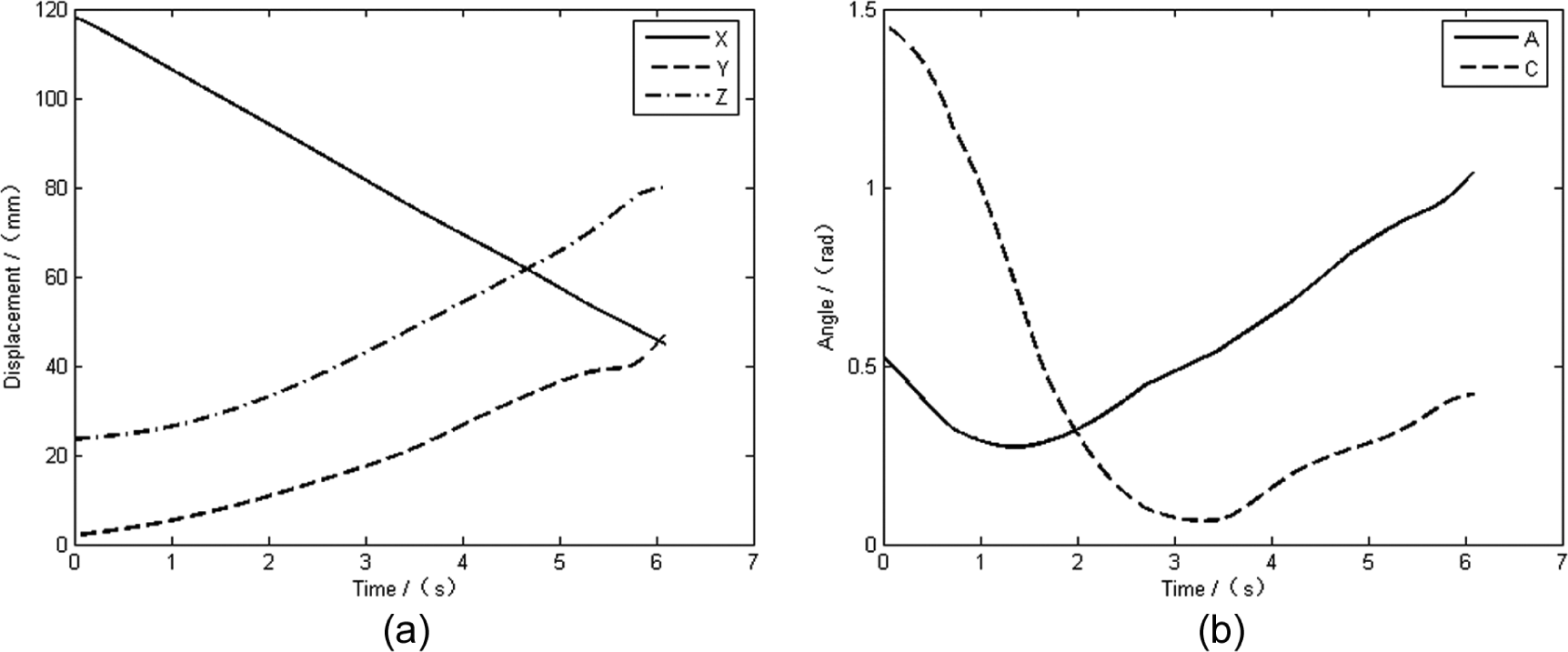
Machine tool displacements: (a) translational axis displacements and (b) rotational axis displacements.
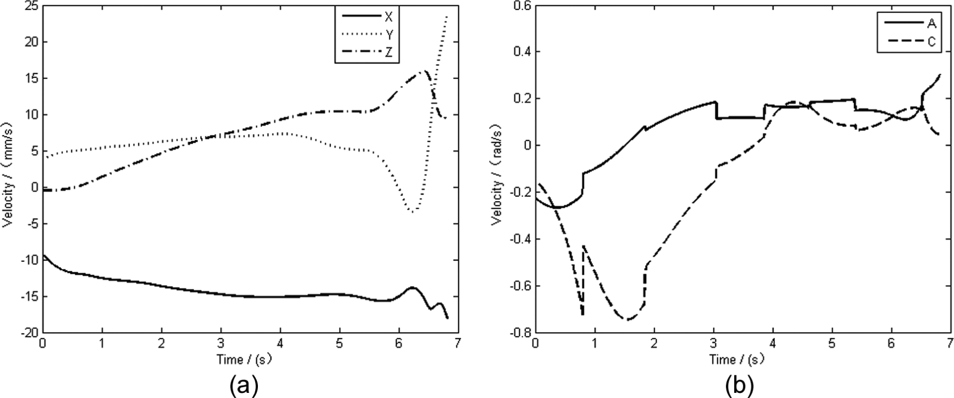
Machine tool speeds: (a) translational axis speeds and (b) rotational axis speeds.
As shown in Figures 14 and 15, the speed along each axis of the machine tool varies continuously, and there are very few large impacts. Next, the slot expansion operation was simulated. The layered slot expansion trajectory for a single blade is shown in Figure 16.
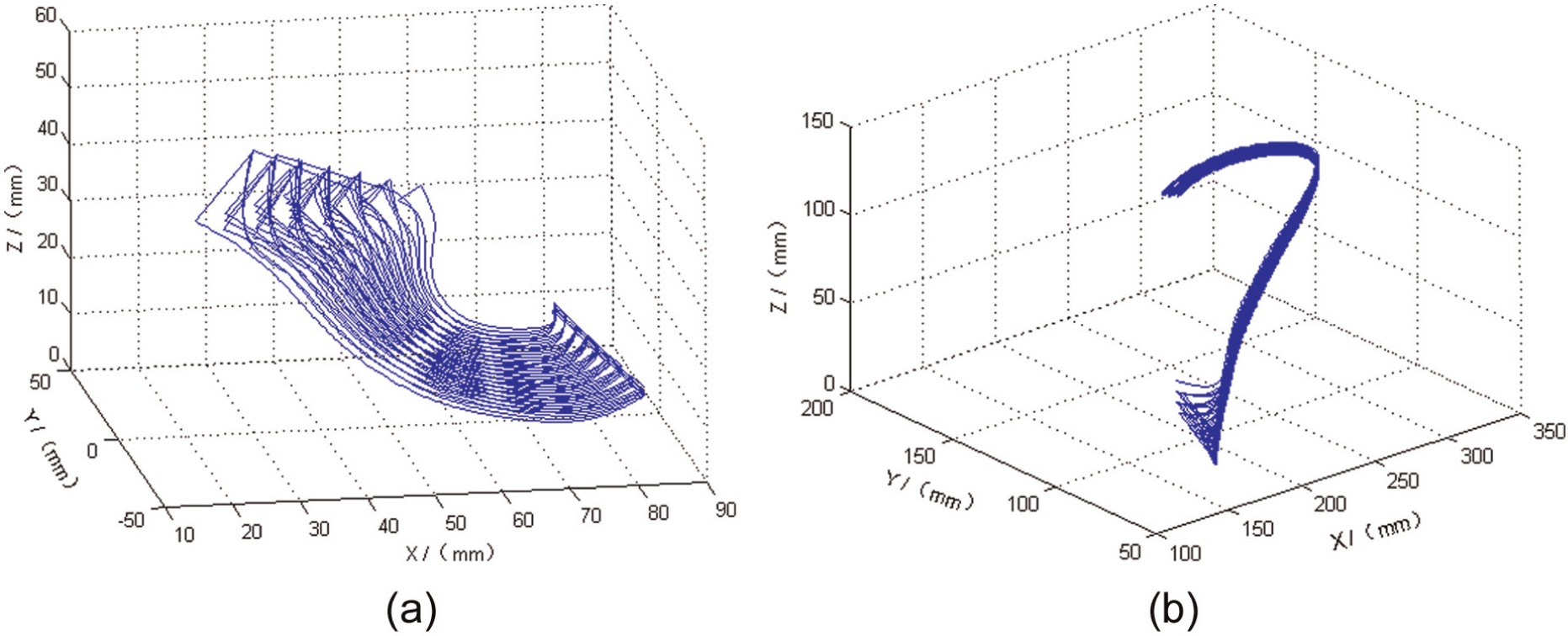
Layered slot expansion trajectory: (a) in the work-piece coordinate system and (b) in the machine tool coordinate system.
The finishing trajectory for one blade is shown in Figure 17.
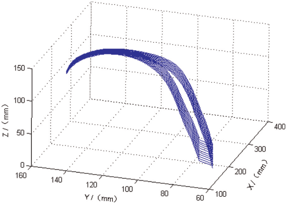
Finishing trajectory for a single blade in the machine tool coordinate system.
The open-architecture controller was tested by machining a ruled-surface integral impeller on a CNC machine. A photograph of the actual machining process is shown in Figure 18.
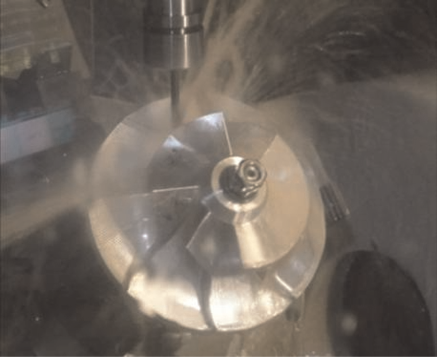
Machining an impeller using the NURBS interpolation function.
In the test, ball-nosed end mills were used, where the radii for slotting, slot expansion and finishing were 6, 6 and 3 mm, respectively. The CNC controller interface used in the test is shown in Figure 19, and a plot of the rotational axis displacements in the finishing operation is shown in Figure 20.
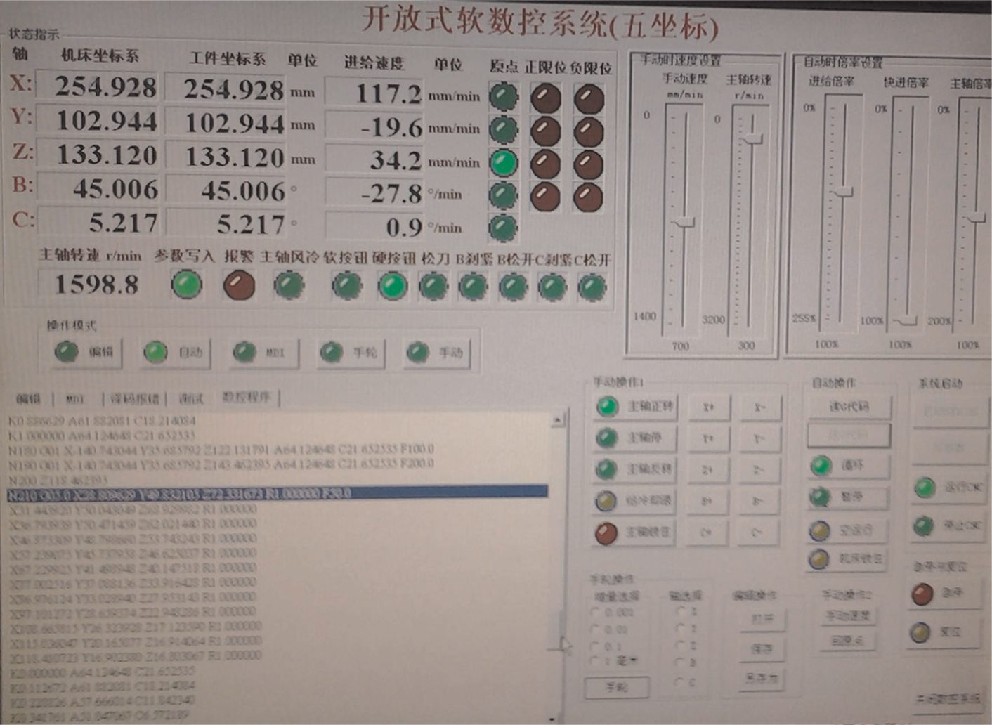
NURBS application interface in actual operation.
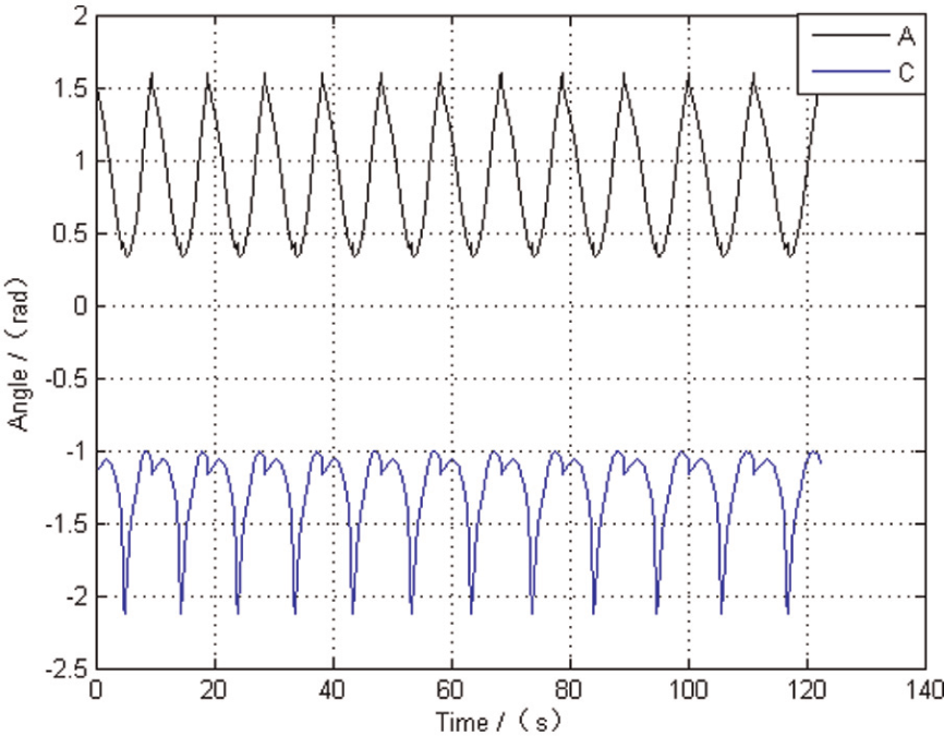
Rotational axis displacements of the blade for the finishing operation.
The actual parts machined using linear interpolation and the NURBS interpolation are shown in Figure 21.
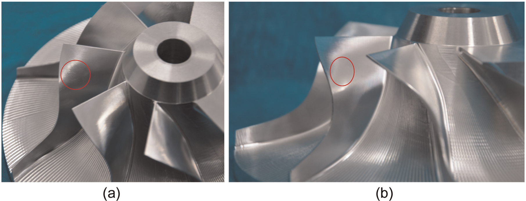
Comparison of blades machined with two interpolation methods: (a) linear interpolation and (b) NURBS interpolation.
Figure 21 shows that the suction surface is smooth and without vibration marks with the NURBS interpolation algorithm, unlike the blade machined with linear interpolation. The distribution of the machining errors on suction surface for the NURBS interpolation is shown in Figure 22.
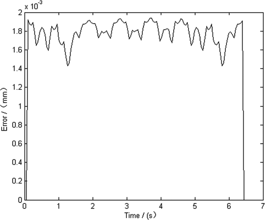
Machining errors for the suction surface with the NURBS interpolation algorithm.
Figure 22 shows that the machining error varies as the curvature of the ruled surface changes. However, the maximum error is only approximately 0.0019 mm; therefore, the machining accuracy is higher than that with linear interpolation. The results show that the NURBS interpolation algorithm is feasible and effective.
Conclusion
To achieve the high-precision machining of a ruled-surface integral impeller, an interpolation strategy based on NURBSs was developed in this study. The following conclusions can be drawn:
The NURBSs can represent a ruled-surface impeller blade with fewer data points than traditional methods. The node vectors for the curves are calculated with the data points for both the hub and the shoulder for either the pressure side or the suction side. The control points are obtained by back-calculating from the curves.
To perform CNC machining of the ruled-surface integral impeller in practice, methods for determining the tool axis vector offset surface and the tool center point location were developed. A simulation of the impeller slot expansion operation verified the accuracy of the proposed method.
An interpolation scheme using third-order NURBSs was developed for machining ruled-surface impeller blades. This scheme enables the smooth and high-precision machining of a ruled-surface integral impeller with real-time interpolation. The method coordinates the tool position and orientation trajectories through the node mapping relationship. The inverse kinematics method was used to transform the trajectories for use in a double-turntable, five-axis CNC machine.
The presented NURBS interpolation strategy was implemented in an open-architecture CNC controller based on the American OMAC hierarchy. The modules of the open-architecture CNC controller and their functions were described.
The NC program format for the NURBS interpolation algorithm was given. Simulations of an impeller slotting operation were performed, and the displacements and velocities along each axis and the machining error were presented. The graphs show that the speed along each axis was continuous and stable throughout the operation. In the actual machining tests, the maximum machining error was only approximately 0.0019 mm. The test results also verified the feasibility of the proposed interpolation strategy.
Footnotes
Acknowledgements
The authors are grateful to the anonymous reviewers and the editors of this paper for their valuable remarks.
Declaration of conflicting interests
The authors declare that there is no conflict of interest.
Funding
This study was supported by the Natural Science Foundation of China (grant no. 51205098) and the China Postdoctoral Science Foundation (project no. 2013M531055).