
Abstract
Nowadays, progressive addition lenses are widely applied to correct people’s vision disorders, but the design and machining of progressive addition lenses are still difficult. Generally, a progressive addition lens has a freeform front surface and a spherical back surface. In this article, the design of the front surface was simplified as a minimization problem of a functional, and the solution was obtained directly using a variational-difference method. After solving this problem, the description of the surface was discussed, and an evaluation method was proposed to analyze the fitting accuracy of Zernike polynomial method and B-spline interpolation method with different degrees. As a result, the progressive addition lens surface was constructed by the method with smaller fitting error. Moreover, a new generation algorithm of entrance parameters for tool path generation was put forward, which can reduce the interpolation error. The experimental results indicate that the design method was feasible and the machined surface quality was satisfactory using the proposed algorithm.
Keywords
Introduction
Presbyopia affects people when they are 40 years or older. 1 Traditional single-vision lenses can help presbyopic patients by providing good vision for near viewing. However, in order to see far regions clearly, people need to take off the spectacles. Progressive addition lenses (PALs) can overcome this inconvenience and are widely used in the correction of presbyopia nowadays. As shown in Figure 1, the front surface of a PAL can be divided into four areas. The far-view zone has smaller optical power than that in near-view zone, and the connection of these two view zones is achieved by intermediate zone where the change of optical power is smooth and progressive. 2 All zones have astigmatism because of the optical power distribution. As a result, a satisfied PAL design means that the variation of optical power from upper part to lower part is smooth and progressive and the astigmatism in blending zones is relatively low.

Schematic illustration of a PAL.
The design of PALs is very difficult and complicated; there are mainly two design methods, namely, direct method and indirect method. In the research works3–7 using direct methods, the design key was the meridian line (shown in Figure 1) which was used for the distribution of optical power. The designed surface was constructed according to the distribution of curvature along the line. However, the performance of designed lens using these methods was not satisfactory because of the lack of effective control on the distribution of astigmatism. In the works of Loos et al.,8,9 Wang and Santosa, 10 and Hsu et al., 11 the indirect method was proposed which simplified the design of lens as a functional minimization problem. As the method shows, a functional was given to balance the complicit between power distribution and unavoidable astigmatism. Then, the designed surface was obtained by solving the minimization problem of the functional. Compared with the direct method mentioned above, the indirect method is easier and more effective, and the control on the distribution of optical power and astigmatism is more precise.
For the moment, many technologies including micro-milling, 12 fly-cutting or raster milling, 13 fast tool servo, 14 and slow tool servo (STS) 15 are used for the machining of complex surfaces. Compared with other technologies, the advantages of STS are good surface quality and high processing efficiency. 16 As a result, the STS turning was used for the machining of PAL surface in this study.
In this article, the design of PAL surface was expressed as a minimization problem of functional which was solved by a variational-difference method. Compared with the previous studies,2,8,10 the variational-difference method solves the functional minimization problem directly with high accuracy and it is easier to understand. In the description of the surface, an evaluation method was carried out to analyze the fitting accuracy of Zernike polynomial method and B-spline interpolation method with different degrees. Then, the PAL surface was constructed by the method with higher accuracy. In addition, a new generation algorithm for the entrance parameters used in the interpolation calculation of STS turning was put forward. The results indicated that the proposed algorithm can reduce interpolation error and improve surface quality.
Design of the PAL
Mathematical model of PALs
For the design of PALs, there are two important design parameters, namely, optical power P and astigmatism (or cylinder) A. If the thickness of the lens is relatively small, these two parameters can be described as follows8,17

where n represents the refractive index of the material;
For an ideal PAL, the optical power varies progressively and smoothly and the astigmatism is as small as possible. In order to achieve the design goals, a functional is used to evaluate the quality of designed PAL surface 8

where
Equation (2) can be converted as follows

with

where H(x, y) represents the mean curvature and K(x, y) represents the Gaussian curvature.
For the surface

with

As mentioned above, the minimization of equation (3) is used for the design of PAL. Substituting equations (5) and (6) into equation (3), the functional for PAL design can be obtained. The difficulty of solving the problem is the high order and nonlinearity of the equation. In this article, the minimization problem of functional shown in equation (3) was solved by the variational-difference numerical method.
The variational-difference algorithm
In the approach using variational-difference numerical method to solve the functional minimization problem, the surface u(x, y) is expressed by 18

where w(x, y) represents the background surface and v(x, y) is the addition surface. In general, the spherical surface is selected as the background surface. When the background surface w(x, y) is given, the functional minimization problem will be transferred to the problem about the addition surface. With the assumption that

where the integrand

where coefficients a1 to a9 are all functions of x and y.
With the purpose of ensuring the uniqueness of solution, related boundary conditions need to be added, and the values of addition surface at three corners of the domain

where L is the length of the computational domain,

Then, the variational-difference numerical method is used to solve the problem by approximating the integral in equation (10) via composite trapezoid quadrature rule, expressed as

where h is the mesh size and

where N represents the grid number in each direction.
The derivatives

Substituting the three-point boundary conditions
Description of the surface
Although the cloud data values of points on the PAL surface can be obtained using the method mentioned above, these values are discrete, and the mathematical description of the surface needs be constructed by interpolation or fitting method. In this study, both the Zernike polynomial method and the B-spline method were used for the description of designed surface, and the comparison of the fitting accuracy of these two methods was carried out.
The Zernike polynomials with standardized factors are expressed in polar coordinates as follows 20
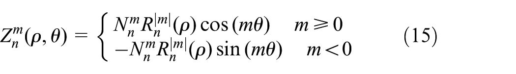
where

where
The B-spline method is expressed by 21

with two knot vectors

where
In the previous studies,1,10,11,19 either polynomial method or B-spline method was used to describe the designed surface, and the specific degree of polynomial or B-spline was given without explanation. With the purpose of guiding the selection of describe method, an evaluation method was proposed to analyze the fitting accuracy of these two methods with different degrees, and the method with smaller fitting error was used as the describe method. Using the methods mentioned above, the values of (N + 1)*(N + 1) grid points on the PAL surface can be calculated. The arrangement of these grid points was as follows. First, selecting (N1 + 1)*(N1 + 1) grid points evenly in the x and y directions, and the values of the selected points in the z direction, which is called as vs, were used as verification data in the subsequent step. Then, the values of the remaining grid points were used to acquire the Zernike polynomials or B-spline equation. According to the Zernike polynomial or B-spline equation obtained above, the values of the selected grid points in the z direction can be calculated. The equation of root mean square error

where M is the number of selected points, and vc is the calculated values in the z direction of the selected points. As a result, the method with smaller fitting error would be used for the description of the PAL surface.
Simulation results and discussion
In this section, some simulation results were presented to verify the performance of the variational-difference method proposed above. In the simulation, the diameter of the surface was 60 mm, the background surface was chosen as a spherical surface with a radius of 137 mm, and the refractive index was n = 1.53. The computational domain for the simulation is chosen as

Partition for the computational domain.
For an ideal PAL, it is important that the values of weight functions in the three main regions are much bigger than that in the remaining four regions. In this work, the weight value is set as 30 in the three main zones and 1 in other regions. Meanwhile, the convolution is used to smooth the discrete data in the different regions. Figure 3 shows the distribution of the weight functions based on the principle mentioned above.

Distribution of the values for weight functions.
Generally, BASE and BASE + ADD represent the optical power of far-view region and near-view region, respectively. This is used to describe the variation of optical power between these two regions. In this study, the related parameters were set as follows: BASE = 3 and 2 diopter, and then the power of near-view region was 5 diopter. Note that a spherical surface was assumed in the simulation, so the mean curvature was negative. The optical power in far-view and near-view zones with a unit of 1 mm could be calculated as follows 19

where

Representation of the distribution of prescribed optical power.
Using the methods mentioned above, the values of 81 × 81 grid points on the PAL surface can be calculated. Following the introduction in section “Description of the surface,” by selecting 21 × 21 grid points evenly in the x and y directions, values of these 441 points in the z direction were used as the verification data. Then, the Zernike polynomial and B-spline equation were obtained by fitting the remaining 6120 grid points. According to the work by Raasch et al., 23 the higher order terms in Zernike polynomial affect the distribution of optical power and astigmatism, so the degree of Zernike should not be too high.
In this study, the degree of Zernike polynomials and B-spline equation was changed from 3 to 7. Besides, only the Zernike polynomials with m = n were used for evaluation. Figure 5 shows the fitting accuracy of Zernike polynomials and B-spline equation with different degrees. As the figure shows, for Zernike polynomials, the fitting error decreases with the increase in the degree in general, and the fitting error of fourth Zernike polynomial is smaller than others. The potential random errors or algorithm defects that appear in the calculation of fitting error may be the cause of this condition. For B-spline equation, when the degree changes from 3 to 7, the fitting errors are almost equal, and smaller than the error of Zernike polynomials with same degree. The reason for the error approximation may be due to the relative small error of each points and the big number of validation points. Besides, the axis scale of fitting error affects the expression of smaller difference. Based on the results, the B-spline equation of degree 3 was used to describe the PAL surface.

Fitting errors of Zernike polynomial and B-spline equation with different degrees.
Figure 6(a) is the background surface w(x, y), which is a spherical surface with a radius of 106 mm. Figure 6(b) shows the addition surface v(x, y) solved by the variational-difference numerical method, which is an exocentric hump structure. Figure 6(c) shows the designed PAL surface fitted by a B-spline equation of degree 3. Note that the shape of the obtained surface is similar to the result in the work by Wang and Santosa, 10 which shows that the numerical results are almost same using these two different methods. Figure 7 shows the optical power distribution and astigmatism of the designed surface. It can be seen from Figure 7(a) that the power distribution of the three main zones on the surface is close to the design values, the designed BASE power of 3 diopter is reached, the power in the near-view zone is about 5 diopter, and the optical power changes smoothly, progressively, and continuously. As shown in Figure 7(b), the astigmatism is nearly zero in the three main zones, and the maximum astigmatism is less than 1.8 diopter.

Presentation of designed PAL surface: (a) background surface, (b) addition surface, and (c) PAL surface.

Distribution of optical power and astigmatism, unit diopter: (a) optical power and (b) astigmatism.
In early studies, the maximum astigmatism was equal to the ADD power. 10 As a result, it is clear that the performance of PAL design with proposed variational-difference method is better. Except the astigmatism, other high-order aberrations also affect the performance of PAL design, 23 and it will be discussed in further study.
Tool path generation for STS turning of PAL surface
There are three steps in the tool path generation for STS turning of PAL surface: cutting contact points planning, tool geometry compensation, and turning trajectory interpolation. Finally, numerical control (NC) program can be generated after the three steps. In the work by Wang et al., 24 these three steps were all studied. According to their study, the equal angle method and the z-direction compensation were more suitable for the discretization of cutting contact points and the compensation of tool nose radius, respectively. Therefore, the equal angle method and the z-direction compensation were used in this study.
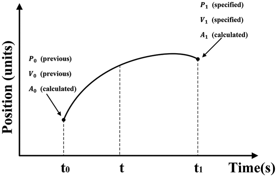
In the process of turning trajectory interpolation, the position–velocity–time (PVT) method is usually used as the interpolation method, and its essence is piecewise cubic Hermite spline interpolation. Figure 8 shows the representation of PVT interpolation. The traditional algorithms for generating the entrance parameters of PVT, such as area method or three-point method, 25 could only ensure that the speed in each cutting tool location point is continuous, but the acceleration at each point is not completely continuous and the interpolation error will increase. So, a new algorithm called triangle rotary method is proposed to overcome the disadvantage, and this method transformed the segment Hermite interpolation into segment spline interpolation resulting in the acquisition of continuous acceleration and smaller interpolation error. As the method shows, the cubic Hermite interpolation polynomial for segment (xi, xi + 1) can be describe as 26

where Sx represents the function value based on x in segment (xi, xi + 1), in which i represents the number of interpolation points; and li represents the derivative of xi and yi in each point.
Schematic diagram of PVT interpolation.
By calculating the two-order derivative on the above equation and assuming the acceleration is continuous which means

Substituting equation (21) into equation (22), the following equation can be obtained

where
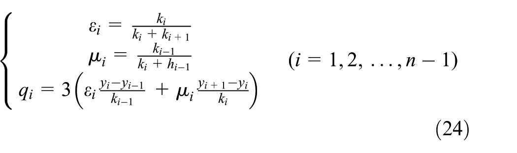
and ki = xi + 1 − xi.
In order to solve the equation, natural boundary conditions are introduced

Finally, equation (23) is transformed into matrix form as follows, and “chasing method” is used to solve equations to get the entrance parameters of PVT method

In order to verify the proposed method and compare the different generation algorithms for entrance parameters, the tool path planning simulation was carried out. The simulated surface is the PAL surface mentioned above with a diameter of 60 mm. The cutting parameters for simulation were selected as C-axis velocity of 100 r/min, feed rate of 1 mm/r, and discretization angle of 10°. Figure 9 shows the interpolation error of different algorithms for generating entrance parameters PVT, and the first 1000 points are analyzed.
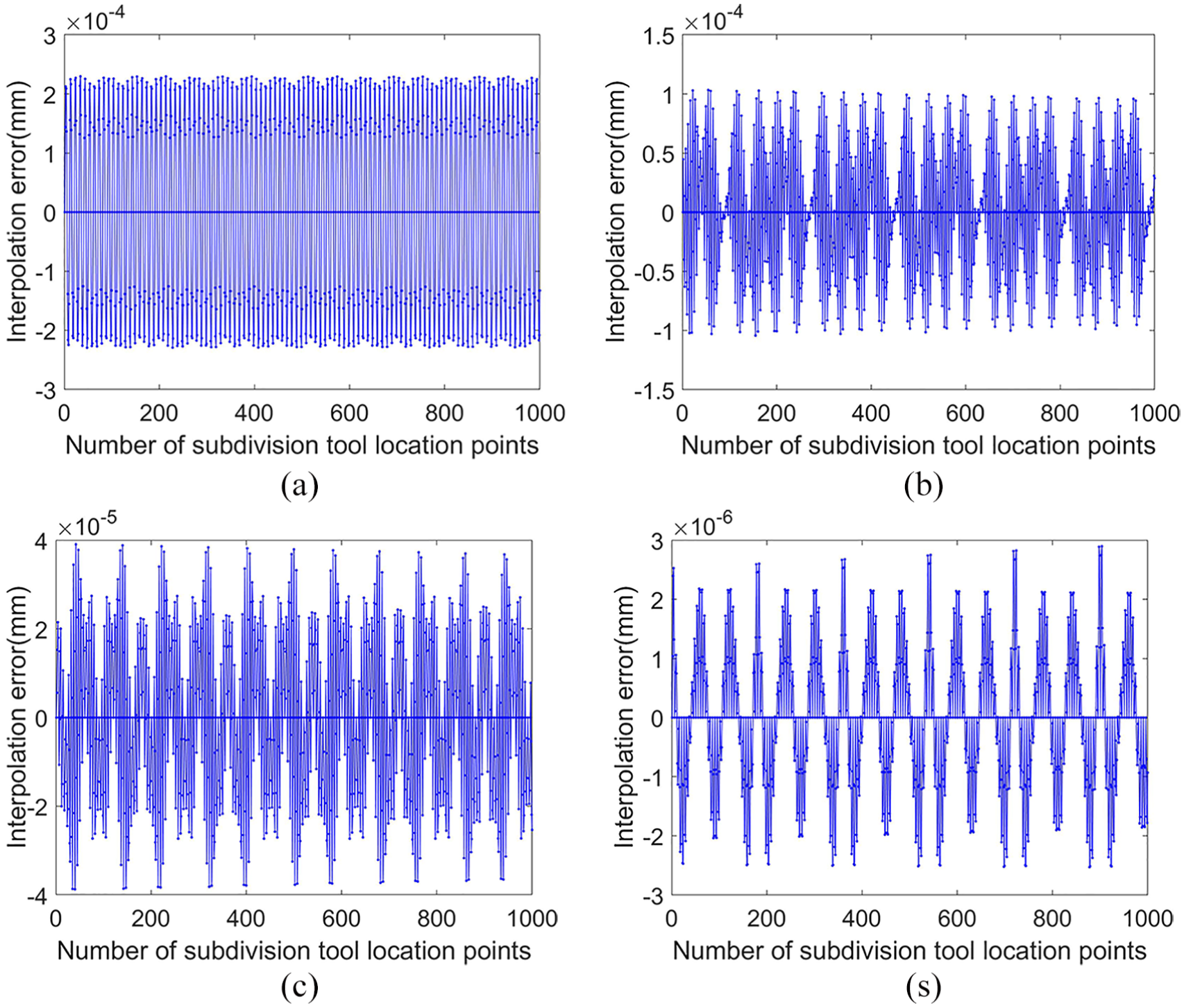
Interpolation errors of the different interpolation methods: (a) area method with c = 1/2, (b) area method with c = 2/3, (c) three-point method, and (d) triangle rotary method.
According to the figure, the maximum interpolation error of area method with c = 1/2 is 0.22 μm, and it becomes 0.11 μm when c = 2/3 (c is the scale coefficient used in area method and
Experimental results and discussion
In order to verify the proposed method, the experiment was carried out on a home-made STS lathe. The schematic diagram of the turning lathe is shown in Figure 10. As the figure shows, both the X-axis and the Z-axis are linear, and they form the T-shaped layout. The C spindle is fixed on the platform moving along X-axis and the tool moving along Z-axis. In the turning process, the workpiece is fixed on the rotary axis, and complex surface can be machined by controlling these three axes simultaneously.

Schematic diagram of STS turning lathe.
The procedure of machining a PAL by STS method contains rough cutting and finish cutting. Then, polishing is used to improve the surface quality. In this work, only the rough cutting was carried out to verify the feasibility of machining method. The front surface of the designed PAL was machined without cutting fluid, and the values of BASE and ADD for the surface were 3 and 2 diopter, respectively. The weight value in the three main zones and the remaining four regions is 30 and 1, respectively. The workpiece is made of resin, and the diameter is 60 mm. The tool is made of polycrystalline diamond, and the tool nose radius is 0.5 mm. The rake angle and clearance angle of the tool are 0° and 10°, respectively. The machining parameters for rough cutting are shown in Table 1. Figure 11 shows the presentation of the designed surface and tool path under the condition mentioned above. In order to make the figure distinct, some points are left out.
Values of parameters used in machining.


Machining PAL surface and tool path.
The surface roughness and form accuracy of the PAL surface machined by area method (c = 1/2 and c = 2/3), three-point method, and triangle rotary method are shown in Figure 12. It can be seen from the figure that the surface quality of PAL surface machined by triangle rotary method is better than that by using other three methods. The experimental results demonstrate that the proposed generation algorithm for entrance parameter can improve machined surface quality.
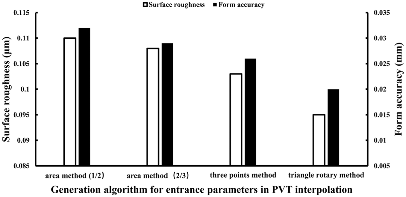
Surface qualities of machined surface with different generation algorithms.
Figure 13(a) shows the workpiece machined by triangle rotary method. Before the measurement, the machined surface was divided into 12 parts by equal angle. Then, a JB-4 C machine was used for the measurement of surface roughness. In each direction, the measurement was conducted three times, and the average results of the 12 directions were used to describe the roughness of the surface. In a single measurement, the cut-off or sampled length was 0.8 mm and the measurement length was 4 mm. The result of one measurement in 0° direction is presented in Figure 13(b). The final surface roughness is 0.095 μm, as shown in Figure 13(c). For the sake of evaluating form accuracy, a MQ686 three-coordinate measuring machine from AEH Corp. was used to measure the surface profile. As shown in Figure 13(d), the PV form error is about 0.02 mm.

Experimental results: (a) machined surface, (b) measurement in 0° direction, (c) average value, and (d) form error (unit: mm).
In the machining of PALs, the requirements for rough cutting are as follows: surface roughness and optical power error should be less than 1 μm and 0.05 diopter, respectively.
27
The optical power error

where hv is the value of PV error and r represents the radius of the surface. The comparison of the requirement and measurement for machined surface is shown in Table 2.
Comparison between requirement and measurement of machined surface.
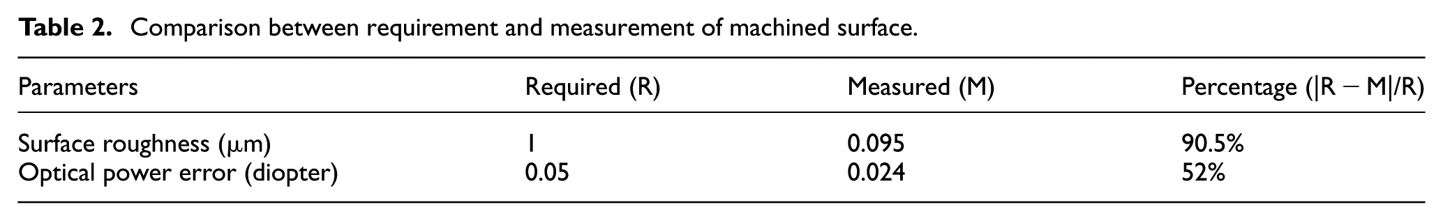
According to Table 2, it is clear that the surface roughness and optical power error of the machined surface are all smaller than the corresponding requirement. The results indicate that the surface quality is satisfactory using the proposed machining method.
Conclusion
This work focused on the design and machining of PALs. The following conclusions were drawn:
The design of PALs was simplified as a functional minimization problem in this work, and the functional was solved by a variational-difference numerical method. Compared with the works using other methods, the variational-difference method solved the problem directly rather than obtaining the approximate solution. The simulation results indicated that the required BASE power and ADD power are reached and the power changes smoothly and progressively using the proposed method. Moreover, the astigmatism in the three main zones was relatively small, and the maximum astigmatism was less than 1.8 diopter, which appeared in the blending zones. Note that also different weighting functions and power distribution functions mean different surface shapes. In the future work, the relationship among them will be discussed.
Although the values of discrete points on the PAL surface can be obtained after solving the functional, it is still necessary to use interpolation or fitting method to construct the mathematical description of the surface. Thus, a method was put forward to evaluate the fitting accuracy of the commonly used Zernike polynomial method and B-spline method with different degrees. The simulation result showed that the fitting error of B-spline method with different degrees is almost equal and smaller than that of Zernike polynomials with same degree. As a result, the PAL surface was described by B-spline method of degree 3.
In the machining of PAL surface, a new algorithm for generating entrance parameters in PVT interpolation of STS turning was proposed. Simulation results showed that this algorithm can reduce interpolation error obviously, and the experimental results demonstrated that the algorithm can be used for the machining of PAL surface. The surface roughness and optical power error of the machined surface are 0.095 μm and 0.024 diopter, respectively, which meet the requirement.
Footnotes
Handling Editor: Xichun Luo
Declaration of conflicting interests
The author(s) declared no potential conflicts of interest with respect to the research, authorship, and/or publication of this article.
Funding
The author(s) disclosed receipt of the following financial support for the research, authorship, and/or publication of this article: The project was supported by the Postgraduate Research and Practice Innovation Program of Jiangsu Province (grant no. KYLX15_0565) and the Natural Science Foundation of Jiangsu Province (grant no. BK20150685).