
Abstract
Most of commercial CAM software solutions (SolidCAM, Unigraphics and etc.) are commonly employed for generating tool paths on machining of freeform surfaces. However, these CAM software solutions are presently unable to support fast tool/slow slide servo diamond turning of freeform surface due to difference in coordinating systems. In contrast to traditional machining processes, fast tool/slow slide servo diamond turning is controlled by both linear and angular positions of the workpiece and is known as polar or cylindrical coordinate system. Hence, a special CAM post-processor is required to generate the spiral tool trajectory in fast tool/slow slide servo diamond turning. However, these special CAM software solutions are very expensive. Manufacturers have been searching for solutions to sustain their competitive advantage in mass producing products at the shortest time to market and at a most economical cost. Hence, these drive the needs for an alternative and economical option of generating accurate tool trajectory for fast tool/slow slide servo diamond turning of freeform surfaces. This article proposes an attractive solution with an integration of Visual Basic application programming interface into SolidWorks to generate spiral tool trajectory for diamond turning of freeform surface. In this proposed methodology, the spiral tool trajectory can be extracted directly from computer-aided design models of freeform surface without utilizing any expensive CAM software. In addition, the critical cutting parameters and tool geometrical angles were also optimized with the developed methodologies for the accurate machining of freeform surfaces in the hybrid fast tool/slow slide servo process.
Keywords
Introduction
Freeform surfaces play the key role in the development of complex optical devices widely used in telecommunication, medical imaging and surveillance systems. Freeform surfaces also allow restriction-free freedom for the optic designers to design products with functional, aesthetic and ergonomic surfaces. Ultraprecision multi-axis freeform machining techniques are often employed for manufacturing freeform surfaces with a high degree of accuracy and precision. Diamond turning, which is one of these machining processes, has the advantages such as high accuracy and high efficiency. Diamond turning is often coupled with unique technique known as fast tool/slow slide servo (FTS/SSS) for manufacturing a freeform surface with a high degree of complexity.1–3 Notwithstanding the fact that FTS system has a high-frequency bandwidth, most of FTS systems have travel limitation and are unsuitable for machining freeform surfaces with sag height greater than 1 mm. Whereas the SSS system has exhibited its capability to fabricate freeform surfaces exceeding 1 mm sag height, and the high-inertia forces from its heavy-weight linear axes slow the acceleration in the movement speeds. Thus, SSS system is not suitable for machining freeform surfaces with higher frequency asymmetries and has lower machining speed as compared with FTS system. These limitations can be overcome by employing a hybrid FTS/SSS method to exploit the merits of FTS and SSS systems.
A hybrid FTS/SSS diamond turning4,5 combines a highly dynamic piezo-driven FTS and an existing machine axis to have several millimetres of stroke at high-frequency bandwidth. Neo et al. 4 have implemented a layer tool trajectory approach to fabricate a prismatic surface with a sag height which was five folds of the FTS stroke length. Brecher et al. 5 have employed a geometrical splitting approach to distinguish the freeform features to be machined by FTS and SSS processes based on the features’ frequency properties. The features with low-order frequency would be done by SSS process and those with high-order frequency would be handled by FTS process. Although the freeform features may be separated by means of geometrical splitting, there were no in-depth details reported for this geometrical splitting approach. Thus, it is still a challenging task to fabricate such complex freeform surfaces using mathematical approaches in the hybrid FTS/SSS process.
It is easier to design the optical freeform surfaces using an application of computer-aided design (CAD) software (SolidWorks, etc.) instead of traditional and tedious mathematical approaches. CAD software offers not only designing solutions but also simulation analysis solutions for both imaging and non-imaging systems. 6 These CAD models could be further utilized for post-processing into tool path by CAM software. However, there are common shortcomings for conventional CAM software solutions which make them unsuitable for generating tool path on freeform surfaces, which are the larger resolution ranges of 10 nm in the CAM systems and lack of post-processing system to support FTS/SSS processes. 7 This large resolution range often causes large shape deviations and poor surface roughness on the fabricated freeform surface. Hence, customized CAM software is deemed necessary for providing suitable post-processor with adequate accuracy in generating tool path of FTS/SSS diamond turning. Gong et al. 8 have successfully developed and implemented the space Archimedean spiral methodology in the UG NX software to generate spiral tool path for FTS/SSS process. However, there is no report of process optimization to machine accurate freeform surface under optimal conditions and the achieved form error was reported to be 2.3 µm. Thus, it is not desired as the requirements for form error should be lesser than 1 µm to have a good optical performance. Although there are available other commercial software solutions such as DIFFSYS 9 and NanoCAM 2D/3D 10 for FTS/SSS diamond turning, they are still very costly. As there is a great intense competition in the market, manufactures have been searching for solutions to sustain their competitive advantage in mass producing products at the shortest time to market and at a most economical cost. Hence, these drive the needs for an alternative and economical option of generating accurate tool trajectory for FTS/SSS diamond turning of freeform surfaces.
Fortunately, the resolution ranges found in most commercial CAD software solutions are finer than those in CAM systems. This advantage could be further exploited for generating tool trajectory on freeform surfaces by employing the Visual Basic application programming interface (API). This built-in API environment has already been found in most commercial CAD software solutions and allows integrating predefined native geometrical entities and operations with any user-defined computational algorithm. This marks the tipping point for growing attention on integration of API and CAD software for reverse engineering methodologies. 11 Thus, it also offers an attractive solution for generating accurate tool path on freeform surfaces other than CAM systems. This article proposes an implementation of computer-aided (CAx)-technologies for FTS/SSS diamond turning of freeform surfaces via an API in the Visual Basic environment. Unlike the conventional CAM software solutions, this methodology not only generates accurate spiral tool trajectory directly from CAD software (SolidWorks) but also optimizes the number of cutting points in the FTS/SSS process.
Hybrid FTS/SSS diamond turning and freeform surfaces
FTS/SSS diamond turning, as shown in Figure 1, is often employed for machining a freeform surface with high degree of complexity. FTS diamond turning integrates a high bandwidth servo unit in an additional W-axis (or superimposed Z-axis) with the existing three axes (X, Z and C) in ultraprecision turning machine. SSS diamond turning is similar to FTS technique except that it employs an existing Z-axis machine table to oscillate the tool at lower bandwidth due to mass inertia caused by heavy-weighted machine axes. Due to the fact that FTS system has a shorter stroke length (⩽1 mm) and SSS system has a lower frequency bandwidth, a hybrid FTS/SSS method is employed to overcome these limitations. It combines a highly dynamic piezo-driven FTS and an existing machine axis to have several millimetres of stroke at high-frequency bandwidth. The tool trajectory in the proposed hybrid FTS/SSS diamond turning still behaves the same as FTS and SSS systems.
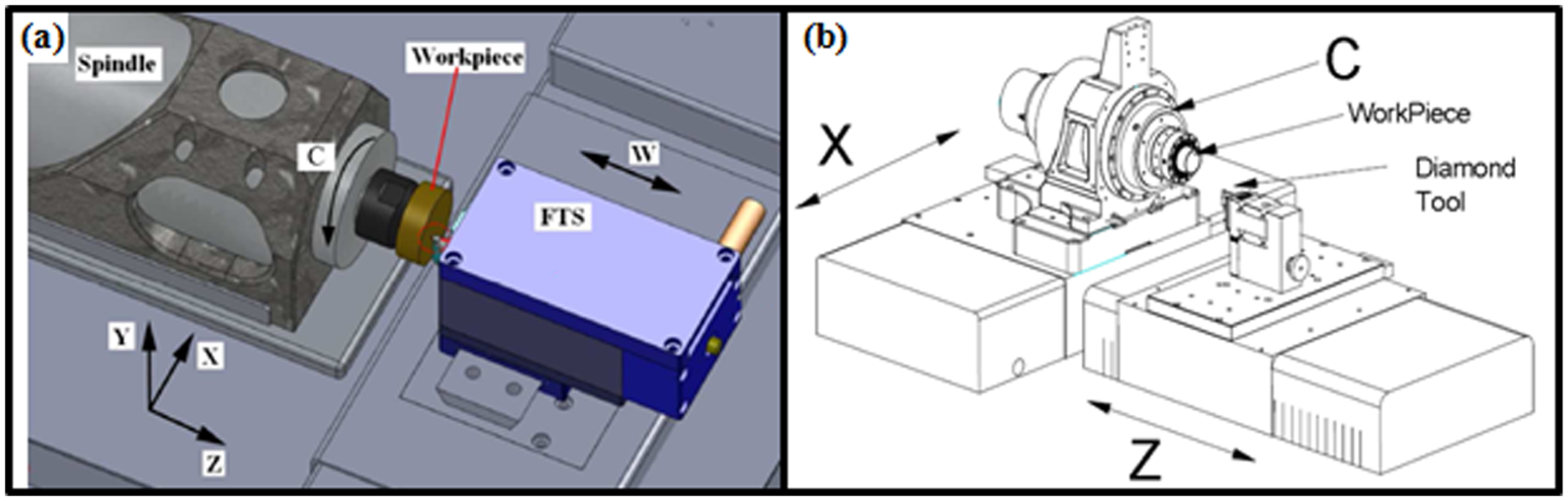
Configurations of ultraprecision lathe machines: (a) fast tool servo and (b) slow slide servo.
In the process of surface generation, the tool trajectory evolves as an Archimedes spiral which usually proceeds from outer radius to the centre of the workpiece. Since the spiral tool trajectory begins at the outer radius r, the radial position of the tool undoubtedly decreases as tool feeds towards the centre. According to Weisstein, 12 the radial position ρ of the tool is given by


where fr is the radial feed per radian, θ is the rotational angle of the machine spindle and θt and Nt are the total angular and the total number of spiral rotations to reach the centre from the outer radius, respectively. Hence, the spiral point P of the tool trajectory in Figure 2 is represented by polar coordinates as


where P contains the coordinates of x, y and z, and both z and W axes are the normal heights from the XY-plane to the point P in SSS and FTS, respectively.
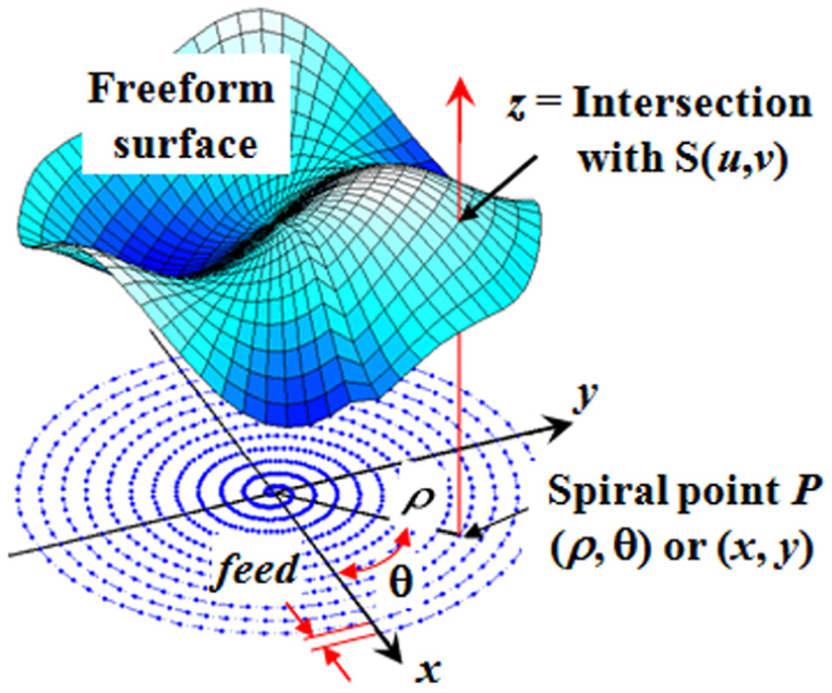
Archimedean spiral tool trajectory in FTS/SSS diamond turning.
Non-uniform rational B-splines freeform surfaces
Freeform surfaces are generally either based on the derived equations or CAD definition. Traditionally, the facetted surfaces with sharp edges and free-forms are defined by the means of section–functional methods. This traditional definition is not only unable to be analytically closed but also difficult to solve numerically. 13 Non-uniform rational B-splines (NURBS) allow a much more elegant and flexible definition of surfaces providing an implicit method of function switching capable of both realizing sharp edges and continuous transitions. Thus, NURBS are a class of splines having ideal characteristics for the specification of machine tool paths. A NURBS-based surface S(u, v) is described in equation (6) and its rational basis functions are weighted pth and qth degree B-Spline basis functions Ni, p with the parameters u and v
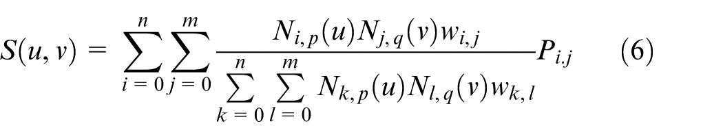
The knot vectors (Ni, p and Nk, p) determine the activation control points on the NURBS surface, while the order of a NURBS surface determines a number of control points influencing any given point on the surface. wi, j and wk, l are the corresponding weight factors. More in-depth knowledge for NURBS-based surface descriptions can be explained in Weck et al., 14 Piegel and Tiller 15 and Brinksmeier et al. 16 It is common knowledge that the conventional machine tool system cannot demystify directly from this description of a freeform surface. Therefore, it is deemed necessary to pre-process the surface data into a tool trajectory with point clouds. In the FTS/SSS diamond turning, the point clouds are given in a spiral point Pi, j in the XY-plane. For the tool path generation, the z-component and the normal vector for every point Pi, j have to be determined for the surface.
It would be tedious and time-consuming process to calculate numerically for both of the intersection point between the line from point P and the surface S(u, v) and the normal vector of the surface. Thanks to the CAD system, the intersection points and the normal vectors could be extracted directly from the NURBS surface data without tedious computations. The details for extracting these intersection points and normal vectors in CAD system are discussed in the next section.
SolidWorks and API
SolidWorks is a one of the widely used commercial software solutions bundled with several packages including API for designing freeform surfaces. API allows implementation of any user-defined algorithm to perform accurate computation by integrating predefined native geometrical entities and operations with a powerful mathematical utility. 11 This mathematical utility feature allows easy performance of basic and advanced points, and vector and matrix operations. Figure 3 describes three groups of objects which can be manipulated with API in SolidWorks, namely, native geometrical, native mathematical and user-defined entities. The native geometrical entities include the sketch entities (point, line, circle, spline, etc.) and their constraints, the features (extrusion, revolution, loft, etc.) and the assembly management (mating, inserting, moving, etc.). The mathematical native entities such as points, vectors and transformations are manipulated for projecting from model space to sketch space and vice versa, performing basic operation on vectors, and so on. Direct accessing into the internal database of entities to execute commands and interlace model entities with math and user-defined entities is also recommended. This would give an optimized handling for extremely large amount of data points.
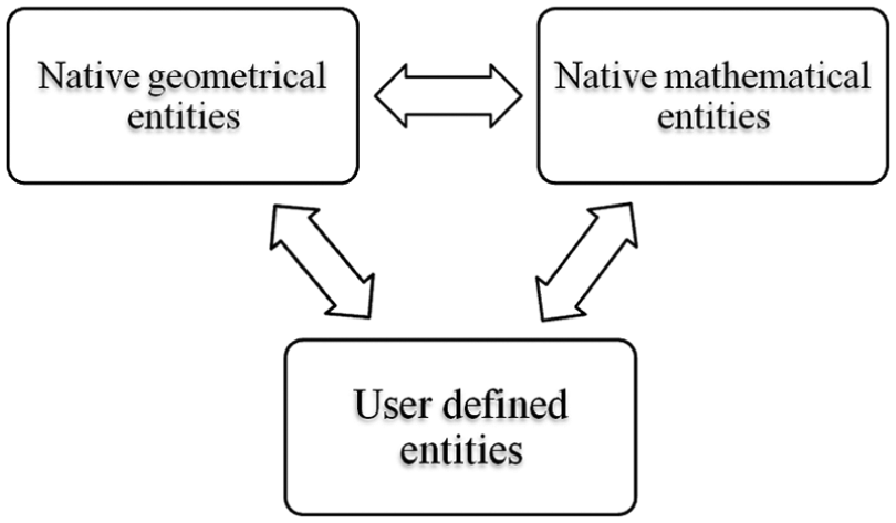
SolidWorks-API entity scheme.
In this study, the process flow, as illustrated in Figure 4, has been implemented to determine the z-values of the intersection point on the NURBS surface. First, the mathematical utility performs point operations to create points and vectors in the CAD database with respect to the spiral points P using the existing built-in API functions, namely, ‘CreatePoint’ and ‘CreateVector’. However, a NURBS surface in a CAD model usually contains several faces which are necessary to be geometrically defined using built-in geometrical entity API function ‘GetFaces’. This ‘GetFaces’ function identifies those faces associated to a NURBS surface. Then, the evaluated normal vector intersects onto a selected face of NURBS surface by employing a geometrical entity function ‘GetProjectedPointOn’. Since these faces are randomly selected and may not have a resulted projected point, it is necessary to perform iteration to select the next ‘face’ until a resulted projected point is obtained. Finally, the resulted projected point is also known as one of the cloud points on NURBS surface, which can be further processed into a tool trajectory control point. This cycle shall be repeated until it reaches the end of the spiral trajectory. Furthermore, this proposed API approach is also employed for computing the cutting linearization errors for optimizing the hybrid FTS/SSS process. The details of the cutting linearization error are explained in section ‘CAx-technologies for hybrid FTS/SSS process’.

Process flow for computing z-value of intersection point on NURBS surface.
CAx-technologies for hybrid FTS/SSS process
The primary objective of the CAx-technologies is to construct the software tools for planning and conducting the manufacture of freeform surface within the hybrid FTS/SSS process and to make available open interfaces for the different adaption technologies. The computer-aided engineering (CAE) technology cluster, which is one of the core clusters in the CAx, consists of three sub-clusters, namely, cutting methodologies, geometry splitting of freeform features and optimization of tool geometry.
Cutting methodologies
Surface generation is no longer just a tool path generation, but also a necessity tool for optimizing the profile accuracy and the process. Hence, two approaches, namely, hybrid constant-angle and constant-arc (HCAA) and cutting linearization error (peak-to-valley error (PVerr)), are developed and implemented in the cutting methodologies and are discussed in the following sections.
HCAA method
Two cutting strategies, namely, constant-angle and constant-arc, are commonly employed in the FTS/SSS process. The constant-angle method generates the control points in a manner where the number of control points for every revolution, that is, Δθ, is constant. However, constant-arc method gives a constant arc length ΔS between two corresponding points throughout the entire surface. Zhou et al. 17 reported that the surface quality of outer regions is worse than that of central regions when the constant-angle method is employed. When the constant-arc method was employed, the surface quality of machined surface was uniform. This was due to arc lengths between the corresponding points on outer regions that are sparser than those on central regions. However, Neo at al. 18 reported that there was a ‘sprue-shape’ contour error PVerr found in the central region under the constant-arc method. This can be explained by the fact that the arc length S is a function of θ and the associated angles are larger near the centre of the part than in outer regions. It is also revealed that the PVerr results in the outer regions were much lower than the required contour tolerance PVtol when the ΔS was shortened to reduce this ‘sprue-shape’PVerr. Thus, an HCAA method has been employed for overcoming this ‘sprue-shape’PVerr problem.
In the HCAA method, as illustrated in Figure 5, the constant-arc method generates the cutting points from the outermost radius of the surface until a point where a transition radius is. Then, the constant-angle method is applied from the point where the constant-arc method is abandoned. This transition radius rtrans locates at a radial location where the PVerr exceeds the required PVtol. Both PVerr and rtrans can be determined by means of the analysis of cutting linearization error in the cutting direction. The details of this cutting linearization error are explained in the next section.
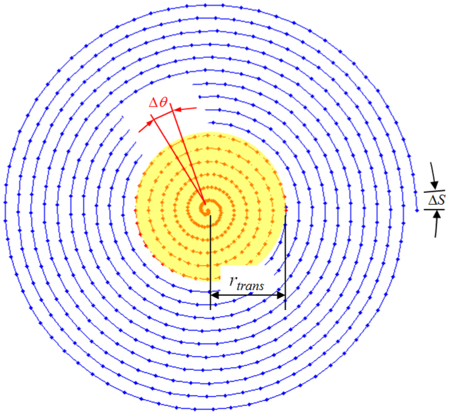
HCAA method of controlling tool trajectory.
Cutting linearization error
Presently, the machined freeform surface is often evaluated after the machining stage in the traditional FTS/SSS process. This gives a high risk of having a machined surface failing to meet the profile accuracy requirements as the cutting linearization error has never been taken into account. Hence, the cutting linearization has to be taken into account for generating accurate tool trajectory. Cutting linearization error is the PVerr between the ideal surface profile and the linear tool trajectory in the spiral cutting direction. The arc length S is the length of the arc from the centre of the workpiece to a cutting point P and is given as 18
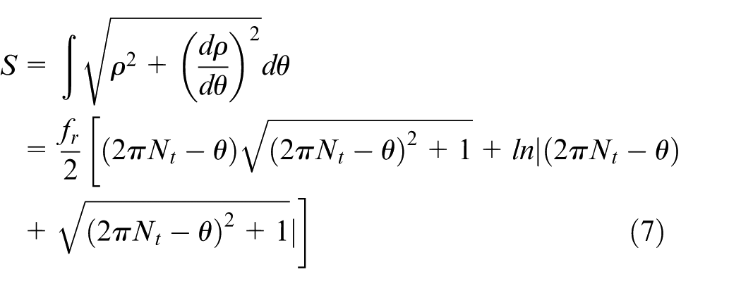
In the following, PVerr will be evaluated to optimize the FTS/SSS diamond turning process and ensures that the tool trajectory in the cutting direction lies within the profile tolerance zone. As explained in Figure 6, a local PVerr (δerr) can be determined by identifying a maximum deviation ∂Zmax between two corresponding cutting points. ∂Zmax represents the critical point on the ideal curve. δerr is given as
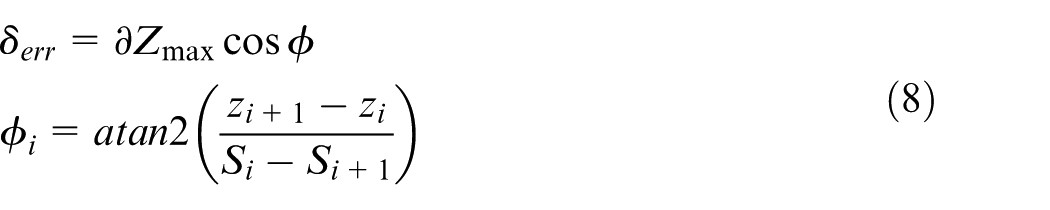
where ϕi is the slope of tool trajectory and atan2 is a four-quadrant inverse-tangent function whose range is (−π, π).
Schematic diagrams for (a) tool path and ideal surface curves, (b) maximum height difference and (c) δerr.
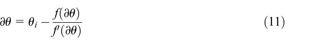
Newton’s iteration method is employed to evaluate ∂θ with known ∂S for determining the maximum deviation ∂Zmax. From equation (8), the corresponding arc length 18 is
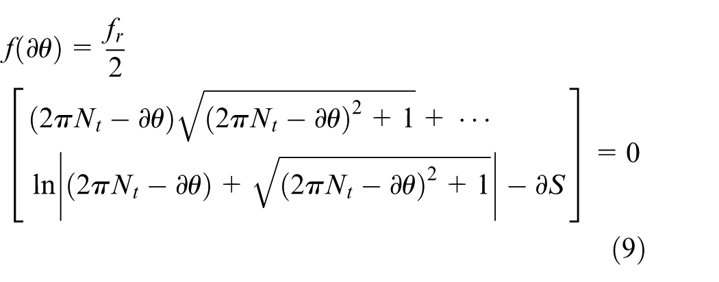
Then, its derivative is
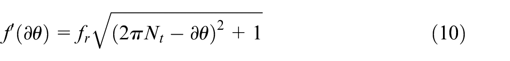
The iteration is continued until convergence has been obtained (i.e. ∂θj − ∂θj + 1 ⩽ 10−9)
From equation (1), the radial position ∂ρ corresponding to ∂θ can be found as

From equation (6), the ideal surface heights between two control points are

The actual heights of the tool trajectory are
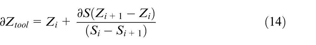
Finally, ∂Zmax is the maximum deviation between ideal surface height and actual height of the tool trajectory

The entire procedure must be repeated for all corresponding control points to evaluate PVerr. The details of establishing the critical machining parameters are explained with the case studies in section ‘Experimental validation’.
Hybrid Hilbert transform/fast Fourier transform methodology for geometry splitting of freeform surface
Generally, a freeform surface has a sag height (>1 mm) and may also come in the form of hybrid surfaces. It is only possible to machine such surface by a diamond turning process with a hybrid FTS/SSS technology having a large stroke length and high-frequency bandwidth. Thus, this freeform surface requires proper segregation of freeform features in order to be fabricated by FTS and SSS processes. In this study, fast Fourier transform (FFT) and Hilbert transform (HT) approaches are implemented to split these freeform geometrically based on their frequency properties.
FFT is a powerful mathematical tool that allows the generated tool trajectories to be viewed in a different domain, where several distinguished properties have been simplified for detailed analysis. 19 In this FFT approach, the (forward, one-dimensional) discrete Fourier transform of the generated tool trajectory signals, dZ, is given by
where ∂z is the incremental change for z-height of tool trajectories. However, a real cutting trajectory for a freeform surface contains multiple frequencies and it is very difficult to analyse using the FFT approach. This multiple frequency issues can be overcome by HT approach.
HT has been recognized as a very important method in different branches of science and technology, from complex analysis and optics to circuit theory and control science.20,21 Their sampled derivations have been encountered in different applications from applied science and engineering. The HT behaves like a FFT and is a linear operator. It is also useful for analysing non-stationary signals by expressing frequency as a rate of change in phase, so that the frequency can vary with time. The HT is often introduced as a convolution between f(x) and −1/(πx) 22
If x(n) is a causal and absolutely summable real sequence with a discrete time Fourier transform X(ejω), then HT can rewritten as 23
where Xre(ejω) and Xim(ejω) are the real and imaginary parts of X(ejω), respectively. The details of establishing the geometrical splitting of freeform feature based on frequency properties are discussed in section ‘Experimental validation’.
Optimization of tool geometry
It is commonly known that the tool geometry has to be optimized not only for machining workpiece material effectively but also avoiding interferences by both the tool rake and flank surfaces onto the workpiece. In contrast to the conventional diamond turning process, the curvatures of NURBS surface are also influencing factors that should be considered for designing diamond tool rake angle (γ), clearance angle (α) and included angle (β). Few researchers24,25 have developed mathematical models to optimize the tool geometry for FTS diamond turning process. However, their models are only considering the two-dimensional surface profiles along the radial and cutting directions, which may not be as distinguished as three-dimensional (3D) surface profiles in a CAD system. In this section, the methodologies for extracting the critical tool geometrical angles directly from CAD model of freeform surface within the SolidWorks designing environment have been proposed.
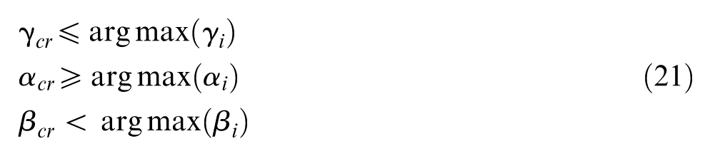
First, the cutting interference between tool rake face and the surface contour could occur only when the rake angle γtool is negative, as shown in Figure 7(a). Thus, tool rake angle should not exceed the critical rake angle γcr which is the maximum negative rake angle before the tool rake face meets the surface along the cutting direction. Second, the cutting interference between tool flank faces and the surface occurs at the downhill of contour when the front clearance angle is insufficient, as shown in Figure 7(a). Hence, the front clearance angle αtool should be greater than the critical value αcr for the flank faces to be free from contacting the surface contour along the cutting direction. Finally, the tool-included angle is also important and necessary for avoiding unnecessary overcutting on NURBS contour along the radial direction, as illustrated in Figure 7(b). The tool-included angle βtool should be less than the critical-included angle βcr in which the tool cutting edge does not overcut the surface contour.
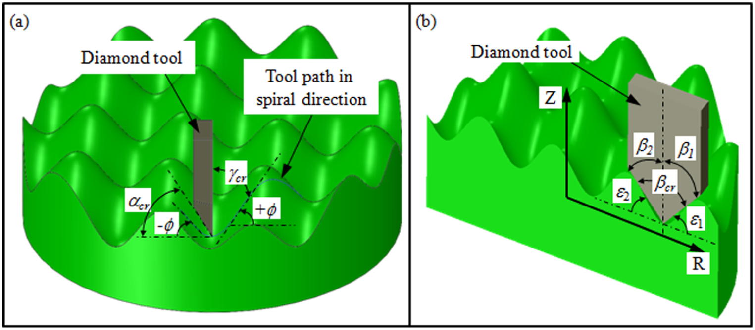
Defining critical tool geometrical angles: (a) rake and front clearance and (b) included angles.
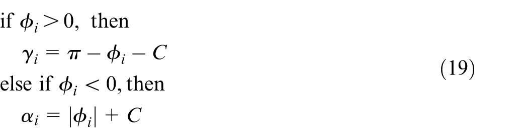
Both γ and α angles can be determined from the slopes of the surface contour ϕ along the cutting direction and defined as
However, β is defined as
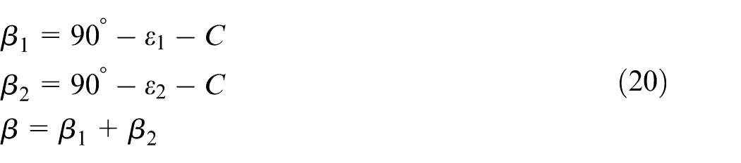
where ε is the slope of the surface contour along the feed direction and C is the clearance angle for preventing tool faces to meet the surface. Thus, their critical values are as follows
In the final stage, there is also another factor to be considering for designing these critical angles, especially the front clearance angle, which is the immediate availability of standard tool sizes in the commercial market. Usually, a diamond tool is tailor-made according to the critical tool geometrical angles. However, it would be extremely costly and takes a long duration of time for manufacturing customized diamond tool. On top of that the maximum front clearance angle for diamond tool design is up to 30° depending on the manufacturers. Hence, these drive the needs for alternative solution of designing diamond tool geometry at shortest time and economical cost. In this section, another way to increase the clearance angle can be done by titling the tool holder away from the workpiece as illustrated in Figure 8. Thanks to the tilted angle λ, the effective front clearance angle αeff and effective rake angle γeff also change. Hence, the maximum tilted angle λmax can be determined by

where γtool and αtool are the actual geometrical angles of a standard diamond tool. The details of determining the critical tool geometrical angles are elaborated with case studies in the next section.
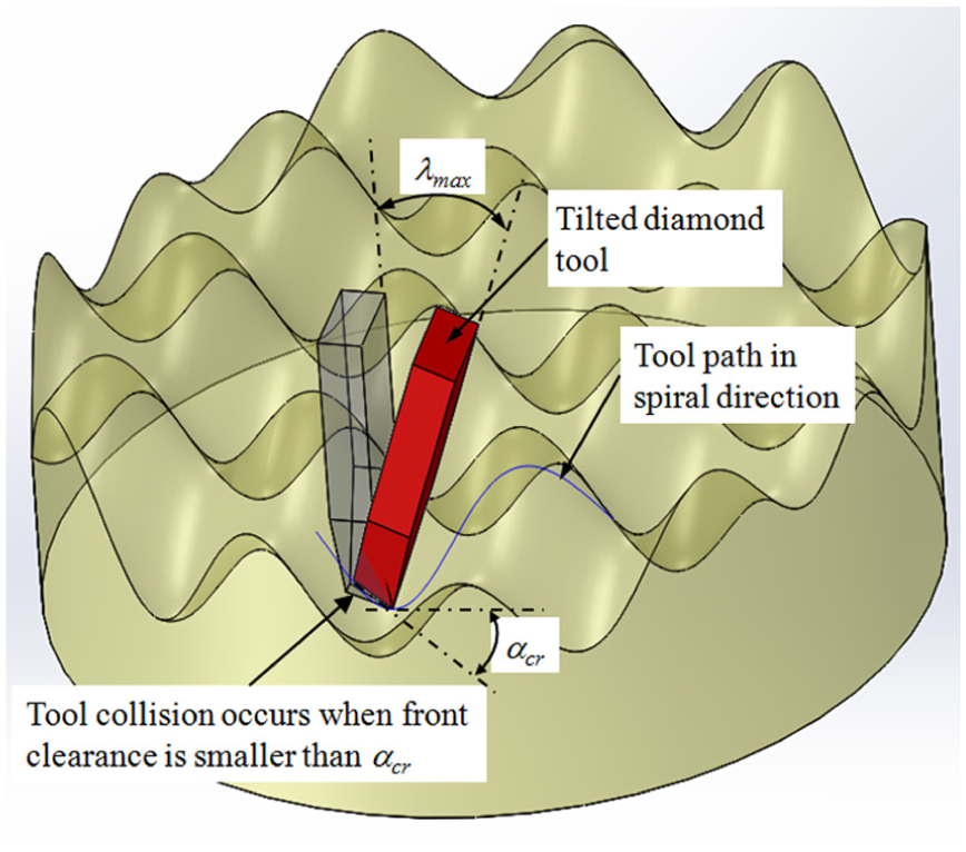
Schematic diagram of titling tool holder.
Experimental validation
The proposed methodologies were implemented into the SolidWorks CAD system using its Visual Basic 6.0 API environment to verify their capabilities to generate accurate spiral tool trajectories. Figure 9 shows the screenshot image of the user interface in the developed SolidWorks-API system.
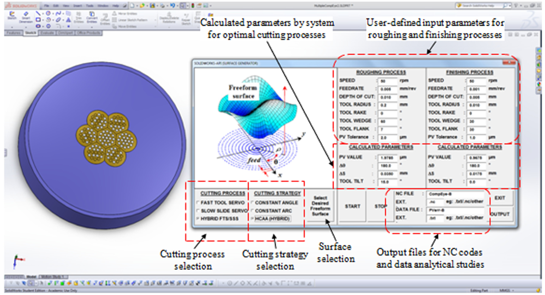
Screenshot image for the user interface of the developed SolidWorks API to generate the spiral tool trajectory for hybrid FTS/SSS process.
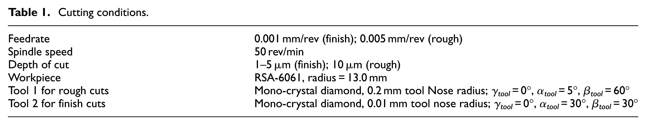
In the experiments, a hybrid FTS/SSS diamond turning technique is employed with an ultraprecision lathe to fabricate a multiple-compound eye surface, as illustrated in Figure 10. This surface consists of seven single-compound eye elements arranged in a hexagonal layout on the largest spherical surface. Each element also contains 17 lenses arranged in a hexagonal layout on the smaller spherical surface. The parameters as described in Table 1 are also selected for the cutting conditions in the experiments. The workpiece material used for the cutting experiments is a modified grade of aluminium alloy AA-6061, known as rapidly solidified alloy RSA-6061. In contrast to traditional AA-6061, RSA-6061 has demonstrated a good performance with nanometric surface finishing using the diamond turning process when employed for making optical inserts. This is because it has fine microstructures that result in highly improved mechanical and physical properties due to the superfast solidification in the melt-spinning process.26,27
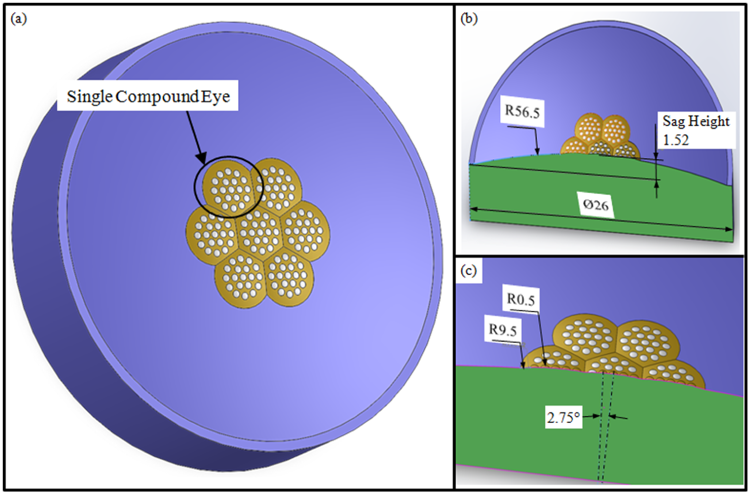
Multiple-compound eye design: (a) 3D view, (b) sectional view and (c) enlarged view of (b).
Cutting conditions.
Before the cutting experiments, it is deemed necessary to pre-determine the critical cutting parameters (constant angle Δθ, constant arc length ΔS and transition radius rtrans) and critical tool geometrical angles (γcr, αcr and βcr) for accurate freeform surface with free of tool interferences. Hence, the cutting parameters, as in Table 1, were input into the developed user interface, as shown in Figure 11. With these inputs, the critical machining parameters and critical tool geometries are evaluated by the integrated system. The analytical details of critical parameters are obtained from the output data files and presented in the next sections.
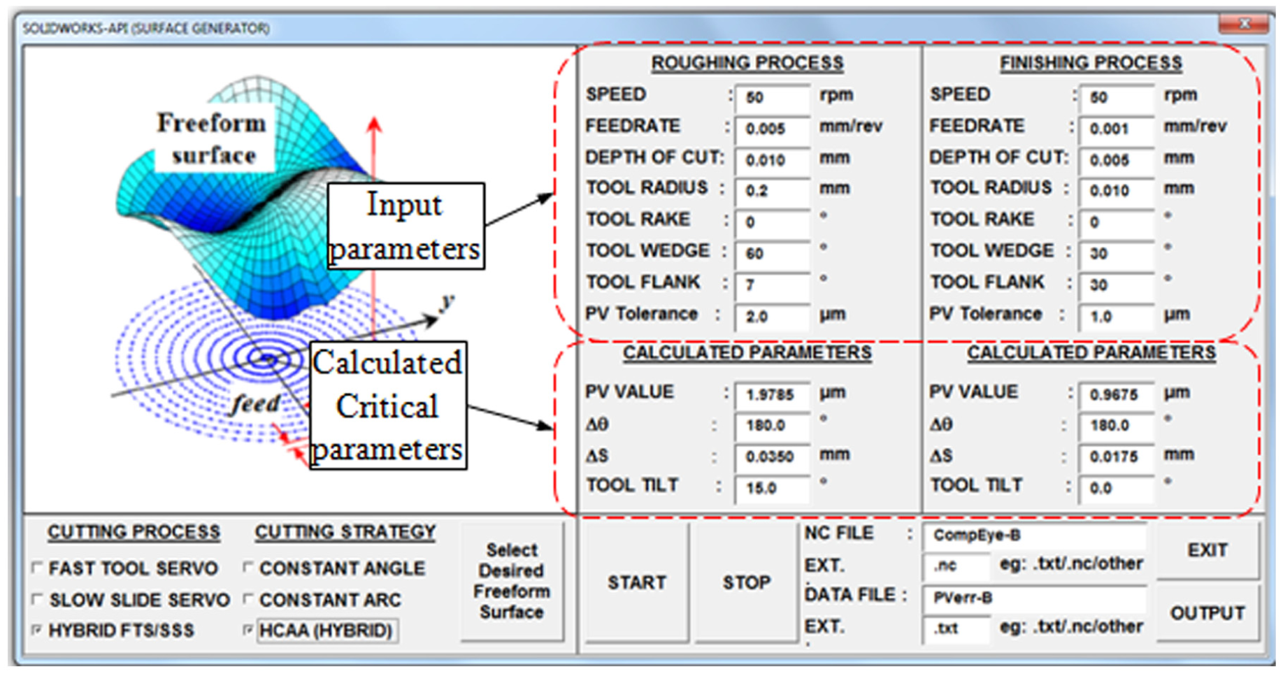
Screenshot image for the calculated critical parameters by the developed SolidWorks-API system.
Evaluation of critical machining parameters for HCAA method
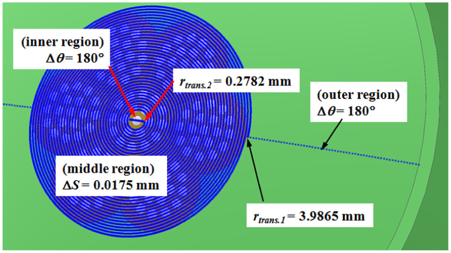
It is common knowledge that more control points yield a better profile accuracy. However, the maximum frequency of control point sequence should not be greater than the bandwidth of FTS/SSS system. Thus, a trade-off is necessary for achieving accurate profile with optimum number of control points. Figure 12 illustrates the calculated PVerr of the desired freeform surface for HCAA cutting strategy, which were replicated using MATLAB software. From Figure 12(a), the critical value of ΔS in the middle region should not exceed 0.0175 mm for meeting the required PVtol of 1 µm using the constant-arc cutting strategy, and the evaluated PVerr value was 0.9675 µm. The critical value of ΔS should not exceed 0.0350 mm for meeting the required PVtol of 2.0 µm in the roughing cuts, and the evaluated PVerr value was 1.9785 µm. However, both outer and inner regions have the least PVerr values (∼0) which make them suitable for constant-angle cutting strategy, as illustrated in Figure 12(a) and (b), respectively. Then, these two regions are re-evaluated for the PVerr under constant-angle conditions. Due to the fact that there is no change in the surface curvatures in these regions, the critical values of Δθ parameters are only 180° (at least two control points) in order to meet the required PVtol.
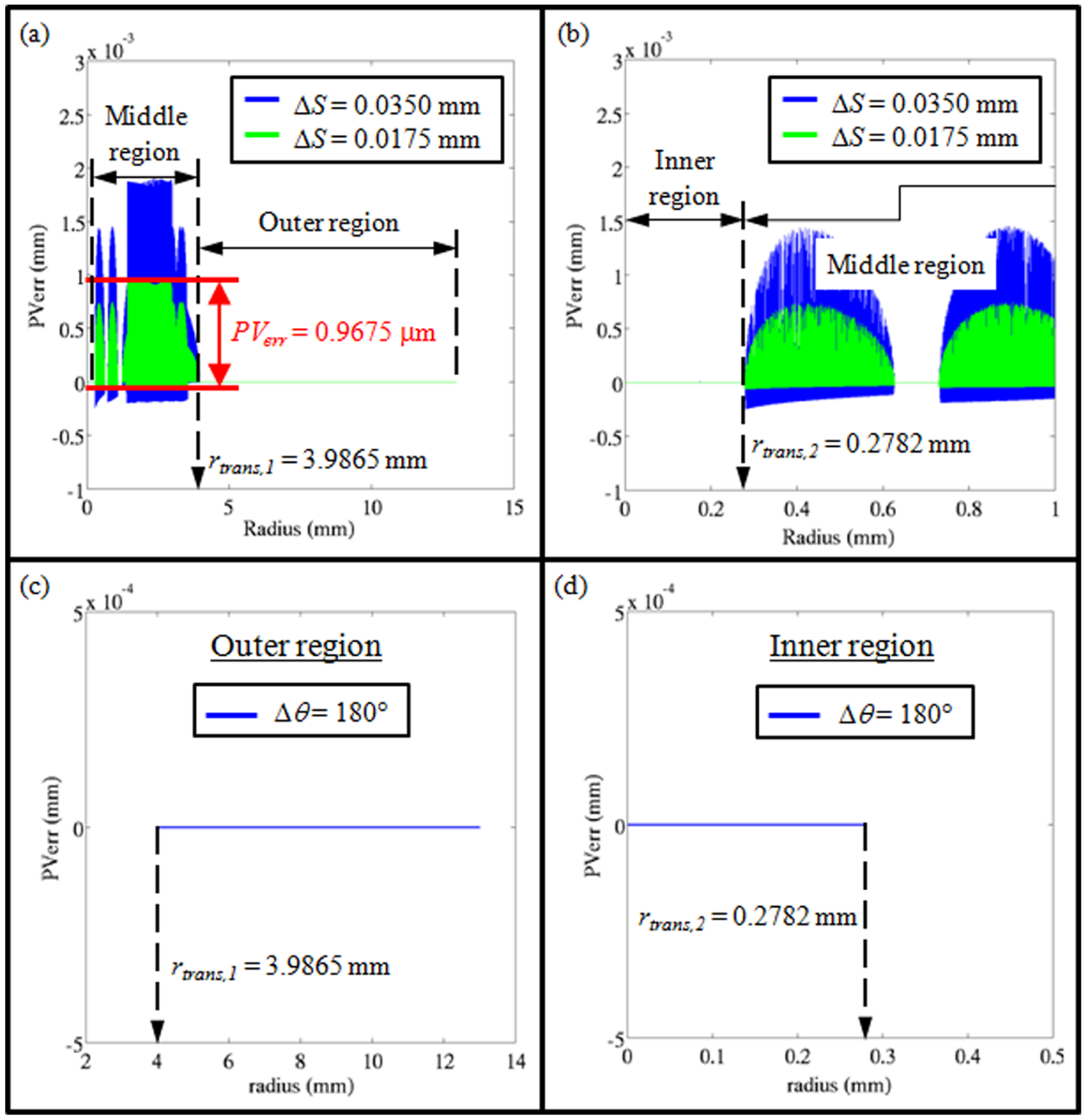
Evaluation of critical parameters for achieving PVtol of 1 µm in HCAA cutting strategy. It shows that there are two possible transition radiuses (rtrans1 and rtrans2) located at (a) 3.9865 mm and (b) 0.2782 mm, respectively. The critical ΔS is 0.0175 mm for middle region and the critical Δθ is 180° for both outer and inner regions.
Thus, the cutting strategy would begin as a constant-angle method from the outer region until the spiral tool trajectory reached the first transition radius (rtrans1) of 3.9865 mm. Then, the cutting strategy would switch to a constant-arc method for the inner region. When the tool trajectory reached the next transition radius (rtrans2) of 0.2782 mm, the cutting strategy would revert to the constant-angle method for the inner region. With the implementation of this HCAA cutting strategy, the number of cutting points for the finishing process was found to be reduced tremendously by 90.6% (from 303,388,091 to 28,409,223 cutting points). This would help to reduce not only the machining time due to lesser times for acceleration and deceleration between the corresponding tool trajectory points but also the file storage size for numerical control (NC) codes.
Evaluation of geometrical splitting for hybrid FTS/SSS process
The generated tool trajectories for freeform surface have multiple frequencies, as explained earlier in section ‘Hybrid Hilbert transform/fast Fourier transform methodology for geometry splitting of freeform surface’, and can be easily simplified for geometrical splitting by means of HT and FFT. Figure 13 demonstrates that the desired freeform surface has two distinguished frequencies at 6.098 and 47.03 Hz. These frequencies can be represented as the degrees of curvature in the freeform features. Thus, the freeform features are able to split into two freeform surfaces, as illustrated in Figure 13(b) and (c). These two freeform surfaces are further validated with HT and FFT approaches and have proven that their frequency properties are very close to those of the original surface. Hence, the features with low-order frequency can be realized by SSS process and the others with high-order frequency to be handled by FTS process.
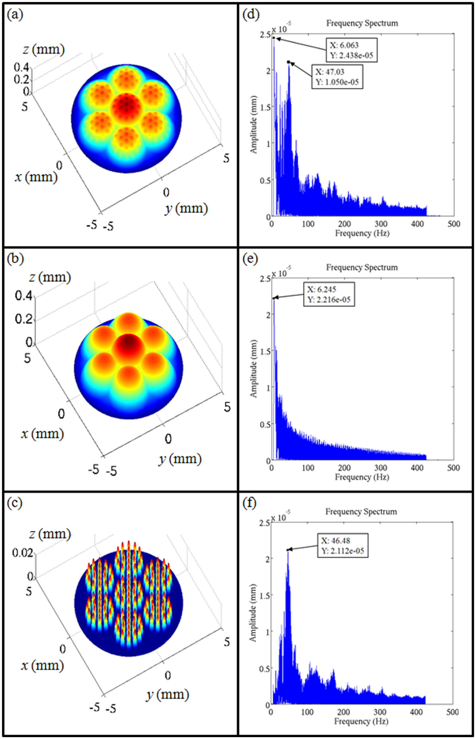
Geometry splitting for hybrid FTS/SSS process: (a–c) 3D profiles and (d–f) calculated frequency spectrums for the original, low-order (SSS) and high-order (FTS) surfaces, respectively.
Evaluation of critical tool geometrical angles
It is necessary to avoid any tool interferences during the cutting of freeform surface. Figure 14 shows that the critical values for tool rake γcr and front clearance αcr angles are about 70° and 20°, respectively, and the critical half-included angles (βcr1 and βcr2) are about 65° and 70° respectively. From the results, it can be concluded that Tool 2 is safe from tool interference onto the machined surface since its tool angles have met the requirements of the critical values. However, there will be tool interference for Tool 1 as its front clearance angle (5°) is lesser than the critical value. Thus, a tilted angle is necessary for Tool 1 which is about 15° in order to meet the requirements of avoiding tool interferences by both the tool front and the rake faces.
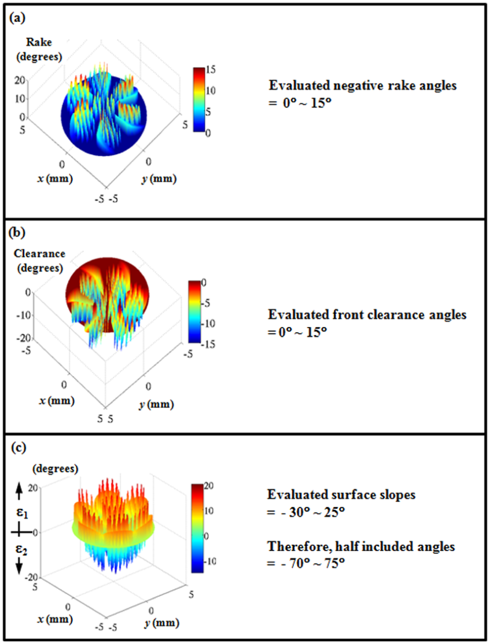
Evaluation of critical tool geometrical angles for C = 5°.
Cutting experiments and results
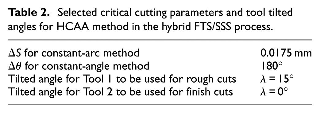
All the experiments were conducted by a hybrid FTS/SSS process using HCAA method. Based on the simulated results from the above methodologies, the machining parameters (Table 2) were selected in machining a multiple-compound eye surface to meet the required PV tolerance of 1.0 µm. Figure 15 exhibits a successful generation of spiral tool trajectory points for the HCAA cutting strategy, which were mapped onto the surface of the CAD model with the implementation of the developed SolidWorks-API methodologies. These generated spiral points were further post-processed into NC code and employed in the machining of multiple-compound eye surface using the hybrid FTS/SSS process.
Selected critical cutting parameters and tool tilted angles for HCAA method in the hybrid FTS/SSS process.
Successful generation of spiral tool trajectories for HCAA cutting strategy, which are mapped onto the surface of the CAD model.
Figure 16 demonstrates that the proposed methodologies have been experimentally validated with the successful machining of multiple-compound eye surface. The machined surface was measured using a measuring laser microscope with a confocal optical system that only captures the in-focus image and eliminates the flare simultaneously. 3D measured profile data were further post-processed using MATLAB software for surface characterization.
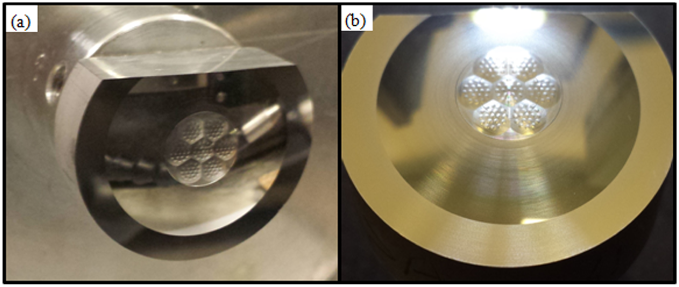
Photographic images of fabricated multiple-compound eye surface: (a) fabricated workpiece mounted on a chuck and (b) top slanted view.
Figures 17(a) and 18(a) illustrate the replication of 3D contour measurements for the central and offset compound eye surfaces, respectively. Figures 17(b), (c), 18(b) and (c) show that the measured contour errors in the selected regions of the central and offset compound eye surfaces, respectively, were found to be lesser than the targeted PVtol of 1.0 µm. Hence, these results validate the proper selection of critical cutting parameters, ΔS and Δθ, for the machining of the freeform surface using HCAA cutting strategy.
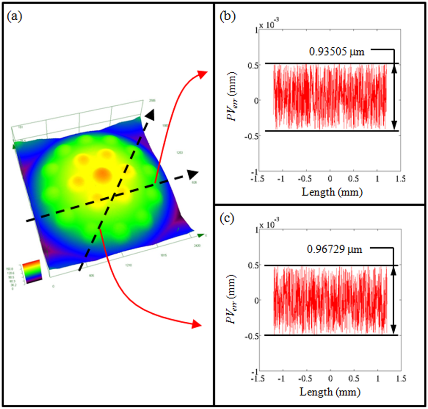
Contour error measurements of central-compound eye surface: (a) 3D contour and (b-c) contour errors in the selected regions.
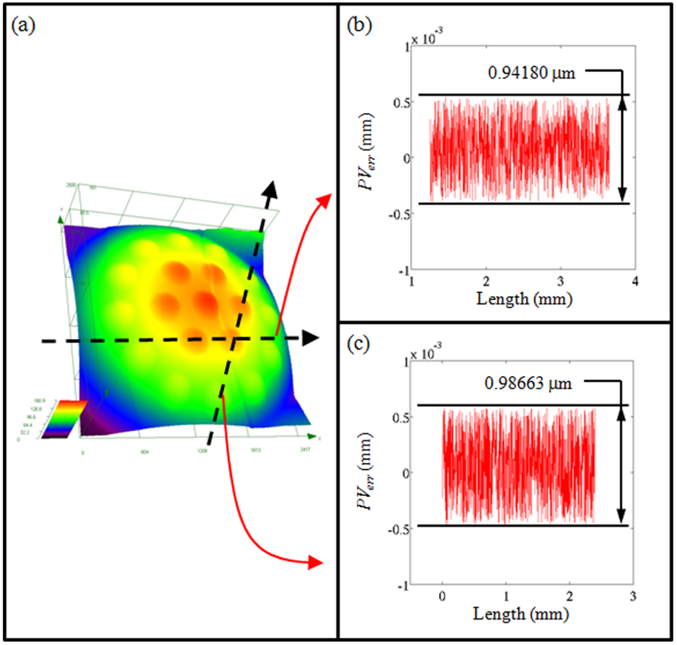
Contour error measurements of corner-compound eye surface: (a) 3D contour and (b-c) contour errors in the selected regions.
In addition, no tool interference/rubbing marks are detected on the machined surface. Furthermore, the hybrid freeform surface with large sag height (>1 mm) and multiple freeform features has been successfully machined with the hybrid FTS/SSS process. Therefore, these experimental results have validated the credibility of the proposed methodologies, hybrid HT and FFT, and tool geometrical optimization for incorporating into the integrated SolidWorks-API system to fabricate hybrid freeform surface accurately.
Conclusion
In this study, the CAx-technologies for accurate CAD/CAM interpolator have been developed to fabricate complex freeform surface using hybrid FTS/SSS process. The proposed methodologies not only replace the needs of expensive specialized CAM software but also provide an attractive solution with an integration of Visual Basic API into SolidWorks for accurate and optimized surface generation of freeform surfaces.
The profile accuracy requirements for the freeform surface have been met. The contour evaluation has demonstrated that the PV errors (PVerr) were within the specified tolerances. Moreover, the hybrid approach of HT and FFT performs a proper segregation of freeform features in order to be fabricated by FTS and SSS processes separately. In addition, the tool interference/rubbing marks are also eliminated with an aid of tool geometrical optimization approach. This provides an essential contribution towards the improvement of CAD/CAM supports for ultraprecision machining of complex freeform surfaces.
Footnotes
Declaration of Conflicting Interests
The author(s) declared no potential conflicts of interest with respect to the research, authorship and/or publication of this article.
Funding
The author(s) received no financial support for the research, authorship and/or publication of this article.