
Abstract
This article presents an innovative approach to toolpath generation for ultraprecision machining of freeform optic surfaces based on the principle of Automatic Dynamics Analysis of Mechanical Systems. As components with freeform surfaces often have non-rotational symmetry, there are potential challenges facing their ultraprecision machining through single-point diamond turning, such as the projected points in complex large sag surfaces, which likely find it difficult to communicate with the control system and, thus, do not perform successfully. In ultraprecision machining, to achieve the highest performance in freeform surface resolution, the factors of dynamics, material and mechanical stiffness, frictions, tooling and accuracy of the servo component should be considered. The investigation is focused on an integrated approach and the associated scientific understanding of precision engineering design, ultraprecision machining and metrology of freeform surfaces as well as their application perspective. In this approach, the toolpath for very complex freeform surfaces can be generated using the Newton–Raphson method to solve the kinematics and dynamics equations of motion. The effect of friction and contact force are also investigated for accurate toolpath curve generation. Moreover, the Gear stiff (GSTIFF)/ Wielenga stiff (WSTIFF) integrator for solving the non-linear equations of motion is employed, and the result shows the time step size, playing a critical role in generating toolpath curves with a higher accuracy and resolution.
Keywords
Introduction
Freeform optics can remarkably intensify a system with complex optical feature requirements and deliver integration and simplification of complex engineering systems. They have, thus, been increasingly employed in the precision engineering industries, including automotive, defence, aerospace and medical engineering. 1 Ultraprecision machining of freeform optic surfaces through diamond turning is becoming the most reliable and trustworthy enabling process, as it can employ high accuracy and efficiency by integrating with the distinctive techniques known as Fast Tool Servo (FTS) and Slow Tool Servo (STS). The integration of these techniques renders the robust capability of ultraprecision machining of complex surfaces such as polynomial freeform, aspheric cylinders, Non-Uniform Rational B-Splines (NURBS)-defined freeform surfaces, lens arrays and bi-conic lenses. According to the process chain, it initially employs computer-aided design/manufacturing, three dimensional (3D) CAD/CAM, software to generate the toolpath trajectory, and then, the compensation of surface form error is deployed to modify and correct the tool trajectory.2–4 For multi-axis machining of freeform surfaces, toolpath generation (TPG) methods have been studied and developed extensively by the academic and industrial communities.5,6 Whilst the STS technique provides a longer stroke, often at a millimetre level, it has a limitation in its bandwidth, thus constricting the speed of the C-axis (in the tool trajectory) in machining complex freeform optic surfaces. Hence, to achieve very high resolution and accuracy, FTS is often used for freeform surfaces ultraprecision machining.7,8
There are potential challenges towards ultraprecision machining of non-rotational symmetry (NRS) surfaces through diamond turning. 9 During the machining process, the diamond tool has to move as a function of the spindle rotation and translation of the machine slide. The methodology above is different from using tool servos separately to generate the tool motion. Fang et al. 10 studied, systematically, cylindrical coordinate machining (CCM) for freeform optic surfaces, which were constructed with feature points fitted to typical NURBS. In their study, all the designed points have the mapping coordinates in the variable space with the inversion technique, while the other NURBS points have their coordinates through the interpolation technique. The derivation and mathematical features are obtained using the fitting formula. Cheng 11 studied an approach to machining micro-structure surfaces with the controller configuration, integrating the FTS with the diamond turning process. In the approach, the motion trajectory and corresponding motion programmes are generated for all axes. The illustrative results have shown a practical and straightforward approach, thus having an impact on micro-structured surfaces machining. Yin et al. 12 studied and precision machined off-axis aspheric surfaces using the STS. The Position–Velocity–Time (PVT) mode was applied for the TPG, with the path created in this mode being a piecewise cubic Hermit spline. In their experimental work, the off-axis paraboloid form error of the tool centring was analysed, and several outcomes were delivered, including a spiral cutting strategy, PVT mode for TPG, and positioning of the tool form error for off-axis aspheric surfaces.
Gong et al. 13 introduced a new technique for spiral TPG in diamond turning of freeform optical surfaces of quasi-revolution. The new method is based on space Archimedean spiral for freeform surfaces, with considerable slope, as proposed. The method was developed by projecting the Archimedean space spiral onto other base free form surface along its normal direction rather than in a fixed direction, which is unlike the conventional method. Their final conclusion was that projecting the Archimedean spiral onto the designed surface is not sufficient solution for a designed freeform surface with a large slope. Zhou and Cheng 3 developed a new freeform surface generation method and applied it in a diamond turning machine (DTM) for ultraprecision machining of difficult-to-cut materials. According to their results, the technique provides high-frequency elliptical vibration to cope with machining of difficult-to-cut materials. Despite all the earlier mentioned methods having made significant contributions in the development of ultraprecision machining of freeform surfaces, there are still knowledge gaps, particularly in relation to kinematic and dynamic influence of machining freeform surfaces with high precision, and the CAM system alone cannot directly generate the appropriate high-precision toolpath without including the dynamic and kinematic factors.
The research presented in this article investigates an innovative integrated approach and the associated scientific understanding of precision engineering design, ultraprecision machining and the metrology of freeform surfaces. It is focused on a higher level of precision engineering approach that considers all the above mentioned challenges to ultraprecision machining of freeform surfaces. In addition, is aimed at finding robust and direct data communication between CAD modelling and the CAM system in a real industrial context, including all machining kinematic and dynamic factors for TPG.
Slow tool servo and dynamic effects
Several key characteristic factors should be considered for performing successful STS machining, with most of these being applied to obtain friction-free linear and rotary axes. A control system with high-speed data processing plays a key role in accurately running the motors and all the direct-drive axes. The parameters that influence the precise positioning need to be considered in the system, including the encoder resolution, thermal expansion, high-order trajectory generation, precise data acquisition system and structural stiffness in the control loop. The analysis of the positioning loop is critical in ultraprecision machining using the STS technique as it has a direct effect on the velocity and acceleration based on the freeform surface topology. Regarding which, employing high close-position loop bandwidth becomes an essential requirement in STS. Nevertheless, the evaluation of the acceleration and velocity of the system are conditional on the freeform surface curvature feature to maintain adequate bandwidth in an STS system. Thus, analysing the freeform surface geometry for both the tool and the workpiece is necessary to specify the electrical and all the associated structural dynamics on the system. The tool trajectory in the conventional ultraprecision TPG methodology is not capable of calculating the structural dynamic affected by the freeform surface in the system, such as tool velocity and acceleration, tool friction and surface contact force. In the next section, a multi-body dynamic methodology is employed to investigate the dynamic effects in the freeform surface tool trajectory for an STS technique in ultraprecision machining. A new methodology for TPG using multi-body dynamics is also presented.
Tool geometry
For successful ultraprecision machining using STS methodology, the tool geometries play a significant role. 14 The tool feature selection is associated directly to the freeform surfaces topology such as curvature and sag element. As shown in Figure 1, typical diamond cutting tool geometrical parameters include the tool nose radius, Rake angle, diamond height, included angle and clearance angle.
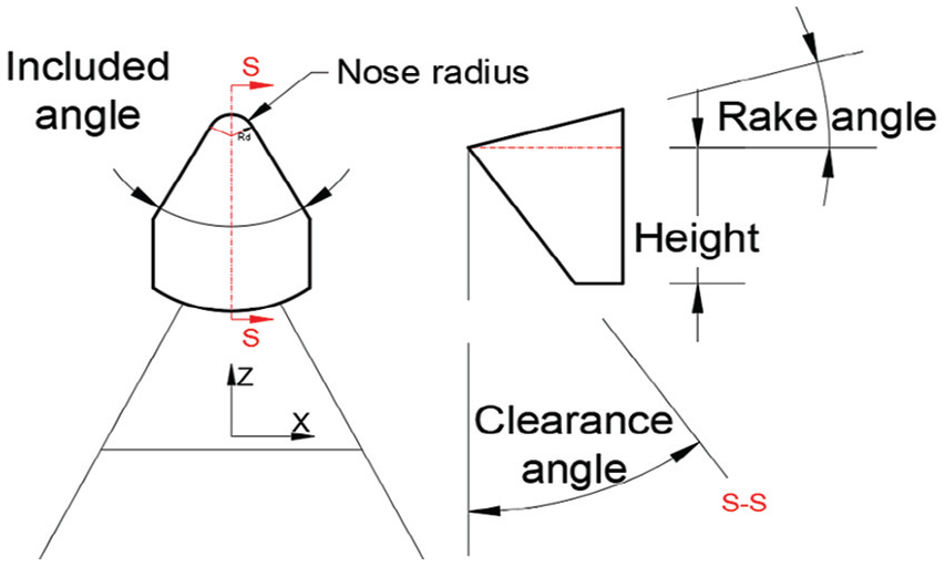
Typical diamond cutting tool geometry.
The freeform surface consists of various curvature features that need to be considered very carefully in STS machining. The compatibility between cutting tool nose radius and surfaces maximum and the minimum surface is a key requirement to avoid any interference during the machining process.
As illustrated in Figure 2(a), form error can occur when the minimum surface curvature is less than the tool nose curvature, which can be defined as 1/R for both the tool nose and surface. The front clearance angle and tool included angle are dependent and should be less than the maximum surface curvature angle at the tangent point. Figure 2(b) shows the correspondence between the tool clearance angle and maximum surface curvature angle in the Z–Y plane. Dynamically, in the larger sagittal curvature of the surface, the tool acceleration and velocity are higher with the STS machining technique. Thus, the dynamic and kinematic effect of the tool on the surface geometry should be considered.
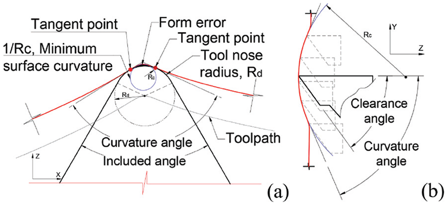
Surface geometry: (a) included angle and curvature angle effect and form error, (b) clearance angle and curvature effect.
Tool compensation
The geometric feature of the diamond cutting tool nose is circular and has a tilted clearance, described as cylindrical or conical. Employing an appropriate tool type for STS machining depends on the surface topology, as mentioned earlier. However, due to the circularity of the tooltip, the cutting edge can suffer with the overcut phenomenon on the finished surface when the toolpath needs to be generated with a greater sag slop. The overcut phenomenon can impair the surface accuracy, causing the final geometry shape not meeting the exact requirements of the proposed surface.
Figure 3 illustrates the effect of the overcutting phenomenon on the toolpath. The conventional TPG in the ultraprecision machining, applying a mathematical shifting algorithm to reposition the compensated points to the tangent point between the tooltip and the surface. However, there are issues with this methods, in that, the mathematical modelling cannot ideally compensate the overcut in very complex freeform surfaces, and the machining process will fail due to the lack of sufficient data-generated points on the surface. With reference to dynamical effects, the stiffness and cutting force is higher in an overcutting position due to material contact penetration, which can lead to a significant mismatch between the machined finished and ideal design surface geometry.
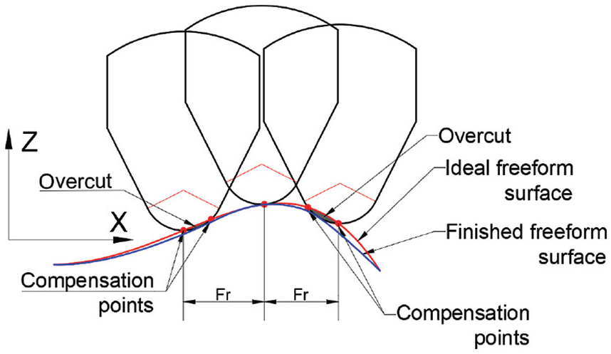
Tool compensation phenomenon.
Multi-body kinematics and precision toolpath generation
Typical diamond turning toolpath generation
Figure 4 shows the typical STS method and the machine configurations, with a cutting tool being mounted on the axis of either the X-slide or Z-slide. A spindle chuck holds the workpiece on the C-axis. The Z-axis is parallel to the spindle axis, and the X-axis is in the perpendicular direction to the Z-axis. Generating the tool motion command as a function of the spindle position and X-slide, location will create the multi-axis synchronisation with the aid of the amplifiers and the programmable multi-axis controller (PMAC). The methodology of TPG, as shown in Figure 4, commonly, can be employed for STS, whereby the toolpath can be generated by controlling the Z-axis translation and the axial X-axis feed system, concerned with polar spindle rotation
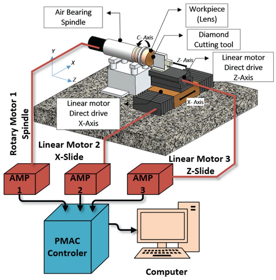
Schematic of the multi-axis control configuration for an ultraprecision diamond turning machine (DTM).
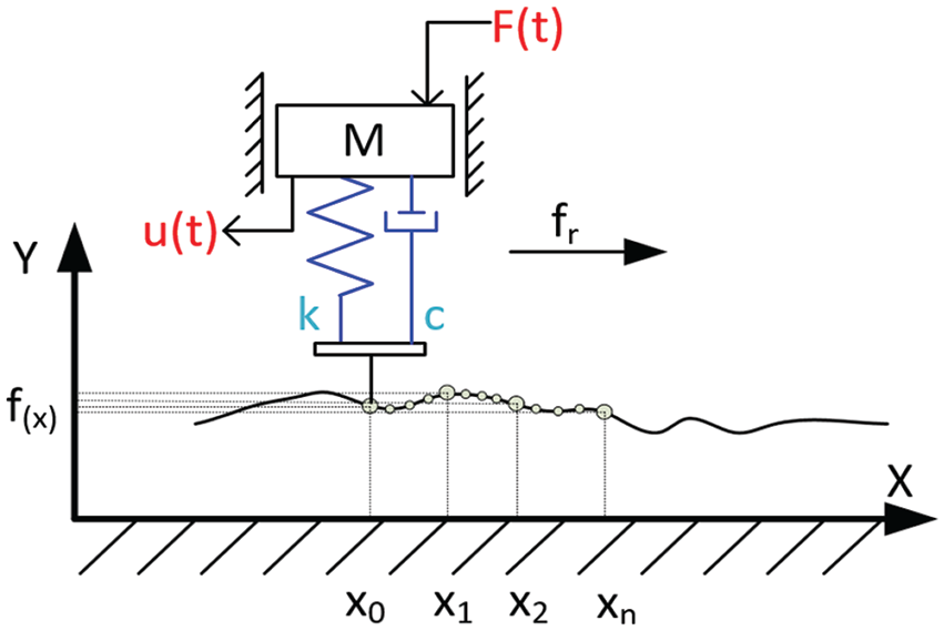
Motion equations
The system can be considered as a simple single degree of freedom mass–spring system, where the mass (m) is affected by the applied force (F) in the direction of (u). The mass is permitted to have a displacement only in the (u) direction, and Newton’s second law for this system is the result, whereby the force is equal to the mass times the acceleration at step time (t)

where,

where,
Equations of motion with a multi-body and multi-degrees of freedom.
The equation of motion is defined by a set of grouped differential and algebraic equations. Integration of these differential equations can obtain the numerical solution for the system to satisfy algebraic constraint equations at each step size of the motion. Numerically, the set of the differential equations is stiff when there is a full distribution between the low- and high-frequency eigenvalues, during the time that the latter is over-damped. In addition, regarding the freeform surfaces and inconstancy of their tangential vectors, running the stiff solver and integrator can obtain the real dynamical solution for generating the toolpath for the CAM system. For solving the stiff system, the stiff integration method is an efficient computational method, whilst other methods for differential equation solving perform very poorly and slowly. Numerically stiff differential equations ensure stiff integration and compute the solution efficiently. 17
Automatic dynamics analysis of mechanical system
Automatic dynamics analysis of mechanical system (ADAMS)/Solver is a method that has a robust algorithm to solve the problem for multi-body systems numerically. This methodology has been employed in this work to generate the toolpath for freeform surface directly from the CAD model. It precisely generates the position output coordination at each time step of the tool motion, while it is in 3D contact with the surface of the workpiece in the CAD model. The ADAMS solver widely uses the Newton method to solve the non-linear equation. Nevertheless, the freeform surfaces can be classified as a non-linear system. The Newton–Raphson algorithm can find the roots

This phenomenon would be advantageous to employ this methodology for TPG in the STS cutting process. Figure 6 shows the principle of the Newton–Raphson methodology, where the function of
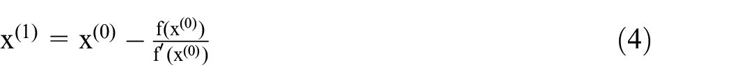

where,
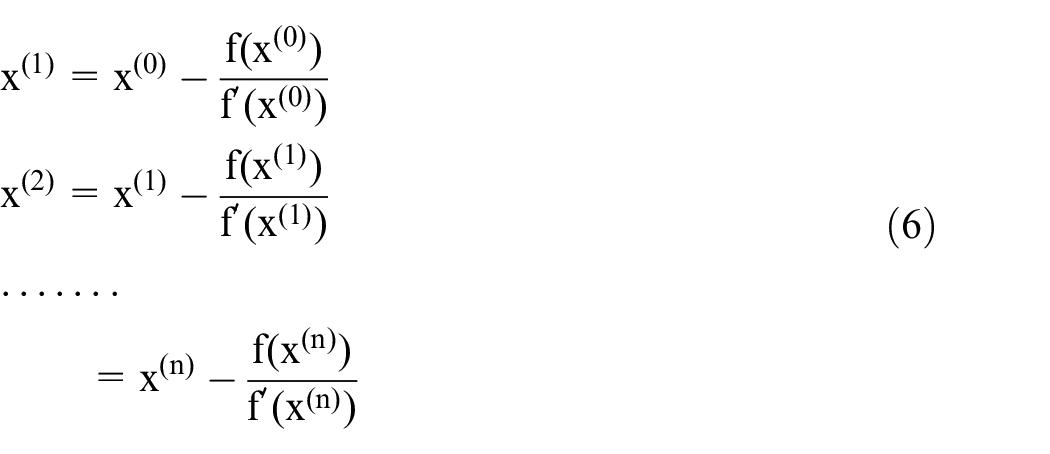
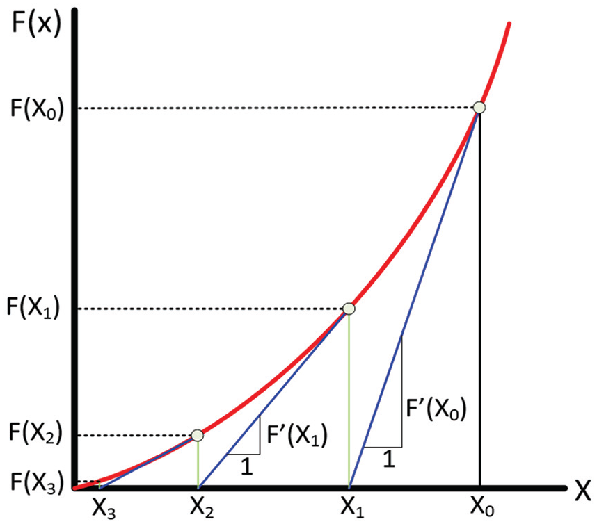
Illustration of the Newton–Raphson method.
Generalised coordination positions
In a dimensional multi-body dynamic system, the position and orientation of the body can be defined by absolute coordinates, which indicate the local reference frame of the origin of the fixed-body and the three local frames of the Euler angles orientation, with the inertial global reference frame, respectively. An additional equation for a constrained multi-body is required to impose the condition of the motion for the system. The generalised coordinate vector for the multi-body can be written as
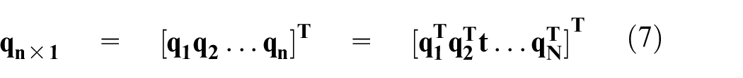
where,

where,

where, t is the time and m are the constraint numbers. The constraint equations can be expressed by differentiation of equation (9) with respect to the time at the velocity level

where the Jacobian matrix can be written as the following arrangement 19
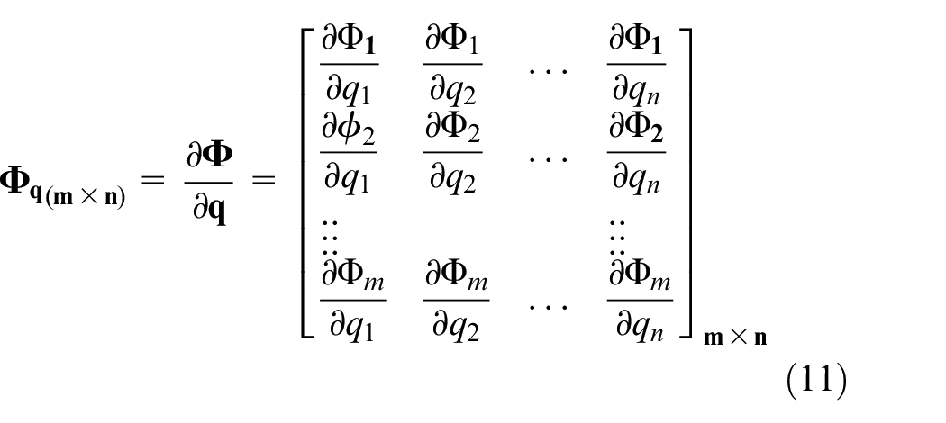
The Jacobian matrix can be written for deducing and representing the acceleration, forces, reaction forces and the positions. For the TPG, the unknown position points will be re-evaluated in the Jacobian forces concerning the time and initial condition and will define the curve by integrating these point at each iteration.
Kinematics analysis and integration of position level
With known initial condition position of the system at time

Using this method can lead to finding the next step with respect to the time for all unknown constraints in the system. The integration process of the equations containing the unknown acceleration and Lagrange Multiplier can be resolved at each integration time step. The most common solver in ADAMS is a direct index 3 differential algebraic equation (DAE), in fact, the differential equations of the position kinematic constraint, as shown in Equation 9. Two common integrators in ADAMS known as Gear stiff (GSTIFF-13) and Wielenga stiff (WSTIFF) have been employed in this research to generate the toolpath. The next section will explain the numerical analysis using the GSTIFF-I3/Solver for TPG of freeform optical surfaces.
Multi-Body dynamic diamond turning toolpath generation
As explained in the previous section, ADAMS solver uses the differential algebraic equation to solve the unknown parameters, which is the Z-axis displacement in this case, and defines the toolpath by using a predictor and corrector algorithm, such as the GSTIFF and WSTIFF integrator, based on the initial condition, dynamic constraints and degrees of freedom of the system. The system can be simplified by utilising appropriate constraint only in the interested components. Figure 7 shows simplified STS machining schematic bodies and constraints only between the workpiece and the diamond tool for generating the toolpath. Rotary motor presents the C-axis and linear motor are in steady X-axis position. The Z-axis is one of the unknown factors, which will be calculated by the ADAMS solver based on the initial force applied to the tool, contact point elastic stiffness, static and dynamic friction coefficient and the maximum damping between the diamond and freeform surface.
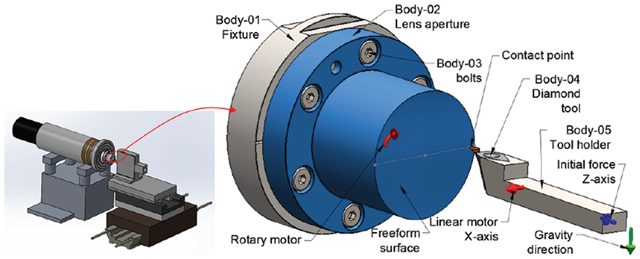
Slow Tool Servo (STS) machining diagram and its schematic multi-body constraint.
As illustrated in Figure 8(a), several constraints such as stiffness, damping and masses will be marked automatically by the ADAMS solver based on the geometry features. The known parameters, such as the initial forces, contacts and machinery motors are user-defined ones. The homing point is the critical point that needs to be specified as ADAMS uses these data for defining the initial condition. Figure 8(b) shows the exact positioning principle that the ADAMS solver uses to generate a path based on the surface geometry and contact. For instance, at position X0 and Z0, at t0, the homing coordination will be marked by the user as an initial condition. At t1, according to the equation of motion (equation (2)), the mass, damping and stiffness matrices,
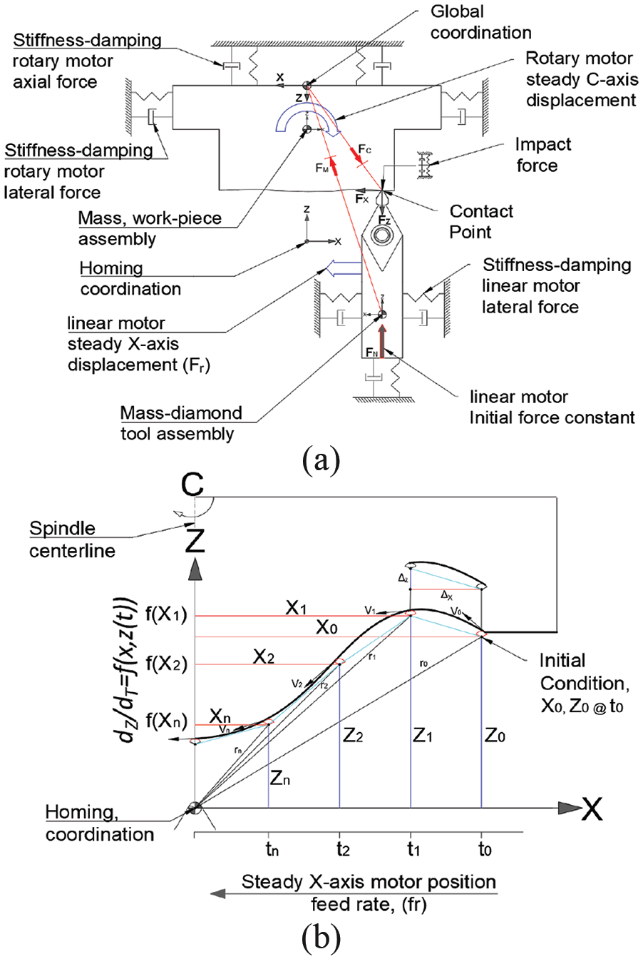
Slow Tool Servo (STS) multi-body dynamic and ADAMS solver principle of exact positioning: (a) constraints diagram, (b) exact positioning.
Numerical analysis and simulation
Toolpath generation using a multi-body dynamic position point and integration
As pointed out in previous sections, the benefit of employing the ADAMS Solver for TPG is that it can overcome the potential gap in ultraprecision freeform cutting using a DTM. As mentioned earlier, most TPG methodologies in ultraprecision machining use a projection map-point spiral two-dimension (2D) sketch converted into 3D freeform surfaces, which can cause severe problems during the cutting process. ADAMS TPG is not just limited to delivering very high accuracy on complex freeform surfaces, for it can also simulate the dynamical and static parameters within the process, such as contact forces, dynamic friction, static friction, mass distribution for balancing, momentum, angular and linear acceleration, velocity and displacement. Moreover, it could be very beneficial for in-line measurement, where the output data can be directly computed during the cutting process. To fulfil the principal of this new method, Solidworks Motion has been employed in this research, which has an interface with the ADAMS/Solver.
As proposed, the principal idea is to discover a solution by linking the CAD model straight to a CAM system with all dynamic and kinematic parameters included, for an ultraprecision machining process of complex freeform surfaces. For successful fulfilment of this, a freeform surface has been modelled, and an ADAMS simulation has been set up with the specification data illustrated in Table 1.
Motion study simulation input data.
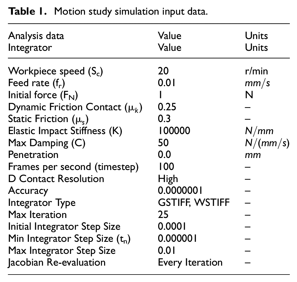
As per the specification, in the ADAMS solver, the known parameters should be set up as an initial condition, and several unknown factors will be defined automatically by the solver, which in this case, the displacement of the cutting tool with respect to freeform surface topology in the Z direction is interested. Accordingly, the angular velocity of the workpiece, acceleration, linear reaction forces, contact forces, momentum and linear displacement in all degrees of freedom at each step time can be determined as an output.
The assumption can be made in such a way that the tool can be recognised as an indicator of what can be in contact and moved very smoothly across a surface that has intense and high-resolution properties.
Based on this phenomenon, as illustrated in Figure 9, the probe, which has a tangential constraint with a freeform surface and normal force
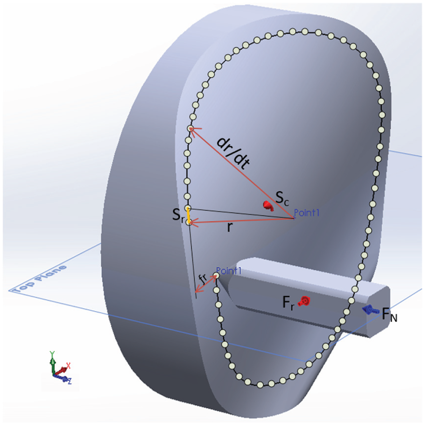
Generalised toolpath points from Jacobian re-evaluation.
The impact stiffness, damping and penetration constraints are also needed, as they will compute the displacement at the next time step based on the material contact between the tool and the workpiece. As illustrated in Figure 9, after running the solver, the initial condition of both angular velocity of the spindle and linear motor become time dependent and will be computed by ADAMS. At each time step, by employing the Newton–Raphson method, whilst the next position will be calculated. Displacement of the so-called indicator in the Z direction at the X–Z plane will be defined based on the geometric shape, according to the angular velocity of the spindle on C-axis and linear motor feed rate on the X-Axis from the origin coordination mark. As the spindle rotates, the linear motor moves towards the centre of workpiece, and at each time step, the positioning coordination of that point will be recorded, whilst all stiffness, damping and mass matrix will also be indicated based on the motion equations. The arc distance of
Typical TPG methods, with map-to-map point projection, experience major problems when they need to be compiled in the real cutting environment and machining process. Due to contact and the friction force between the tool and the freeform surface, most of the generated points will be correlated with error on the final finished surface and thus, this approach cannot generate high performance and accuracy resolution in the complex freeform surfaces. The aim is to reduce the level of these errors by including the friction and contact force parameters into the system and output the computed points based on the dynamic equation of motion. Figure 10 shows the diagram of the force distribution for each individual displacement point that ADAMS can include at each step time on the freeform surface, unlike other typical methods that only cope with map to map point projection onto a surface.
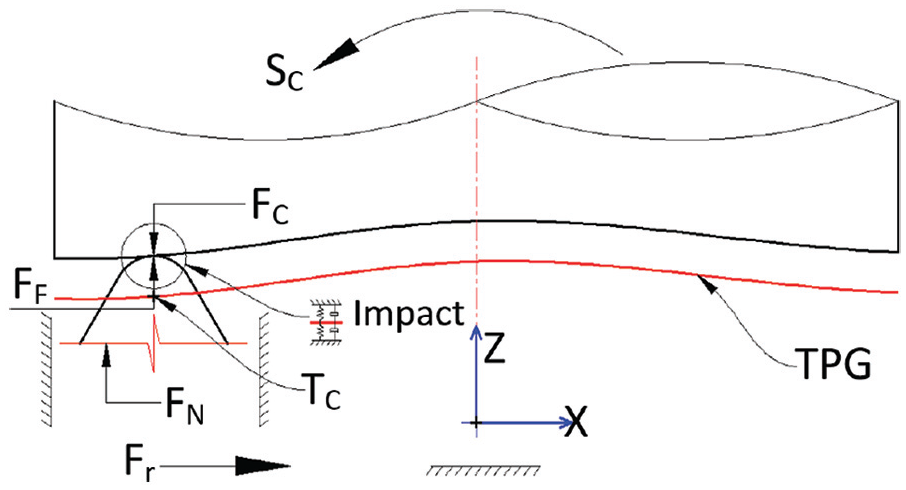
Toolpath generation diagram based on the ADAMS solver strategy.
Upon running the system, as aforementioned, the contact between the tool and surface are under impact stiffness and damping forces, which are illustrated as
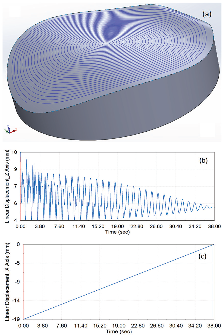
Toolpath-final generalised curve: (a) final and finished curve with 50 r/min and 0.5 mm/s, (b) tool displacement in the Z-axis, (c) tool displacement in the X-axis.
Toolpath generation principle in ultraprecision machining and efficiency
In this study, the main aim and objective was to overcome the significant problems in recent ultraprecision machining. The lack of efficiency is due to the nature of freeform surface complexity and the requirements for high precision and accuracy; thus, the machining setup requires more time application. Figure 12 illustrates the principle of ultraprecision machining using multi-body TPG, whereby the CAD model can be directly imported into the CAM system. As can be seen from the diagram, the multi-body dynamics analysis is part of the ultraprecision machining process that can assure the output data of TPG for the freeform surfaces will succeed the machining dynamics in a very efficient way.
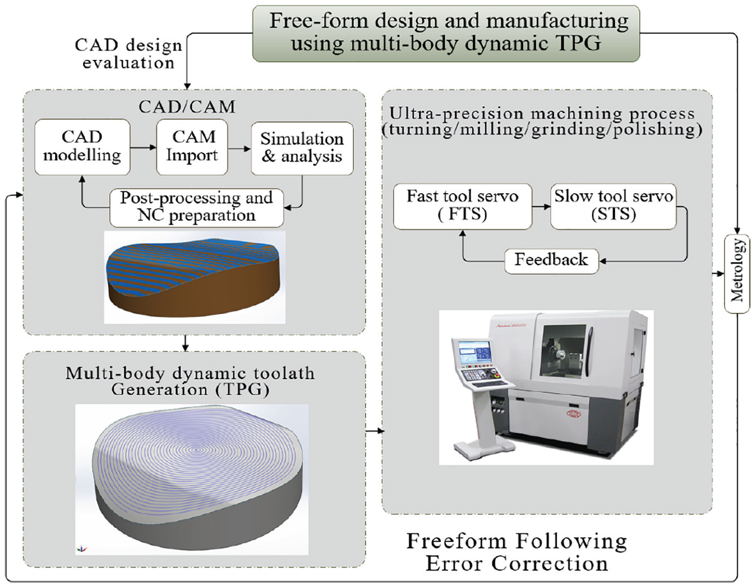
Ultraprecision machining principle diagram using multi-body TPG.
Results, analysis and discussion
As specified, the displacement relatively between the tool and workpiece surface in the Z direction can be defined by the ADAMS algorithms, and these output data can be computed for a CAM system. In a DTM, the X and Z axes form the primary plane for tool displacement. Moreover, the points generalised in the X and Z directions with respect to the time step will define the NC-file and G-codes required for STS machining in the CAM system. Either rotational or linear motors with their relevant factors are simulated, and the output data points generated can be communicated very precisely with the CAM system. In this case, to prove the method works, a manual post-processing has been employed by extracting the output data from linear tool displacement in the Z and X directions component. The Y direction linear displacement is counted as zero as it is located at the centre of the workpiece. The post-processing can be automatised by applying an application programming interface (API) in the ADAMS.
Surface and contact accuracy
The accuracy of the generated point plays the major role in ensuring the feasibility of using this technique in the CAM processing. As aforementioned, precise 3D contact factor between the tool and freeform surface has a significant impact for a successful TPG. With the DTM using the STS technique, the workpiece has a low velocity, and this can be very beneficial for providing a high resolution and accurate toolpath along the freeform surface, as the integrator has sufficient time to compute the generalised points from the Jacobian re-evaluation integrator. The more precise the surface contact the more accurate the generalised of the step points.
According to Table 1, for an angular velocity of 20 r/min, and 0.01 mm/s of linear velocity, the tool travels 30 microns along X axis per one rotational cycle. To prove this movement and displacement, Figure 13 shows the generated points at the beginning and end of one rotational cycle. From the interpretation point of view of the generated point coordination in X, Y and Z directions, it can be clearly observed that
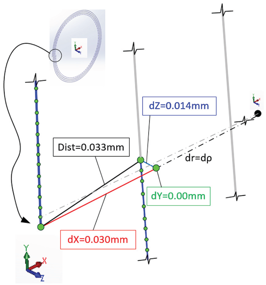
TPG accuracy per cycle.
Integrator step size and its impact
ADAMS solver works based on points integration at each time step and generate the curves. The impact of the size of the time step is significant for achieving a micro–nano resolution in the TPG. Further, simulation and investigation are required to prove the argument. Figure 14 shows two different simulations with different step sizes that have been employed to do so.
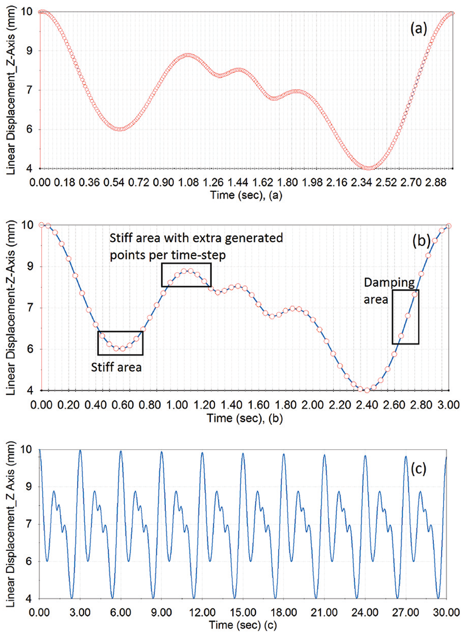
Toolpath characteristic influence of time step size: (a) time step size of 100 units per second, 0.01 s; (b) time step size of 20 units per second, 0.05 s; (c) full cycle of Z-axis displacement after 30 s with a step size of 100 units per second.
As shown in Figure 14(a), the step size is set to 0.01 s, while Figure 14(b) shows the setup for 0.05 s. The time domain in simulation (a) is shorter than simulation (b). The diagram illustrated in Figure 14(b) shows that more points have been generated in the stiff area and less in the damping area of the freeform surfaces, with respect to the step time. From this point of view, the comparison can be made, thought that, in typically TPG methodology, the points will be generated with constant increment with respect to the step time.
The meaning can be defined that when the step size is short, the computing of the next point based in Newton–Raphson methodology will be closer to the root. Hence, it can be concluded that variety of the points can be generated within the specified step time based on the freeform shape and geometry. For example, in simulation (a), 100 points have been generated per second, while simulation (b) has calculated 20 points per second. It can be proven that simulation (a) has much more accuracy and resolution in which considerably can provide precise positioning in the ultraprecision machining using STS technique. Finally, Figure 14(c) shows the full-cycle simulation for running the solver for 30 seconds. As shown, at each cycle, the amplitude of the displacement of the curve decreases as it moves towards the centre of the workpiece.
Whilst ultraprecision TPG using the ADAMS solver can take a longer time to generalise the precise coordination points within the surface topology due Jacobian iteration and re-evaluation, the technique can be optimised with additional functions to overcome this disadvantage. The initial integrator step size is the major factor of controlling the speed of simulation. For instant, by increasing this value, the simulation can be run much more quickly. Also, increasing the minimum integrator step size to its lowest value can decrease the simulation time as it enters to the lower bound of the integration much instantly. The upper bound of maximum integrator step size is also influential as it can deal with the contacts that are required to detect the impact and stiff points during the simulation. Setting this value to the highest level can optimise the various factors mentioned.
Influence of friction and displacement
Dynamic and static friction have been employed in this TPG methodology, which makes it unique in comparison with other classes of typical TPG. The friction constant along with other parameters, such as vibration and thermal drift, have a significant impact on the operation of real-time ultraprecision machining. In this study, the friction has been modelled as typical Coulomb friction, which represents the dynamic resistive force between the tool and freeform surface. According to Table 1, in this study, the dynamic and static friction coefficients have been assigned as the contact friction based on dry steel material. However, from advantage point of view, the most appropriate material friction details can be specified for the contact set in ADAMS to employ the Coulomb friction method to solve the total friction force at each time step points. Also, this method could be extremely beneficial in future for studying the cutting force during the machining process and in-line measurement for ultraprecision manufacturing of freeform optical surfaces.
Figure 15 shows the impact of the friction force with respect to displacement at the Z-Axis. Apparently, the friction force increases when the tool is in contact with the surface, where the gradient or the slope of the surface is very high. As aforementioned, the freeform non-rotational surface is represented as a non-linear system and can be recognised as being a stiff one. The blue curves represent the displacement in the Z-direction, and the red curve is the magnitude friction force. It can be seen that the highest stiff value is triggered at the location in the surface where the curvature of the surface suddenly changes from concave to convex, and the friction forces are vary at this positions. Further, the validation of the system proves that the form error displacement of the tool generated in the Z-direction is relative to a friction force and hence, these points after post-processing in the CAM system will have less error in the final toolpath required for the machining. The approach can be very helpful in finding the errors in direct drive motors during the machining operation and prepared for appropriate tuning.
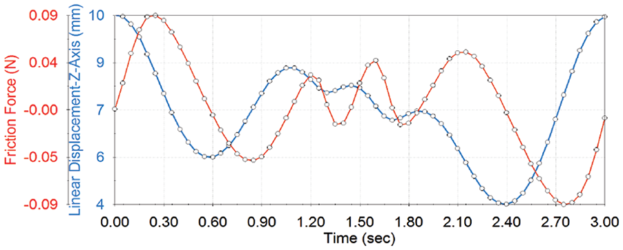
Toolpath characteristic influence of Z-axis displacement versus friction force.
Experimental trials and computer-aided manufacturing validation
In this research work, a set of experimental trials has been prepared for the ultraprecision machining of the freeform surfaces applying proposed multi-body dynamics TPG methodology. Figure 16 shows the ultraprecision diamond turning for this method.
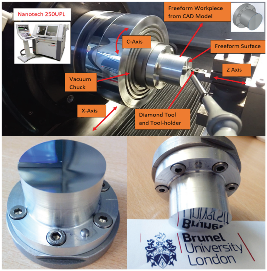
Photograph of the diamond turning machine for the experimental trial and validation of CAM post processing.
For the experimental preparation, the generated displacement points in the X–Z plane have been extracted from ADAMS numerical simulation, and the NC file has been created for CAM post-processing. Evidently proved from the NC file that very accurate displacement in the X and Z axes in the range of less than 10 nm has been obtained. The experiments were carried out for final validation of the ADAMS TPG. Also, a comparison was made between traditional ultraprecision machining TPG and ADAMS, with NanoCAM software being employed for validation. The experiments were run using Moor Nanotech 250UPL. Table 1 shows the setup data for TPG based on the ADAMS methodology. For accurate result, the spindle speed and frame per second increased to 60 r/min and 3600 frame, respectively. The angular distance in C-axis increments was calculated as 0.1 degree which can be defined by dividing a circular cycle of 360° over the frame per second, 360/3600 = 0.1°.
Figure 16 illustrates the machining process for the experiments, with the STS machining technology being used. Two different workpieces with the same geometry shape have been used, one to test the effect of the surface resolution with the NanoCAM methodology and the second to test the novel multi-dynamic TPG, which in this article known as ADAMS technique. An aluminium alloy material was selected for machining. The same diamond tool geometry with a 0.6 mm tool nose radius was used for both experiments. The machining parameters for the NanoCAM NC code were set as 20 r/min with constant angular point distance of 0.1°, 0.01 mm stepover feed in the X direction.
Toolpath accuracy
The comparative results from the experiments show that the ADAMS toolpath computed precise points almost similar to or above those generated with NanoCAM software. Figure 17(a) compares the accuracy between the two methods, as described in the previous section, and it can be observed that a maximum division (error) of 5 nm was experienced from the NC file in one cycle per step time. Figure 17(b) illustrates the final computed points based on the ADAMS methodology for the X, Z and C axes. The integration points generated by Jacobian evaluation provide validation of the accuracy and smoothness of the toolpath curve. Figure 17(c) shows a range of 0–0.5 mm of sag height in the freeform surface. It is apparent that the highest accuracy is accomplished with such a large amount of surface sag with the ADAMS toolpath experimental process.
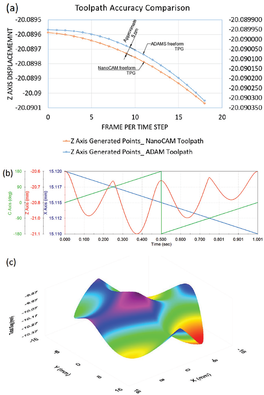
Toolpath final generalised curve: (a) comparative accuracy diagram ADAMS vs NanoCAM; (b) generated displacement points in the C-axis, Z-axis and X-axis; (c) ADAMS toolpath sag evaluations.
Surface roughness measurements
A Zygo 3D surface profiler was employed for the final measurement validation. The surfaces roughness in both the machined components of ADAMS and NanoCAM have been measured, and a comparison accordingly made. Figure 18 shows the measured surface roughness of the freeform surfaces. Comparing the two results, it can be seen that the surface machined by the ADAMS toolpath has lower surface roughness due to the very precise contact points evaluated by the Jacobian predictor and the GSTIFF/WSTIFF integrator. Based on the results shown in Table 2, it is evident that the maximum values of the PV, Rms and Ra in the ADAMS tool path generation are less than when undertaken by the NanoCAM process.
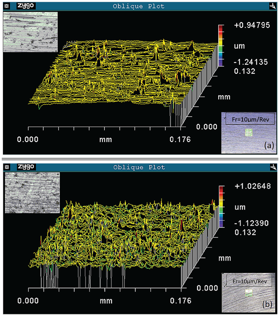
Measurement results of the surface finishing profile: (a) using ADAMS TPG, (b) using NanoCAM TPG.
Surface finish profile comparative data.
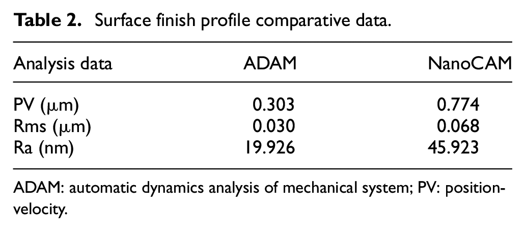
ADAM: automatic dynamics analysis of mechanical system; PV: position-velocity.
Conclusion
In this article, an innovative TPG approach for ultraprecision machining has been proposed based on the automatic dynamics analysis of precision engineering systems. The approach can be effectively implemented for ultraprecision machining of freeform optic surfaces using diamond turning. The approach also can be integrated with the conventional TPG methods for dynamic and kinematic investigation purpose in freeform surfaces. In this approach, the toolpath for very complex surfaces can be generated using the Newton–Raphson method to solve the kinematics and dynamics equations of the multi-axis motions. The proposed method additionally can overcome the issues currently existing in ultraprecision machining using the conventional CAM system, such as form error and compensation malfunctioning. The effect of friction and contact force have been studied, and very accurate toolpath curves can thus be generated. The impact of the points integration methodology and Jacobian re-evaluation have been investigated, with it being concluded that the time step size plays a critical role in generating the toolpath with high accuracy and resolution. Different types and factors for the time step have also investigated, showing that decreasing the step size will increase the generated points and thus, increase the accuracy of the integrator. Finally, GSTIFF/WSTIFF solver for solving the non-linear equations of motion has been studied.
Footnotes
Declaration of conflicting interests
The author(s) declared no potential conflicts of interest with respect to the research, authorship, and/or publication of this article.
Funding
The author(s) disclosed receipt of the following financial support for the research, authorship, and/or publication of this article: This work is supported by funding from Brunel University London and the UK EPSRC PhD Scholarship.