
Abstract
Parametric interpolation obtains a great success in three-axis surface machining with smooth motion, high accuracy, and high machining efficiency, but does not go well in five-axis surface machining due to lack of appropriate and efficient methods of tool path generation, interpolation, and three-dimensional cutter compensation. This article proposes a triple parametric tool path interpolation method for five-axis machining with three-dimensional cutter compensation, which proposes an appropriate triple parametric tool generation method for realizing the three-dimensional cutter compensation in five-axis parametric interpolation. A triple parametric interpolation algorithm is also proposed to realizing the simultaneous interpolation of the source data, which ensures the primitivity and maintains the accuracy. The proposed three-dimensional cutter compensation can compensate the errors caused by minor changes in cutter size, thus machining accuracy can be improved. Finally, illustrated example verifies the feasibility and applicability of the proposed methods.
Keywords
Introduction
Parametric interpolation has been proved to have great advantages over conventional linear and arc codes,1–7 such as smoother motion, shorter machining time, and higher accuracy. Many scholars have made great progresses in realizing fast and accurate parametric interpolators in three-axis machining, but few can be found in five-axis machining. Five-axis computer numerical control (CNC) machine tools could control three linear axes and two rotary axes to move synchronously. The cutter position and orientation could be determined at the same time, so that it could better adapt to the workpiece surface. With the advantages such as shorter machining time, higher machining accuracy, and less amounts of fixtures than three-axis machining, five-axis machining is widely used to machine impellers and structural parts in aviation and space industry. Thus, realizing the parametric interpolation in five-axis machining is indeed a valuable work to further increasing the machining efficiency and machining accuracy.
Bohez 8 analyzed the kinematic chain in five-axis milling machine tools, which classified the possible conceptual designs and actual existing implementations based on the theoretically possible combinations of the degrees of freedom and defined some useful quantitative parameters, such as the workspace utilization factor, machine tool space efficiency, orientation space index, and orientation angle index. This article offered a basic principle for analyzing the kinematic transformation of five-axis machine tools. Wang and Chen 9 proposed a real-time non-uniform rational basis spline (NURBS) surface interpolator for five-axis surface machining with flat-end cutter, which used Taylor series expansion method and coordinate transformation to deduce and implement the algorithms of NURBS interpolation, cutter effective machining radius, cutter offsetting, and inverse kinematics. However, the proposed method did not consider the dynamic constraints and did not offer a standard NC code format. Later, Wang et al. 10 integrated a five-axis spline interpolation controller in an open CNC system, which proposed both a five-axis spline interpolation command format with representing the position spline and orientation spline together and interpolation strategy. However, the three-dimensional (3D) cutter compensation was not integrated in the system. Beudaert et al.11,12 proposed a feedrate interpolation algorithm for five-axis NURBS interpolation with considering axis jerk constraint, which can generate smooth feedrate profile for all axes under confined dynamics. However, the proposed method was an offline algorithm with many iterations. Liu et al. 13 proposed a dual NURBS tool path interpolation for five-axis machining with controlled angular velocity. The proposed method did not use a NURBS curve to represent the cutter orientation vector but the two angles of the two rotary axes, thus the angular velocities of the two rotary axes can be controlled when determining the next sampling points in real-time interpolation. Sun et al. 14 proposed an adaptive feedrate scheduling method of dual NURBS curve interpolator for precision five-axis CNC machining with using a curve evolution strategy. Yuen et al. 15 presented an algorithm for generating smooth trajectory with using high-order smooth parametric spline to fit the cutter positions and cutter orientations. Wang et al. 16 implemented the five-axis transformation function in a conventional CNC system for five-axis G1 tool path interpolation. Zhou et al.17–20 proposed an adaptive feedrate interpolation with multi-constraints for five-axis parametric tool path. However, the aforementioned works did not implement or consider the five-axis parametric interpolation command format, five-axis parametric interpolation strategy, five-axis transformation function, and 3D cutter compensation in the same time, thus none of them can be applied to real machining applications.
In order to realize a feasible and applicable parametric interpolation for five-axis machining, this article proposes a complete scheme to solve this problem. First of all, a triple parametric tool path command format is proposed, which represents not only the cutter location (CT) curve and cutter orientation (CO) curve but also the cutter contact (CC) curve. Moreover, the algorithms for generating the triple parametric tool path are also presented. Second, algorithms for five-axis transformation and 3D cutter compensation are proposed. Third, interpolation method for triple parametric tool path is presented. Finally, experiments are conducted to verify the feasibility and applicability of the proposed scheme.
Triple parametric tool path generation
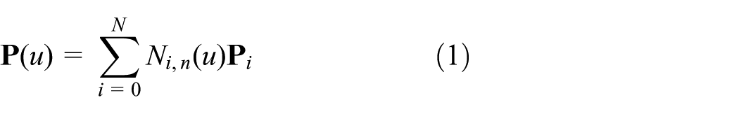
Triple parametric tool path represents the CT curve, the CC curve, and the CO curve. The CT data, CC data, and CO data generated by the computer-aided design (CAD) or computer-aided manufacturing (CAM) systems are fitted to parametric B-spline

Overview of the proposed triple parametric path interpolation.
Parametric tool path fitting
The CT data, CC data, and CO data are first generated into a CLS file shown in Figure 2 by a CAD/CAM system such as UG, the format of which is as follows

where (Xct, Yct, and Zct) denotes the CT points, (Xcc, Ycc, and Zcc) denotes the CC points, and (Xt, Yt, and Zt) denotes the CO vector. The data are saved to a series of CT points

A part of the CLS file.
The CT B-spline is fit to pass through all the CT points, which can be defined as
where n is the degree,

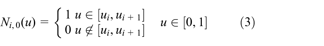
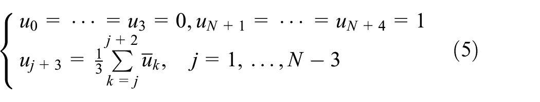
In order to obtain the CT B-spline, the knot vector and the control points should be calculated first by the series of CT points. In equation (1), the number of control points is set equal to the number of CT points. The degree of B-Spline is set to 3. Parameter values,

Then, the knot vector is solved as follows
Since the knot vector is solved, the basis functions in equation (1) at any parameter u are known. In addition, since each CT point has been assigned a parameter value based on equation (4), it is possible to solve for the control points
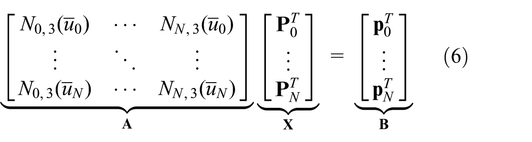
The control points are obtained by

Once the knot vector and the control points have been obtained by the aforementioned processes, the third-degree B-Spline of CT curve
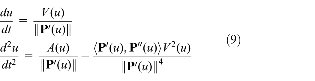
Tool path interpolation
The triple parametric tool path
Let parameter sets

where
where
After the parameter u in the ith sampling period is determined by equation (8) as


with equations (10) and (11), the original data

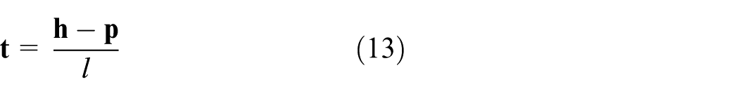
3D cutter compensation
When planning the trajectory in CAD/CAM systems, the cutter length and cutter radius are predefined. Once the cutter used in practical machining is not the same with the predefined one, or the cutter size is changed due to wear, the trajectory must be re-planned in CAD/CAM system, which is a waste of time and decrease the production efficiency. With 3D cutter compensation, the minor changes in cutter size in radius or length compared with the predefined one can be compensated. There is no need to change another cutter or generate a new trajectory. In this section, the 3D cutter compensation in end milling is proposed.
Figure 3 shows the schematic diagram of torus cutter end milling. Positions
Vectors
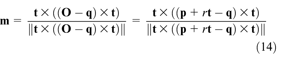

If the radius R has a change of

When the small radius r is equal to 0, then the cutter becomes a flat-end cutter, and the compensation equation becomes as

When the radius R is equal to the small radius r, then the cuter becomes a ball-end cutter, and the compensation equation becomes as

The CT point
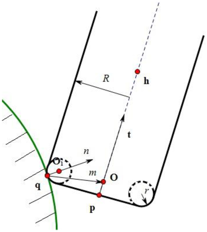
Schematic diagram of torus cutter end milling.

Trajectory planning for machining a rotor blade of aviation engine in UG.
Illustrated example
The proposed triple parametric tool path interpolation method with 3D cutter compensation is validated in the following simulations and experiments. The parameters involved in the following experiments are listed in Table 1.
Experimental parameters.

The example is a rotor blade of aviation engine shown in Figure 4. The trajectory is first planned in UG, and then, the CLS file of G1 tool path with CT points, CC points, and CO vectors is generated. Figure 5(a) shows a part of the G1 tool path with cutting tool, CT curve, and CC curve. The triple parametric tool path generation method proposed in section “Parametric tool path fitting” is utilized to fit the CT points, CC points, and CO points to third-degree B-spline parametric curves, which are shown in Figure 5(b).
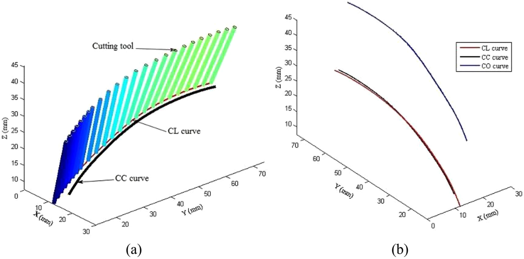
Triple parametric tool path generation based on G1 tool path for machining a rotor blade of aviation engine: (a) trajectory planning results in CAD system and (b) CT curve, CC curve, and CO curve after triple parametric tool path generation.
As the CT curve is very even, the feedrate for the CT curve can be generated very evenly as shown in Figure 6. The CC curve and CO curve are interpolated as follow-up of the CT curve interpolation by using equations (10) and (11) to ensure the simultaneous interpolation of the corresponding CT point, CC point, and CO vector, by which the primitivity of the source CLS data can be maintained, thus the generated triple parametric tool path will not violate the source data, and the accuracy can be enhanced.
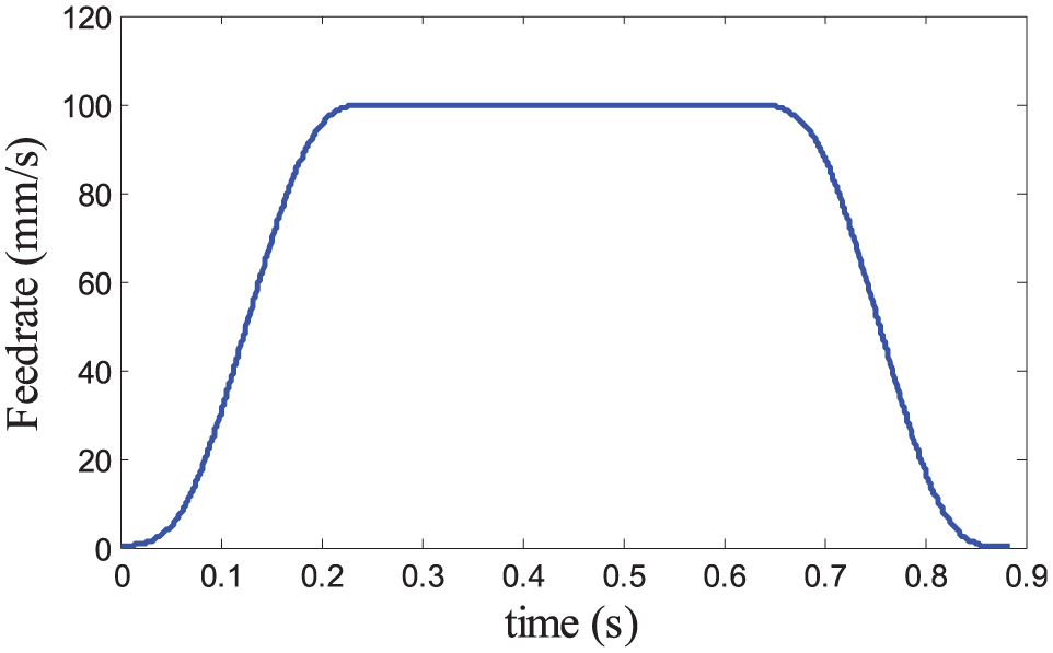
Feedrate planning of the CT curve.
The cutter used in generating trajectory by CAD system is a ball-end cutter with 10 mm diameter. If the actual used cutter has the same diameter size of the cutter used in generating trajectory, the actual interpolated positions are accurate. Once the size of the actual used cutter has changed, the actual interpolated positions without 3D cutter compensation are inaccurate, thus the quality of machined surface is deteriorated. The proposed triple parametric tool path interpolation with 3D cutter compensation can solve this problem.
Suppose the actual machining cutter has a change of 0.01 mm in radius, that is, the actual cutter diameter is 9.98 mm, without 3D cutter compensation, the CT positions used to drive axes are inaccurate, which lead to spatial errors and reduce the machining quality. With the proposed 3D cutter compensation, the CT positions can be corrected to the accurate positions, thus accuracy can be ensured. Figure 7 shows the compensated distance with the proposed 3D cutter compensation, which is the distance between the compensated and uncompensated CT positions. It can be seen in Figure 7 that the maximum compensated distance is 9.4 µm and the minimum compensated distance is 3.2 µm, which is very significant for a change of 0.01 mm in radius.
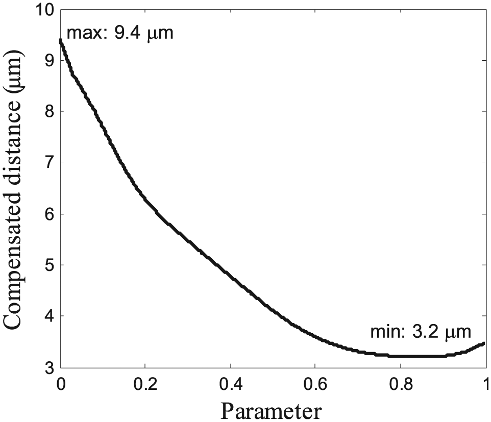
Compensated distance between compensated and uncompensated CT positions.
The five-axis CNC experiment platform based on TwinCAT is developed independently as shown in Figure 8, and the five-axis machining with 3D cutter compensation algorithm proposed in this article is realized as shown in Figure 9. And the complex curve surface is used for the actual machining verification, which is shown in Figure 10.

Open architecture NC system platform.
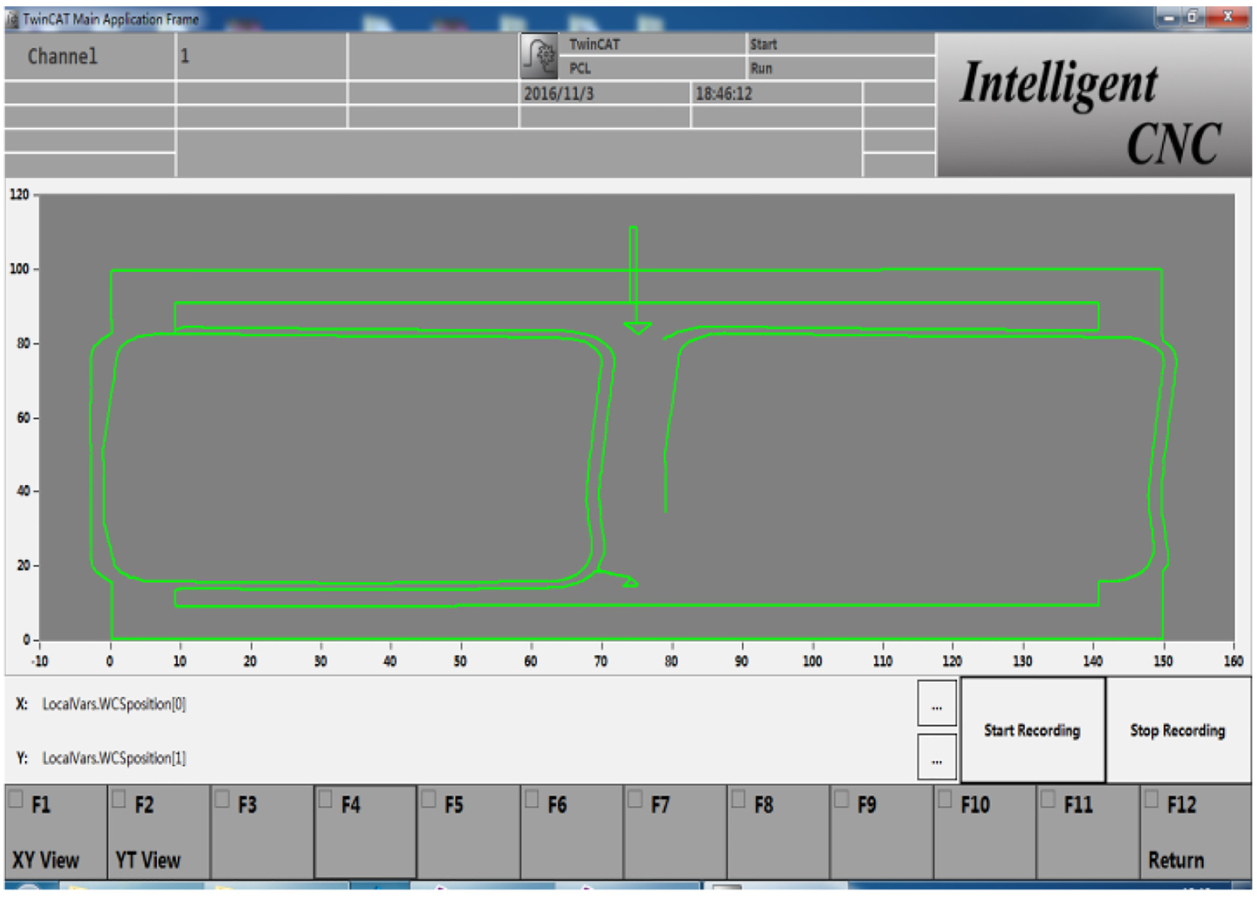
Tool compensation system software interface.

Machining workpiece.
Conclusion
This article proposes a novel triple parametric tool path interpolation for five-axis machining with 3D cutter compensation, which successfully integrates the 3D cutter compensation in five-axis parametric interpolation. The algorithm for generating triple parametric tool path and the proposed triple parametric interpolation method maintain the primitivity of the source data, thus accuracy can be ensured. Five-axis kinematic transformation and 3D cutter compensation can easily compensate the errors caused by minor changes in cutter size. Based on TwinCAT’s open CNC system platform, the algorithm simulation and processing verification can meet the processing requirements, and the correctness and realization of the algorithm are confirmed. This article provides feasibility verification for the research of space tool compensation algorithm for numerical control system.
Footnotes
Acknowledgements
The authors would like to thank the anonymous reviewers for reviewing this paper.
Handling Editor: Jaber Qudeiri
Declaration of conflicting interests
The author(s) declared no potential conflicts of interest with respect to the research, authorship, and/or publication of this article.
Funding
The author(s) disclosed receipt of the following financial support for the research, authorship, and/or publication of this article: This work was supported by the National Natural Science Foundation of China under Grant No. 11290144 and Science and Technology Project of Hebei Province (No. 17211812D).