
Abstract
A novel milling force model for cutting aviation aluminum alloy 7075 using carbide end mill is established in this article. A two-dimensional end-milling model is set up to investigate the influence of tool geometric parameters on milling force with the single-factor analysis. The relationship between milling forces and tool geometric parameters is obtained by nonlinear regression fitting method. Based on the existing empirical model of milling force, quadratic polynomial factor is taken into consideration to explore the influence of tool geometric parameters on milling force. Thus, a novel milling force model is built up which includes tool geometric parameters and milling parameters. The coefficients of the novel model are identified by the direct method and the loop method. The precisions of the coefficients obtained by the two methods are compared between prediction values and experiment values. After comparison, the model whose coefficients are obtained by loop method has higher prediction ability. End-milling experiments were carried out to verify the prediction accuracy of the novel milling force model. The result shows that the novel model of milling force has high accuracy in prediction. The method of building the milling force model proposed in this article can be applied to other types of milling cutter.
Introduction
Milling process has been extensively applied for die components, and aeronautical or biomedical parts made of metal alloys, such as Ti-, Ni-, and Al-based alloys, due to their excellent mechanical properties.1,2 During high-speed milling, the milling force has an important influence on the tool life, surface quality, vibration stability, cutting tool, and workpiece machining deformation. This is why a precise prediction of milling force is so essential to select machining conditions. 3
The existing milling force models were divided into following categories: empirical model, analytical model, artificial intelligence model, and finite element method.4–7 In the empirical model, the related factors influencing milling force are expressed in the form of coefficients and exponents. 8 Ren J et al. 9 combined the grey correlation with Taguchi’s method to analyze the relationship between tool geometric parameters and cutting forces, surface roughness, and acceleration. That is to say, the accuracy of the empirical model depends on a lot of experimental data. The analytical model is based on the shear theory proposed by Merchant.10,11 He deemed that cutting process was the shear deformation of the metal layer of workpiece generated along the shear plane under the effect of tool rake face. In the analytical model, cutting area, friction angle, and shear angle are calculated to simulate the mechanical mechanism of milling process. Chen D et al. 12 predicted the milling force of variable helical angle milling cutters using analytical method and verified with experiments. However, due to the influence of high strain rate, elastic–plastic deformation, and high rate of temperature change, the related angles and the mechanical mechanism of cutting face could not be obtained accurately. Artificial intelligence model used artificial neural network technology to effectively deal with the related parameters which affected the cutting force. Wang and Huang 13 used the improved back propagation (BP) neural network to establish the neural network model of the milling force and optimized the process parameters. Zheng 14 applied the particle swarm optimization of artificial neural network theory to the high-speed milling force model. The finite element model discretizes the continuum into a set of finitely sized elements to solve the continuum mechanics problem. Wang L et al. 15 used the professional finite element software, providing access to varying speed cutting force changes.
In the models above, milling force is a function established respectively with the parameters of milling three elements, shear angle, cutting force coefficient,and so on. On some occasions, these models could predict the milling force accurately. However, few models have taken into consideration the influence of the cutter geometrical structure on the milling force, and few scholars have done research on the relationship between the cutter geometrical structure and the milling force. Actually, in all the models mentioned above, it is important to note that the coefficients of models have to be determined in advance for each specific cutter and then to be used under different cutting conditions. In other words, cutting force coefficients have to be renewed whenever the geometry of cutter is changed. 16 This article is based on a two-dimensional (2D) milling simulation model of solid carbide end-mill milling aviation aluminum alloy 7075. The influence of tool geometric parameters on milling force is studied; the corresponding mathematical model and a novel milling force model which contain tool geometric parameters and milling parameters are built through the finite element simulation. And a milling experiment has been set up to verify the predictive accuracy of the novel model by comparing the predicted values and the experimental values.
Finite element analysis on milling force
Tool material and geometric angle
Aviation aluminum alloy 7075 has several advantaged properties such as low yield strength, less hardness, good thermal conductivity, and low cutting force. So, there are a lot of cutting tool materials suitable for processing aviation aluminum alloy 7075, such as high-speed steel, cemented carbide cutting tools, and coated tools. However, high-speed steel is unsuitable in high-speed milling process because of its bad wear resistance; coated tool would reduce the surface quality of workpiece because of the diffusion from coating to workpiece. Therefore, ultrafine-grain-cemented carbide material, which is widely used in the actual aviation enterprise, is selected as the tool material in this article.
Geometrical structure parameters of tool edge have extraordinary important impact on milling process. The selection of milling tool includes not only cutter’s material and type but also some other important geometrical parameters: diameter, blunt round radius, helix angle, rake angle, and relief angle. For the convenience to carry out single-factor analysis, geometrical structure parameters of end mill in this article are 16 mm in milling cutter diameter, 0.01 mm in blunt round radius, 30° in helix angle, 15° in rake angle, and 8° in relief angle.
Finite element milling model
No matter how complex the tool structure is, the cutting part can be regarded as the evolution of the turning tool. In milling, the main section reference is produced in the process of cutting out perpendicularly to the axial direction of the tool, as shown in Figure 1(a). After that, the cutting length is kept unchanged, while the feed thickness changes with the change in cutting position, as shown in Figure 1(b). Milling can be roughly transformed into orthogonal turning of cutting thickness variation. In order to express the cutting mechanism more simply and intuitively, we have simplified the cutting process to 2D orthogonal cutting. In 2D orthogonal cutting, the cutter is simplified to a straight line and a nose arc for the projection of the rake face and the flank surface. 17 Generally speaking, milling is a kind of oblique cutting process, because the helix angle of milling cutter is usually not 0 degree. The main cutting edge and cutting speed direction are not perpendicular, which lead to a change in front and rear corners in the process of actual cutting. In the process of 2D milling simulation, the equivalent tool angle is obtained by tool angle transformation, and the equivalent equation is shown below 18
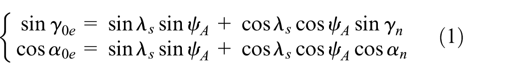
where
Based on cutting simulation software, the models of workpiece and tool are established, as shown in Figure 1. In order to obtain the optimal mesh, the adaptive re-meshing technique is adopted.

Milling model: (a) Section model; and (b) 2D simplified model.
Influence of tool geometric parameters on milling force
In order to study the law of change of milling force with the change in tool geometric parameters when cemented carbide tool is used in machining aviation aluminum alloy 7075, the single-factor simulation analysis of the geometric parameters of the cutting tool was carried out. The geometric parameters of the cutter were given as mentioned above. Different tool geometric parameters were chosen to carry out single-factor analysis, and then the law of effects on milling force could be concluded. The milling parameters are as follows: the spindle speed was 15,000 r/min, the feed per tooth was 0.15 mm, the axial cutting depth was 1.5 mm, and the radial cutting depth was 1.5 mm.
Diameter
The scale of milling cutter diameter is set at 6–24 mm and the increase in each scale is 2 mm. The tangential force Fx and the radial force Fy represent the cutting force Ft and the feed force Ff in the orthogonal cutting simulation, respectively. In this article, in order to facilitate comparison with experimental data, the cutting forces are replaced by Fx, while the feed forces are replaced by Fy. Figure 2 shows the relationship between the milling force and the diameter of end mill.
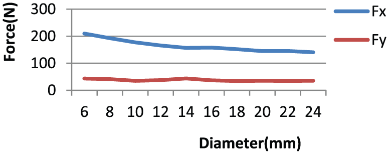
Relationship between milling force and diameter.
In Figure 2, it could be concluded that with the increase in the milling cutter diameter, the tangential force Fx decreases obviously and so does the radial force Fy, but with a small range. And the milling forces fluctuate slightly between 10 and 16 mm. The regression method was applied to fit the relationship between the milling cutter diameter and the tangential force Fx. It could be observed that quadratic polynomial fits well and the result could be expressed as
Blunt radius
The scale of the blunt radius of cutting edge is set between 2.5 and 25 μm and the increase in each scale is 2.5 μm. Figure 3 shows the curves between the blunt radius and the milling force which are obtained by simulation.

Relationship between milling force and blunt radius.
In Figure 3, it could be seen that the milling force and the blunt radius linearly increased. Due to the increase in the radius, the cutting edge of the end mill is no longer sharp. If the blunt radius is greater than the instantaneous uncut chip thickness, the practical rake angle is negative. When the cutter tooth presses and slides along the surface of the workpiece, it causes work-harden and is not conductive to the next cutting process. However, appropriate blunt radius is necessary, for excessively sharp cutting edge can easily lead to edge collapse. As a result of fitting the two curves in Figure 3, the regression equations could be written as
Helix angle
The scale of the helix angle is from 12° to 40° and the increase in each scale is 4°. Figure 4 shows the curves between the helix angle and the milling force which were obtained by simulation.

Relationship between milling force and helix angle.
Figure 4 shows that the milling force and the helix angle are in monotonous relations. The milling force decreases linearly with the increase in helix angle. The results are as follows:
Rake angle
The scale of the rake angle is set from 6° to 26° and the increase of each scale is 2°. Figure 5 shows the curves between the rake angle and milling force which were obtained by simulation.

Relationship between milling force and rake angle.
Figure 5 shows that the rake angle and the milling force do not completely linearly decrease. The tendency of Fy changes when the rake angle reaches 20°–22°, but the increasing amplitude is not large. The reason is that when the rake angle increases, the shear angle increases, the plastic deformation of the metal decreases, the deformation coefficient decreases, and the friction along the rake face decreases, so that the milling force also decreases. However, too large rake angle leads to small wedge angle, the intensity of the tool becomes weaker, it easily causes tipping, and finally, it may affect the life of milling cutter. By linearly fitting the simulation results, it holds that
Relief angle
The scale of the relief angle is set at 2°–16° and the increase in each scale is 2°. Figure 6 shows the curves between the relief angle and the milling force which were obtained by simulation.

Relationship between milling force and relief angle.
Figure 6 shows that with the increase in the relief angle, the milling force changes unstably, but within a small range. So, the effect of relief angle on milling force can be neglected. In practical cutting process, the relief angle of end mill is relative to the anti-vibration problem and the friction force between the rear face and the machined surface. Increasing the relief angle can reduce the contact area between the rear face and the surface of the workpiece. As a result, the friction reduces and the blade becomes sharper, and it does good to improve the tool life. However, an oversize relief angle will lower the pressing of the flank to the workpiece and it is not conductive to the suppression of vibration or flutter in machining process which will lead to poor processing quality.
A novel milling force model of end mill
Empirical model of milling force
According to the research conclusion of metal cutting theory, elastic–plastic deformation and friction condition would be affected by different cutting parameters and tool angles during milling process. They will change the chip-forming process, and thus change the milling force. What mentioned above could reach a conclusion that there is a complex index empirical equation between the cutting forces and the cutting parameters when specific machine tool and cutting tool geometric parameters are decided. The equation can be expressed as follows

where F is the cutting force, k is the coefficient determined by the cutting material and grinding condition, v is the milling speed, ap is the milling depth, fz is the feed, ae is the milling width, and D is the diameter. It could be seen from equation (2) that the relation between the diameter and the milling force was linear, which is not quite accurate.
In order to accurately obtain the coefficients of the empirical model, orthogonal cutting simulation experiments were performed. Five cutting parameters were considered and four levels were set up. The structural parameters of milling cutter were as follows: blunt radius was 0.01 mm, helix angle was 30°, rake angle was 15°, and relief angle was 8°. The milling parameters and simulation results are shown in Table 1.
Milling parameters and simulation results.

The coefficients of the empirical milling force model could be obtained as follows after nonlinear fitting of the above simulation results:

Novel milling force model of end mill
It could be learned from the above analysis that the diameter of end mill, blunt radius, helix angle, and rake angle had significant impact on milling force. Based on the fitting situation between the tool geometric parameters and the milling forces, it could be inferred that their relation might be either linear or quadratic polynomial. Because quadratic polynomial contains linear relation, the quadratic polynomial regression model about the four tool geometric parameters and empirical milling force model were gathered together in order to obtain a milling force model. The new model contains tool geometric parameters and milling parameters, which means that once the new model is established, it is needless to carry out new experiments and calculations to obtain the coefficients of the model but apply directly to this model when tool geometric parameters and milling parameters change. In the empirical model of milling force, the relation between the milling cutter diameter and the milling force was defined as linear which contradicted with the above analysis. Therefore, the diameter was classified as a parameter of quadratic polynomial to establish the new milling force model, and it is expressed as follows

where k1, k2, …, k9 are the impact factors of tool geometric parameter.
In order to accurately obtain the coefficients of the new model, four structure parameters of end mill were set into four levels to carry out the orthogonal experiment simulation analysis. The cutting parameters were as follows: each tooth feed was 0.1 mm, axial cutting depth was 1.5 mm, and radial cutting depth was 1.5 mm. The geometric parameters of end mill and simulation results are shown in Table 2.
Geometric parameters and simulation results.
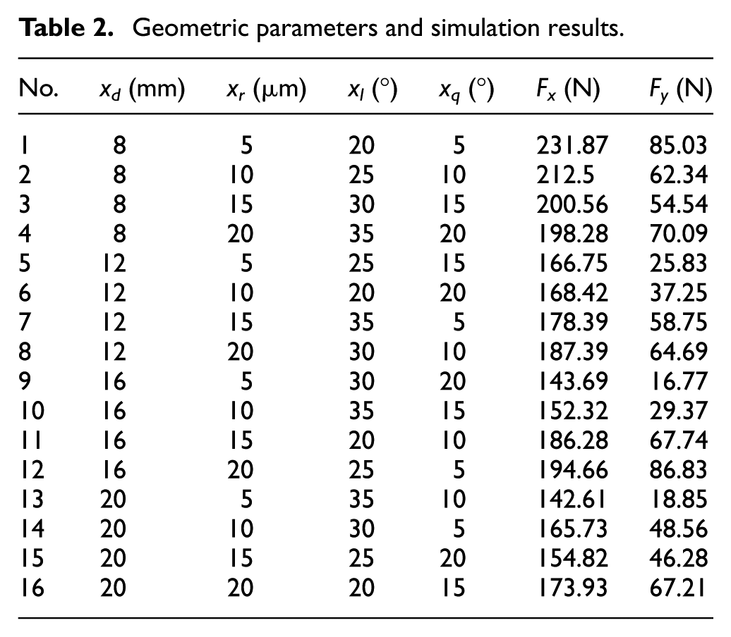
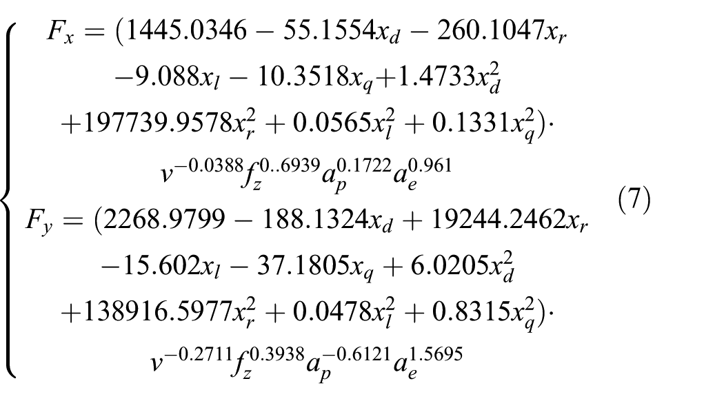
With the method of nonlinear quadratic regression fitting on the results of Table 2, the new milling force model can expressed as

The values of R2 in the X and Y directions were 0.9847 and 0.9512, respectively, which indicated that the new model is good fitting precision. However, the former empirical equation (3) was changed because of the increased geometrical factors of quadratic polynomial and the different relationship of diameter. It means that the fitting precision of equation (5) does not conform to the data of Table 1. In order to obtain high fitting precision of the new milling force model to the data of Tables 1 and 2, the direct method and loop method were adopted to obtain the corresponding coefficients.
Direct method
The data in Tables 1 and 2 were combined to obtain 32 groups of data and the fitting was carried out towards the coefficients of the new milling force model with nonlinear least-squares method. The fitting results are shown as follows

The fitting precisions of Fx and Fy were 0.9197 and 0.7892, respectively, and the fitting precisions were high.
Loop method
First, the empirical equation of milling forces could be inferred from Table 1. Second, the impact factors of tool geometric parameters were fitted according to Table 2 without changing the index coefficient values of milling parameters. Third, new indexes were fitted according to Table 1 without changing the impact factors of tool geometric parameters. After hundreds of times of circulation, the coefficient values would be stable. The final equation of milling force was obtained as follows
After circle fitting, the fitting precisions of Fx and Fy were 0.9771 and 0.9196, respectively. It was obvious that the fitting effect is better to use direct method.
Experimental verification
Simulation experimental verification of the novel model
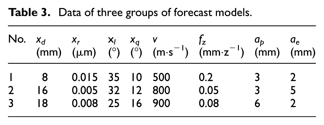
The milling force models which were established by direct method and loop method, respectively, were validated by the following three groups of new parameters as shown in Table 3. By comparing the experimental results and model prediction values, it could be seen from Figures 7 and 8 that the models had good prediction within parameters and the precision of loop method is higher.
Data of three groups of forecast models.
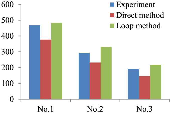
Comparison tangential milling forces.

Comparison radial milling forces.
Processing experimental validation of the novel model
In order to verify the prediction accuracy of the milling force model, nine different geometric parameter carbide cutters which were used for aerospace aluminum alloy 7075 end-milling experiment were grinded. Considering four structural parameters of the milling cutter, three levels were set up as shown in Table 4.
Three levels of the milling cutter geometric parameters.

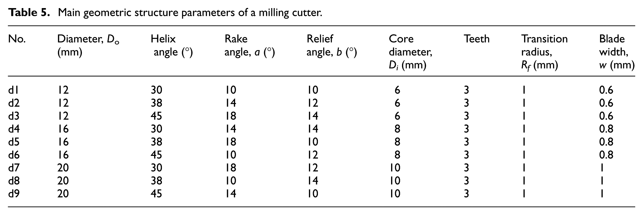
The nine different carbide cutters were named from d1 to d9, and their main geometric parameters are shown in Table 5. Their carbide cutters’ structure model is shown in Figure 9.
Main geometric structure parameters of a milling cutter.

Carbide cutter geometry model.
Under the dry cutting condition of MAZAK UHS FJV-200, aerospace aluminum alloy 7075 was machined with nine different geometry cutters. In the milling test platform shown in Figure 10, data acquisition software DynoWare is used to select milling peak force during the process of stable milling. Milling parameters were as follows: milling speed = 200 m/min, axial cutting depth = 6 mm, radial cutting width = 3 mm, and feed per tooth = 0.05 mm/s. The test results are shown in Table 6.
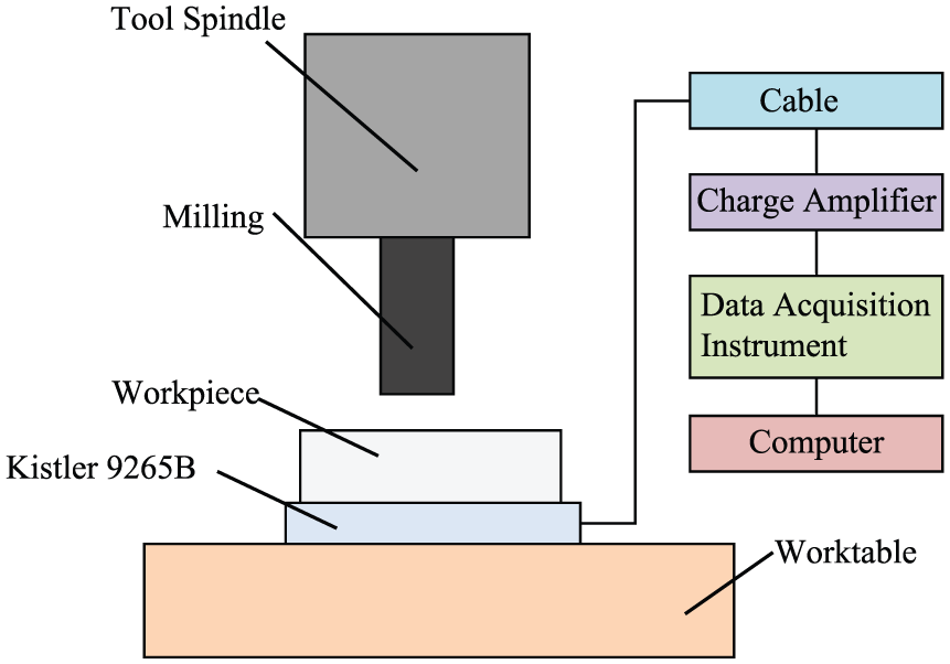
Schematic diagram of milling test.
Milling force values under different rotation speed.

Since the milling force in 2D milling simulation only contains the component force in the X and Y directions, the results did not consider the milling force in the Z direction. The milling force expression is shown as follows

In the same milling condition and the same milling parameters, the results which contain the milling force prediction values and the experimental values are shown in Figure 11.

Comparison of milling forces between experimental values and predicted values.
Conclusion
The following conclusions are drawn:
A 2D simulation model of milling force is established and the equivalent transformation equation of rake and relief angles is given.
At aviation aluminum alloy 7075 milling with a cemented carbide tool, the influence law of geometric parameters of solid carbide end mill on milling force is researched and the corresponding mathematical relationship is established. Besides relief angle, the influence of other geometrical parameters on milling force is obvious.
According to the relationship between tool geometric parameters of end milling and milling force, a new milling force model is established on the basis of empirical model. The diameter is classified as a parameter of quadratic polynomial. The model contains the tool geometric parameters and the milling parameters, which means that it is needless to carry out new experiments and calculations to obtain the coefficients of the model. When tool geometric parameters and milling parameters change, it is just applied directly to this model.
By simulation experimental verification, the accuracy of milling force model established by the loop method is higher than that established by the direct method.
Through the milling test, the proposed new model has better prediction accuracy.
The new modeling method can be extended to milling force modeling of other types of cutter.
Footnotes
Handling Editor: Jining Sun
Declaration of conflicting interests
The author(s) declared no potential conflicts of interest with respect to the research, authorship, and/or publication of this article.
Funding
The author(s) disclosed receipt of the following financial support for the research, authorship, and/or publication of this article: This work was supported by National Natural Science Foundation of China (Nos.51605337,51505338), the Zhejiang Provincial Natural Science Foundation of China (Nos.LQ17E050003, LQ16E050004).