
Abstract
High efficiency and high precision milling, as the eternal goal of CNC machining, needs to balance many constraints for selecting the most reasonable processing parameters. This paper presents an efficient machining parameter optimization method for finishing milling operation with multiple constraints. Firstly, under the multiple constraints of parameter feasible region, milling force, milling stability, roughness, and machining contour accuracy, a multi-variable parameter optimization model with machining efficiency as the objective is established. A four level cycle optimization strategy has been detailly described for solving the optimization problem, in which the feed per tooth is optimized by using the golden section method, and with the aid of the random vector search method, the spindle speed, radial, and axial depth cuts are both numerically iterated. The optimal machining parameter combination of the tooth number, feed per tooth, spindle speed, radial, and axial depth of cuts are achieved at last. Finally, the experimental verification results show that the proposed method can greatly improve the machining efficiency under chatter free condition and achieve an efficient finishing milling with consideration of the multiple constraints.
Introduction
The goal of CNC machining is to achieve high efficiency and high precision, that is, to maximize the material removal rate (MRR) under the premise of ensuring machining quality and other constraints. In the traditional methods, operators mostly do repeated experiments and use manual experience as the basis reference to select the machining parameters. Unfortunately, this approach is always time-consuming and uneconomical, and the selected parameters are mostly conservative, thus making it difficult to achieve a real high efficiency machining. 1 There is no doubt that increasing machining parameters is the most effective way to improve the processing efficiency. However, it is easily prone to generate milling vibrations and chatter, 2 even damage the machine and tools, and deteriorate the machining quality of parts. Therefore, an effective method is in urgent need of research to guide the selection of reasonable machining parameters for high efficiency and high precision.
In order to improve the MRR, many scholars have studied the parameter optimization problem taking surface roughness into account. Onwubolu 3 presented a new methodology to use the roughness as the one of bounds for the autonomous selection of cutting conditions in milling operations by using Tribes. Nair et al. 4 took surface roughness and MRR as the optimization targets, and systematically analyzed the experimental data. They found that when the roughness evaluation characteristics are selected differently, the results obtained by the four different optimization methods are not the same, which indicated that the optimization need to consider the influence of the parameter levels. Zerti et al. 5 analyzed the influence of different machining parameters on roughness, cutting force, and MRR in dry turning process, then established four optimization goals, such as quality, efficiency, energy consumption, and cutting force, and further obtained the optimal parameters by using neural networks. It is expected that the roughness is mainly affected by the feed speed. Qu et al. 6 studied the parameter optimization problem in thin-walled part milling process, and established the multi-objective optimization problem with three contradictory goals, including roughness, milling force, and MRR, lastly obtained the optimal parameter combination of spindle speed, feed per tooth, and axial depth of cut. Tebassi et al. 7 experimentally investigated the influence of cutting parameters on roughness, cutting force, machining efficiency, and energy consumption during the turning process, and proposed a multi-objective optimization method to obtain the smallest roughness, cutting force and machining efficiency, and maximum MRR. Dikshit et al. 8 carried out a mathematical model of surface roughness for milling process in terms of feed per tooth, cutting speed, axial, and radial depth of cuts. Here, a second-order full quadratic model was developed and the optimization using the teaching-learning-based methodology could take minimum effort and provide better results.
At the same time, obtaining high MRR has also been deeply studied by scholars in the case of ensuring the contour precision of machined surface, which is mainly affected by the vibration of the tool and workpiece during cutting process. Budak and Tekeli 9 studied the optimal selection method for the combination of radial and axial depth of cuts under stable milling condition. In the given analysis case, the milling time was reduced about 40%. Kurdi 10 carried out a multi-objective optimization problem with milling stability and surface location error as the objective function. When calculating the surface location error, a certain disturbance amount of the spindle speed was introduced to avoid the rapid change on the surface location error caused by the resonance region, and the robustness of the optimization model was enhanced. Based on the analysis of milling stability and surface location error, Insperger et al. 11 discussed a method to optimize the spindle speed when the radial and axial depth of cuts were determined. The study pointed out that the optimal spindle speed was selected from the left side of the resonance zone, which provided an enlightening idea for the optimization of machining parameters. Based on milling dynamics, Merdol and Altintas 12 divided the milling parameter optimization into two steps. Firstly, the spindle speed, radial, and axial depth of cuts were selected with consideration of milling stability, torque, and power limits. Secondly, the milling force, milling stability, torque, and power were checked along the whole path after generating the NC program and the feed speed and spindle speed were adjusted to avoid overruns. Wan et al. 13 proposed a parameter optimization method to ensure the surface dimensional accuracy based on statics analysis, in which the linear relationship between surface error and feed per tooth and radial depth of cut was established. Zhang and Ding 14 put forward a chatter free milling parameter optimization method, in which the tool vibration displacement was minimized and the MRR was maximized by optimizing the spindle speed and axial depth of cut. Hu et al. 15 constructed an objective function based on MRR and tool life, and proposed a milling parameter optimization model under the constraint of cutting stability. The expected value of MRR and tool life were used in the optimization model to realize the quantitative adjustment of the optimization parameters and the effective control of the optimization direction. Li et al. 16 optimized the milling parameters based on the dynamic displacement response for a ruled surface impeller machining. In the method, the machining parameters and maximum dynamic displacement of the cutter were used as training samples to train the BP neural network, and the maximum dynamic displacement of the cutter was taken as the optimization objective. Mokhtari et al. 17 improved the micro-milling tool geometry to find the maximum allowable cutting depth for the chatter-free machining, in which the objective function was defined as the maximization of the minimal cutting depth within the stability lobe diagram.
For the thin-walled part milling, Alan et al. 18 studied the variation of dynamic stiffness and milling stability of the parts due to material removal, and selected the axial depth of cut under its critical limits for improving the machining efficiency. Budak et al. 19 built up a prediction method of time-varying dynamics as the margin was removed layer by layer after in five-axis milling of blade parts, then established a milling stability domain diagram that changes with the cutting position, lastly by which a more reasonable spindle speed and axial depth of cut were selected. Germashev et al. 20 analyzed the vibration response of the flexible thin-walled parts during the milling process and found that the dynamic action between the force and workpiece would be different at various spindle speeds, and a better spindle speed was selected by considering the vibration amplitude of workpiece. Recently, Ringgaard et al. 21 presented an optimization method to maximize the MRR without violating forced vibration and chatter stability constraints. The cost function was formulated using penalty terms which penalized the function as chatter and forced vibration constraints. At last, the optimal spindle speed, feed per tooth, and axial depth of cut were achieved in milling of thin-walled structures.
The above literature reviews show that although lots of research have been focused on the machining parameter optimization by many scholars, there are still some shortcomings in these existing methods. Firstly, some research does not consider the physical dynamics properties of the machining system, especially the dynamical engagement characteristics between the cutter and workpiece, including milling stability and machining accuracy. Secondly, only part of machining parameters, such as spindle speed and axial depth of cut, can be optimized, and other important machining parameters are ignored, which thus limits the applicability of these method. In machining process, the typical machining parameters have spindle speed, radial depth of cut, axial depth of cut, feed per tooth, and cutter tooth number, etc. Meanwhile, the constraints are multiple, such as milling stability, profile accuracy, and roughness of machined surface, etc. Hence, how to obtain the maximum machining efficiency under so many complex constraints is a difficult challenge. The purpose of this paper is to propose a reasonable and effective milling parameter optimization method under chatter free condition by establishing and solving a single objective, multiple constraints, and multiple variables problem. The structure of this paper is organized as follows: in Section 2, considering the physical constraints of the machining system, the mathematical model of the optimization problem is established; in Section 3, the algorithm for solving the optimization model is given; in Section 4, the experimental verification is carried out, and finally the conclusion of this paper is summarized.
Mathematical model of the optimization problem
Optimization objective
Figure 1 shows a typical finishing milling process. The thickness of the finishing allowance is usually small in the normal direction of the part surface. According to the distribution of the allowance, two kinds of tool path topology are usually used to remove it: depth-first and width-first. The goal of parameter optimization is to maximize the machining efficiency under the relevant constraints. Generally, in the condition of constant cutting parameters, the milling machining efficiency can be expressed by the MRR as following.

Where Nt is the cutter tooth number. ft is the feed per tooth (mm/tooth). n is the spindle speed (rpm). ae is the radial depth of cut (mm). ap is the axial depth of cut (mm).
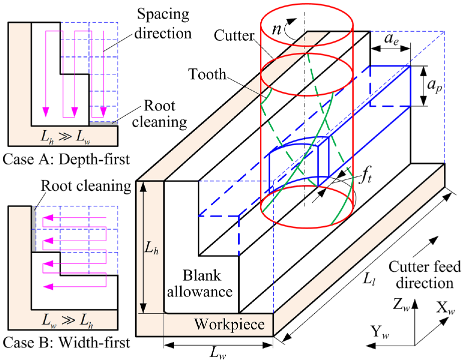
Schematic diagram of finishing milling process.
Optimization variables
It can be seen from the above formula that the optimization objective function includes five variable parameters, such as tooth number and other four basic cutting parameters (spindle speed, radial depth of cut, axial depth of cut, and feed per tooth). Thus, in this paper, the optimization variable is defined as
Multiple constraints
The selection of milling parameters would be restricted by many factors, such as the feasible region of machining parameters, cutting force, milling stability, workpiece contour accuracy, and roughness of machined surface. The quantitative model of these constraints will be established step by step in the following.
Parameter feasible region constraint
During the actual machining process, the determination of optimization variable will consider multiple constraints, in which the first one is the limitation of the optional range of parameters. Considering the machining ability of spindle and cutter, there exist some upper or lower limits for the selection of spindle speed, radial and axial depth of cuts, and feed per tooth. For instance, the spindle speed should be less than or equal to its maximum allowable value, the radial depth of cut should not exceed the cutter diameter, the axial depth of cut should be less than the length of cutting edge of cutter, the selection of feed per tooth needs to take the cutting ability of cutter into account, and the choose of tooth number should ensure the chip removal ability of cutter. In summary, the feasible region of parameter selection can be formed, which is also the most basic constraint for the optimization variable, as shown in the following formula.
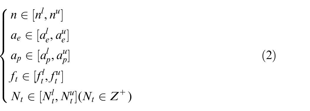
Where the superscript u denotes the upper limit. The Superscript l denotes the lower limit.
In addition, when choosing the depth-first tool path topology, the line spacing in width direction should be uniform. While the line spacing in axial direction should be equispaced under the width-first milling situation. Hence, one can further obtain:

Where
Milling force constraint
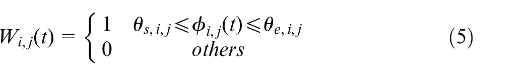
During machining process, milling force will be produced when the cutter and workpiece are engaging dynamically with each other. Excessive milling force will induce cutter deflection, cause impact, and even tool breakage. Therefore, it is necessary to restrict the milling force. As shown in Figure 2, according to the basic cutting force mechanism model, the tangential, radial, and axial cutting forces of the cutting point P of the ith tooth on the jth cutting unit at an arbitrarily rotation angle
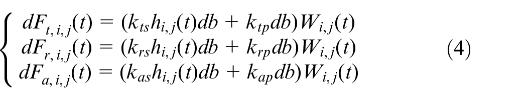
Where
Where
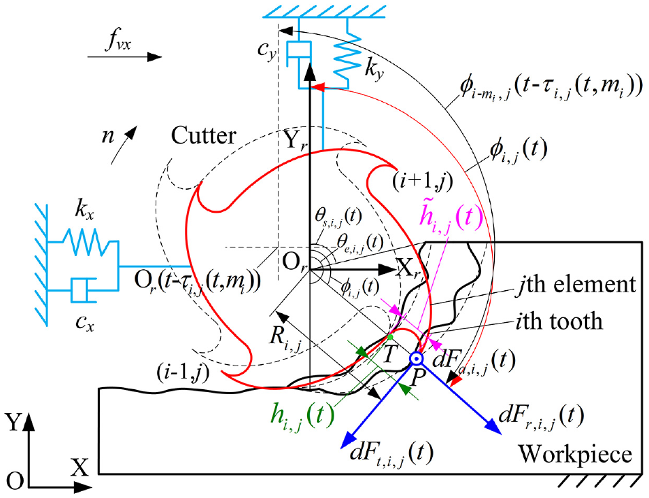
Milling mechanics and dynamics model.
In equation (4), the instantaneous uncut chip thickness
Where
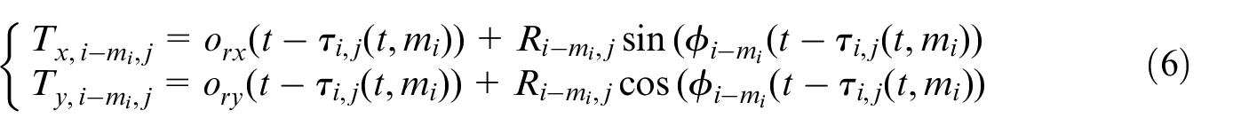
At the same time, the point T can also be derived by
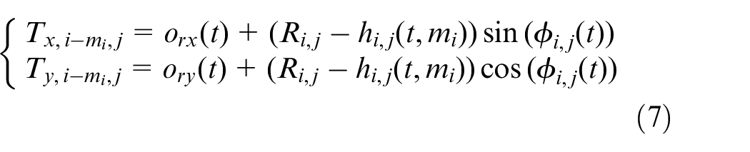
Based on the cutter feed motion relationship, where the dynamic displacement response of the cutter is ignored, one can achieve
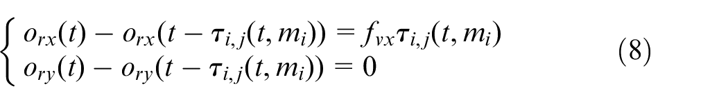
Where
Combining the above three equations, the delay time term can be derived as
Where
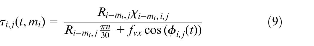
Furthermore, the available instantaneous uncut chip thickness can be obtained by
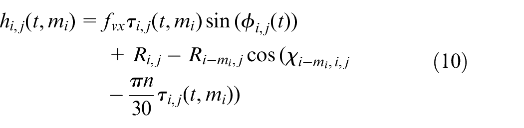
Then, the actual instantaneous uncut chip thickness is the minimum of all available chip thickness greater than zero, which can be mathematically expressed as

Finally, substituting equation (11) into (4), the cutting forces generated by all the cutting units participating in the cutting at the same time are summed in the range of effective cutting depth, and the total cutting force acting on the cutter is
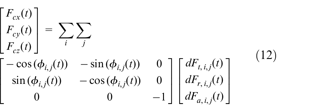
In this case, the resultant cutting force acting on the cutter is
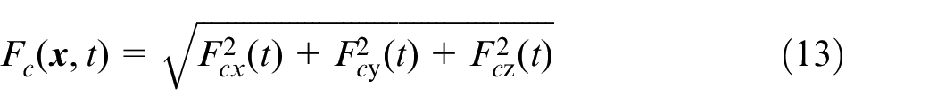
Considering the impact resistance of the cutter, the maximum milling force should be limited within a certain range as following.

Where
Milling stability constraint
In order to ensure the milling process in a stable state, it is necessary to consider the constraint of milling chatter, which often restricts the upper limit of milling parameter selection.
As shown in Figure 4, milling chatter is mainly caused by the regeneration mechanism of the flexible machining system. Considering the regenerative effect induced by the flexible cutter system in milling process, the transient chip thickness can be obtained as follows.

Next, the milling dynamics model can be established by
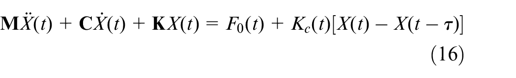
Where

Then, the system dynamics equation can be further written as following state space model.

Where
In this paper, the idea of the SDM
22
is used to solve the above equation for stability prediction. Now, the cutter rotation period is needed to be discretized into a time series with a small equal interval of
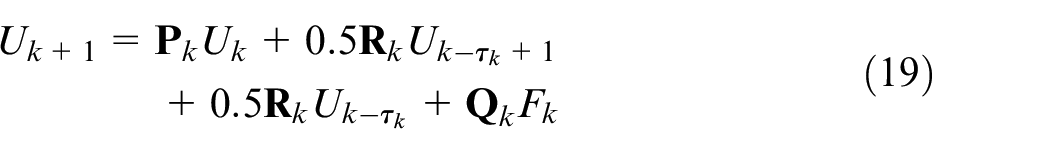
Where
Here, the above equation can be further transformed into a discrete map, as shown below.

Where
The state transition relationship of the system in one cutter rotation period can be expressed as

Where
According to the Floquet theory, the system is stable only if the modulus of all eigenvalues of the state transformation matrix is less than or equal to one. Hence, the constraint of milling stability can be expressed as

Where
Machining quality constraint
When the milling process is stable, the dynamical response of the cutter can be obtained by calculating the system fixed point. Let

In this case, the transient displacement response of the cutter can be substituted into the following equation to obtain the instantaneous trajectory surface of the cutting point P.
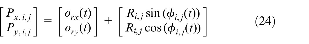
Where
As shown in Figure 3, the machined surface contour
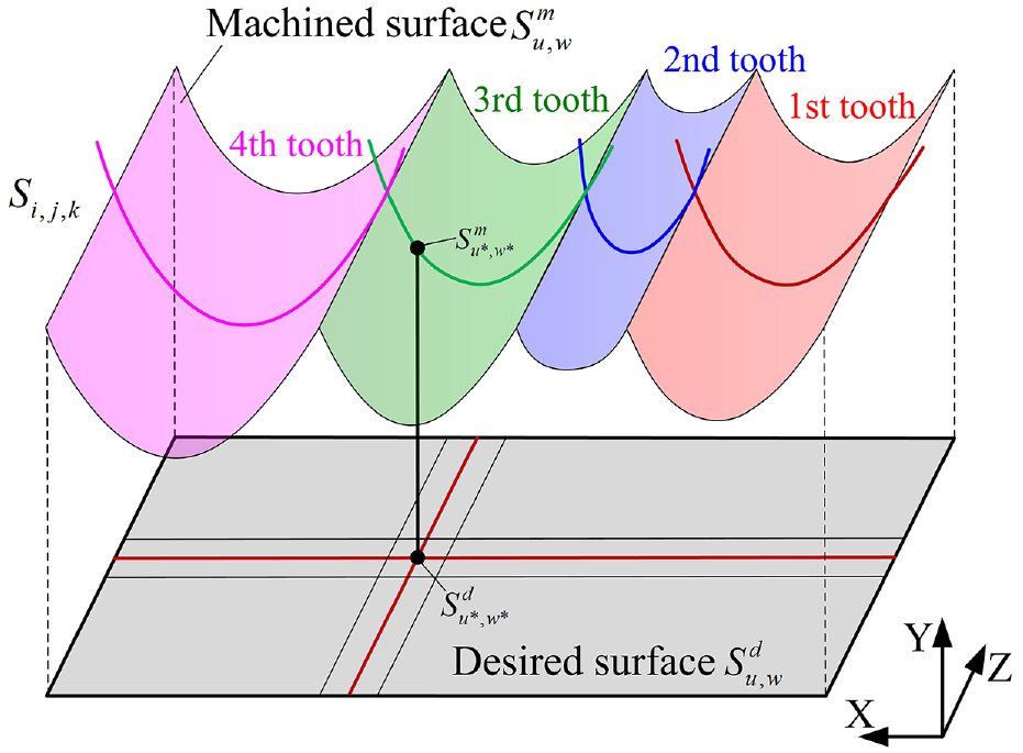
Definition diagram of the machining quality constraint.
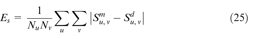
The constraint condition of the surface contour error can be achieved as

Where
Then, the roughness would be calculated by
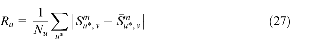
Correspondingly, the constraint condition of the roughness is defined as

Where
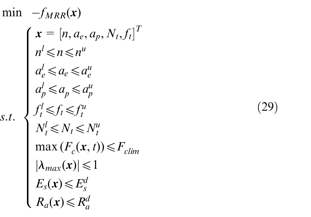
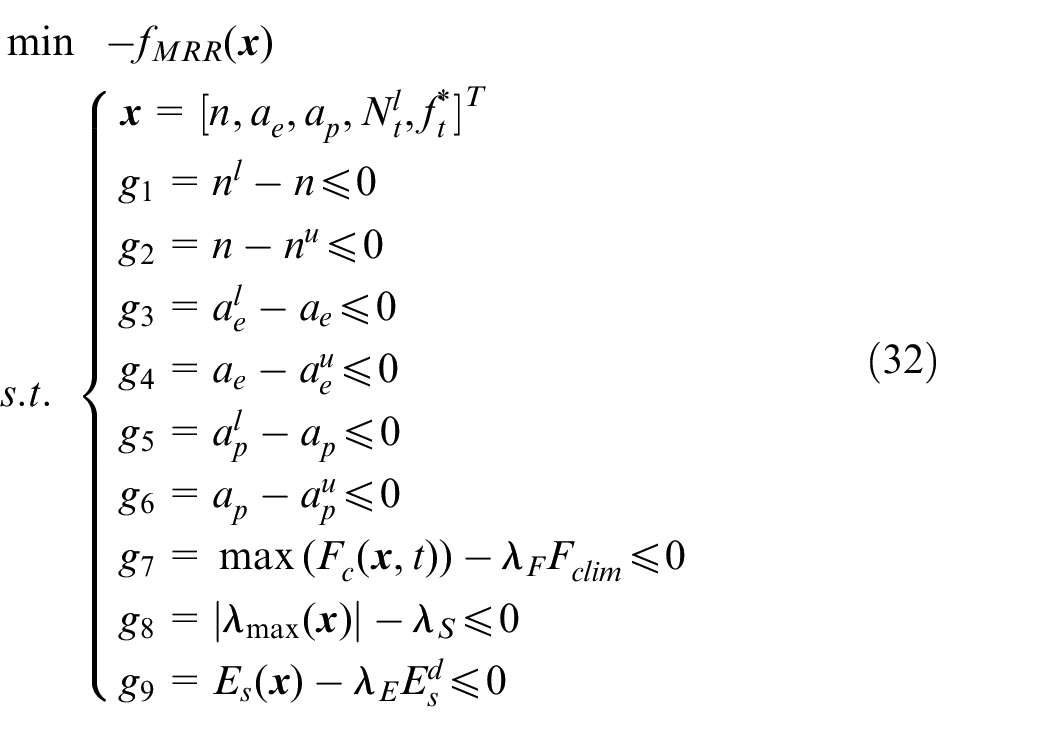
Mathematical model of the optimization problem
Finally, considering all above multiple constraints together, the mathematical model of the machining parameter optimization problem can be formed. It becomes
Solution of the optimization model
Uncertainty treatment of model parameters
Because there is a certain degree of uncertainty for the model parameters of the actual dynamic system, which will cause some deviation of the constraint critical value between the actual condition and the real one. Therefore, it is necessary to give a certain safety margin to the constraint conditions. At this time, the above formula is improved into
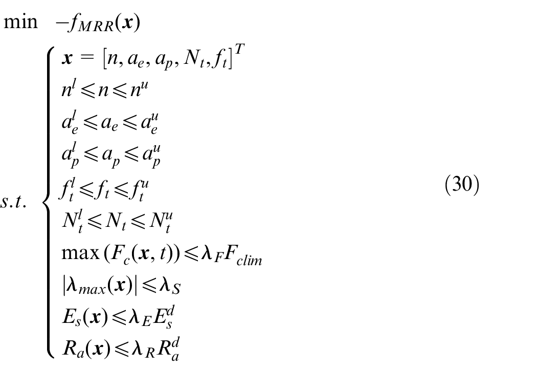
Where
ft Optimization based on the golden section method
According to the prior knowledge, the roughness of milling machined surface is closely related to the feed per tooth, and is less affected by other machining parameters. Consequently, in order to improve the machining efficiency, it is often expected to increase the feed per tooth as much as possible on the premise of satisfying the roughness constraint. The roughness constraint can be dropped mathematically from equation (30) as following.

It can be judged that the above function is convex, and its solving can be applied by the golden section method. The optimization procedure is as follows:
Step (1): Initialize the optimization variable
Step (2): Calculate
Step (3): Let
Step (4): If satisfying
[n,ae,ap]T Optimization based on the random vector search method
After the
In order to solve the multiple constraints optimization problem, the random vector search method is employed here. As shown in Figure 4, the basic idea of this method is to generate multiple initial samples randomly in the feasible region, then for the sth sample
Step (1): Determine the optimization objective function
Step (2): Extract the sth sample
Step (3): Further extract the kth variable
Step (4): On its qth search, generate a random vector as following.
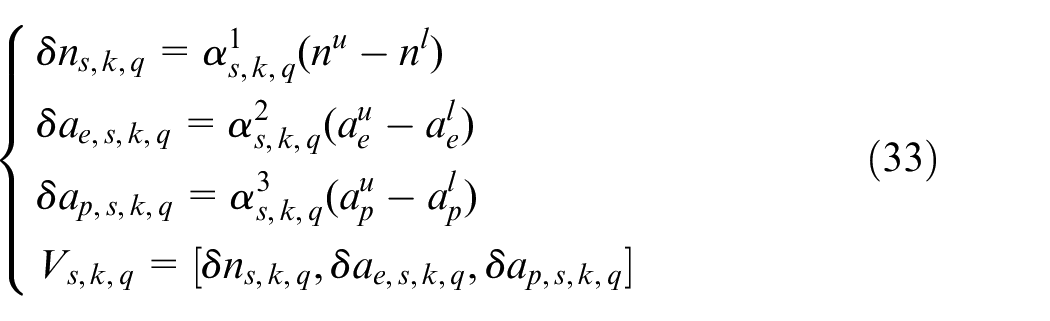
Where
Step (5): Calculate the (k+1)th value of the sample
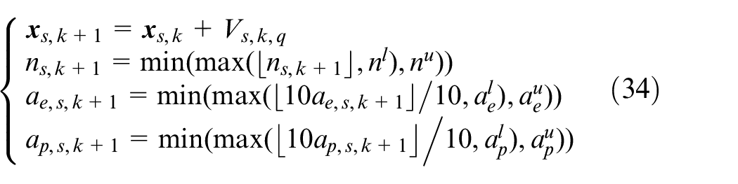
Where ⌊⌋ is the rounding down operation. After this operation, one can make sure that the spindle speed is integer, and both the radial and axial depth of cuts have only one decimal.
Step (6): Substitute the obtained parameters
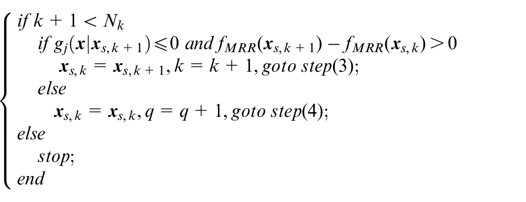
Then, one can obtain the optimal result
Step (7): Let
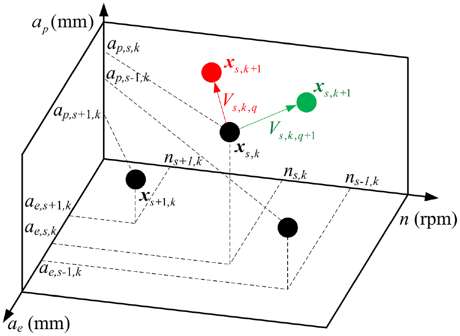
Schematic diagram of random vector search.
Overall optimization procedure
Figure 5 summarizes the overall optimization flowchart. At the beginning of optimization, the tool geometry parameters, dynamics parameters, cutter runout, and specific cutting force coefficient are initialized, and the depth-first or width-first tool path topology is selected. Later, the machining parameters are optimized in a four layer cycle iteration. The first layer is to optimize the discrete number of allowance under depth-first or width-first situation. The second layer is to optimize the tooth number of cutter. The third layer is to optimize the feed per tooth by using the golden section method. The fourth layer is to optimize the spindle speed, radial, and axial depth of cuts combination with the aid of the random vector search method. After the four layer iteration calculation, the machining parameters with the maximum milling efficiency are selected as the optimal results.
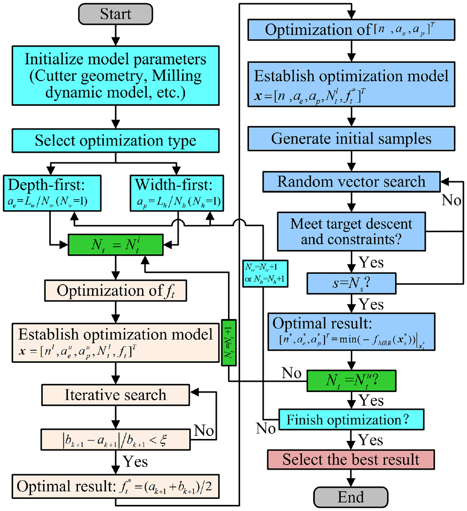
Overall optimization flowchart.
Experimental verification
Experimental setup
In order to verify the validity of the proposed machining parameter optimization method, the paper firstly carried out a few parameter optimization cases that performed under the given boundary conditions, then conducted a series of milling experiments on the five-axis high-speed machining center DMG DMU50 to verify the theoretical analysis results. As shown in Figure 6, the workpiece material was aluminum alloy 7050 with a machining allowance of Lw = 3 mm, Lh = 50 mm, and Ll = 110 mm. The machining tool path topology was selected as depth-first. In the tests, a series of cutters with different tooth number, a diameter of 16 mm, a helix angle of 45°, and an overhung length of 85 mm were employed. The cutter had runout with offset value 8 µm and its angle 25.6°, and inclination value 1.1 × 10⁻⁴° and its angle 46.5°. The milling process had no coolant, and the specific cutting force coefficients of the cutter-workpiece combination were calibrated as kts = 999 N/mm2, krs = 327 N/mm2, kas = 357 N/mm2, ktp = 30 N/mm, krp = 32 N/mm, kap = 0.4 N/mm. Along the X and Y directions in machining coordinate system, the modal masses of the tool tip were set as 0.407 and 0.655 kg, the damping ratios were set as 0.035 and 0.028, and the natural frequencies were set as 959.4 and 922.1 Hz, respectively, through the modal impacting and identification experiment. During the milling process, the transient cutting force signal had been measured by a 9265B Kistler dynamometer with a sampling frequency of 10 kHz. After machining, the Taylor Hobson aspheric profile tester was used to measure the surface roughness topography of the machined surface with a resolution of 0.125 µm, and the global classic SR575 three-coordinate measuring machine was used to test the contour accuracy of the part with a resolution of 1.8 µm.
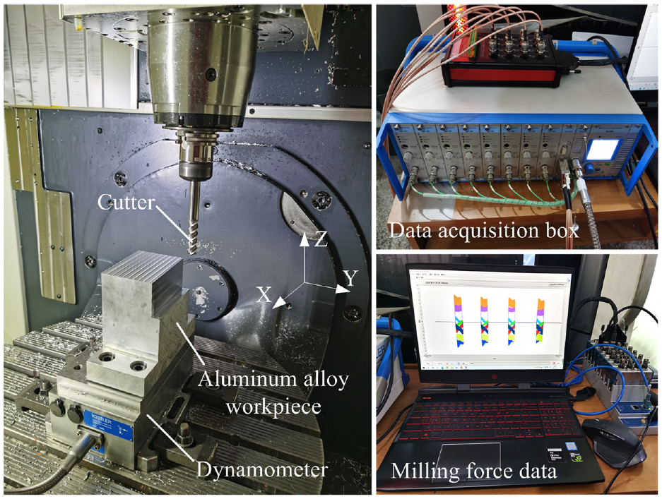
Experimental setup.
Verification cases
In terms of the constraints, the parameter feasible region of cutter tooth is set as
In the total optimization procedure, the feed per tooth is firstly optimized under the constraint of roughness, and it can be concluded that the optimal feed per tooth for the single-tooth cutter, two-tooth cutter, three-tooth cutter, and four-tooth cutter are 0.275, 0.15, 0.10, 0.075 mm/tooth, respectively. Then, the optimization of other milling parameters for the cutters with different tooth number are further performed. Figure 7 demonstrates the MRR iteration process of all samples under different tooth numbers and radial depth of cuts. Among them, Figure 7(a)–(d) are the MRR variation trend of all 30 samples in total 60 iteration steps for the single-tooth, two-tooth, three-tooth, and four-tooth cutter with a radial depth of cut of 3 mm (Nw = 1), respectively. Figure 7(e) and (f) are the MRR variation trend of all 30 samples in total 60 iteration steps for the three-tooth cutter with a radial depth of cut of 1 mm (Nw = 3) and 1.5 mm (Nw = 2), respectively. As can be seen that the MRR of all samples keeps increasing during the iteration process. After the iteration completed, the MRR of the 28th individual of the three-tooth cutter with a radial depth of cut 3 mm (Nw = 1) in Figure 7(c) reaches to the global maximum value, which is equal to 131.2 cm3/min. It shows that this individual is the best individual of all samples. From the comparison between Figure 7(c) and (d), one can still realize that more tooth number may not obtain a higher machining efficiency, especially under the multiple constraint conditions.
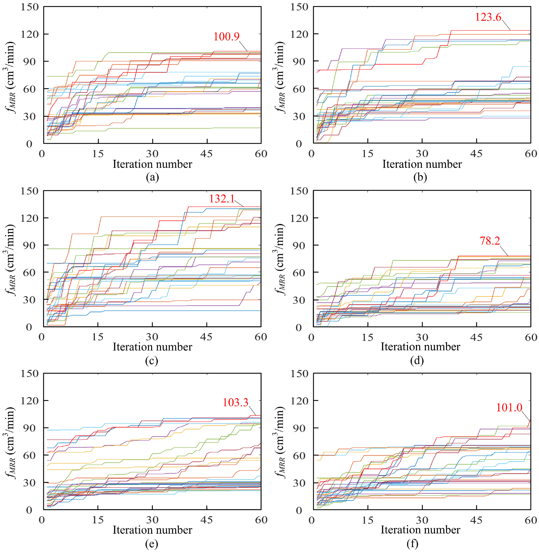
MRR iteration process of all samples under different tooth numbers and radial depth of cuts: (a) MRR iteration result (Nt = 1, ae = 3 mm), (b) MRR iteration result (Nt = 2, ae = 3 mm), (c) MRR iteration result (Nt = 3, ae = 3 mm), (d) MRR iteration result (Nt = 4, ae = 3 mm), (e) MRR iteration result (Nt = 3, ae = 1 mm), and (f) MRR iteration result (Nt = 3, ae = 1.5 mm).
Figure 8 detailly illustrates the evolution process of the above optimal individual in the whole iteration calculation. Among them, Figure 8(a) shows the initial and final spindle speed and axial depth of cut values of the total 30 samples, as well as its iterative values of the 28th individual. It is obvious that all samples are satisfied the requirement of milling stability. Besides, the distribution of the samples before optimization is scattered, while has a stronger aggregation after optimizing. Figure 8(b) further plots the variation of spindle speed and axial depth of cut of the 28th individual during total iteration, and the optimized spindle speed and axial depth of cut are obtained as 9411 rpm and 15.6 mm, respectively. Besides, Figure 8(c)–(e) show the variation of the machining contour error, maximum milling force, and maximum eigenvalue of the milling stability transfer matrix with the iteration number of the 28th individual. What we can see more is that the above three physical parameters always satisfy its corresponding constraint conditions. The machining contour error is very close to its allowance value in Figure 8(e), which indicates that the optimization iteration has well been done. Figure 8(f) compares the change of MRR before and after optimization. Among them, the average MRR of all samples after optimization has increased by 216.7% compared to that of before optimization, and the maximum MRR of all samples after optimization has increased about 53.6% than before. More importantly, the optimized MRR of the best individual is 659.2% higher than that of initial, indicating that the parameter optimization process can greatly improve the machining efficiency.
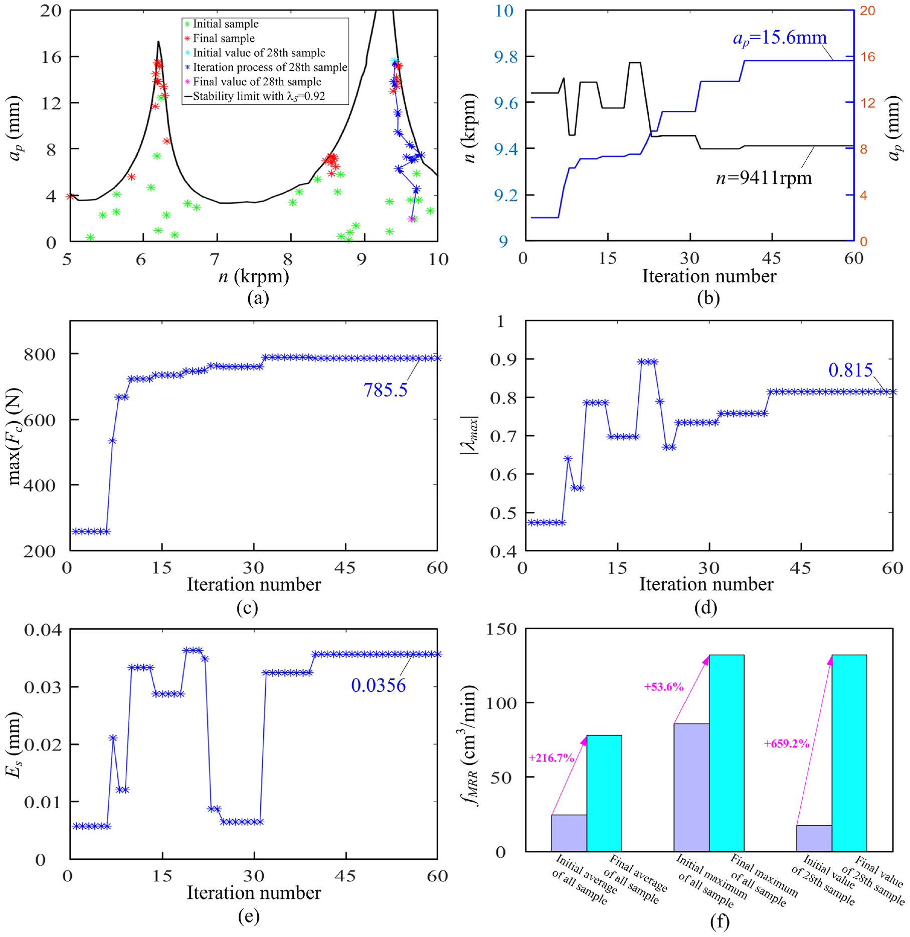
Evolution process of the optimal individual parameters: (a) iteration result of n and ap, (b) iteration process of n and ap, (c) iteration process of max(Fc), (d) iteration process of λmax, (e) iteration process of Es, and (f) MRR comparison.
The paper makes further efforts on the milling experiments by using the optimal machining parameters
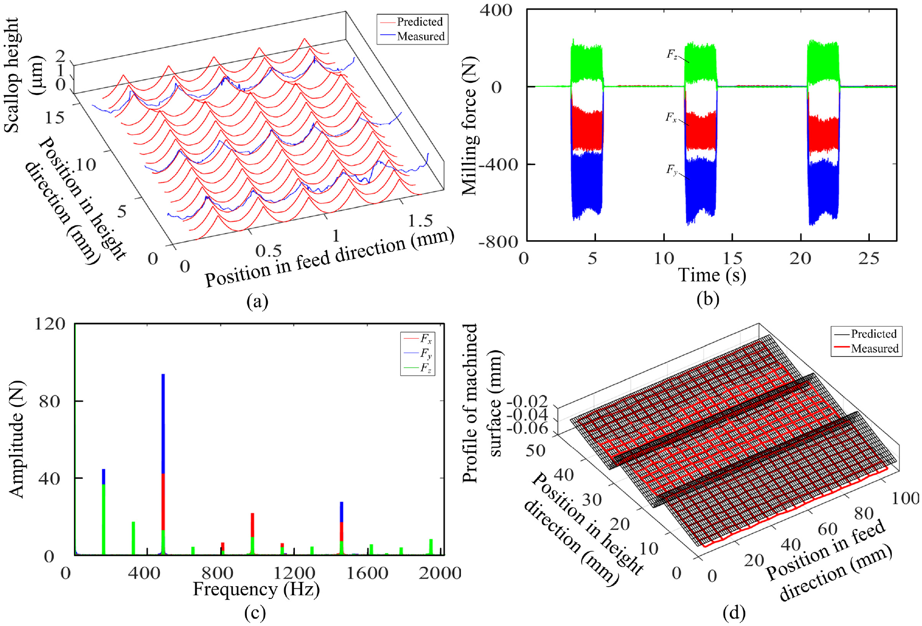
Measured values of the optimal individual parameters: (a) roughness comparison, (b) measured milling force, (c) frequency spectrum of milling force, and (d) machining error comparison.
Conclusion
In this paper, an efficient parameter optimization method for finish milling machining with chatter free has been proposed. Through the theoretical research and experimental verification, the results show that the method can greatly improve the milling efficiency and realize chatter free finish machining under multiple constraints. In the optimization model, multiple constraints such as parameter feasible region, milling force, milling stability, machining contour accuracy, and roughness are considered, and multiple variables such as tooth number, feed per tooth, spindle speed, radial, and axial depth of cuts are both studied. Concerning the uncertainty of model parameters, safety margin coefficients are used to enhance the adaptability of the model. As the roughness is mainly affected by the feed per tooth, it is proposed to use the golden section method to solve the single variable optimization problem. Furthermore, when solving the optimization problem with the remaining variables, a numerical random vector search optimization method is proposed, which can ensure a fast iteration and realize multi-variable optimization of spindle speed, radial, and axial depth of cuts. Based on the proposed four level cycle optimization strategy, the paper can determine the optimal individual in all samples and select the machining parameter combination with highest efficiency at last.
Footnotes
Declaration of conflicting interests
The author(s) declared no potential conflicts of interest with respect to the research, authorship, and/or publication of this article.
Funding
The author(s) disclosed receipt of the following financial support for the research, authorship, and/or publication of this article: This work was financially supported the National Natural Science Foundation of China (No. 51905410), and the Major Science and Technology Project of Shaanxi Province (No. 2019zdzx01-01-02), the China Postdoctoral Science Foundation (No. BX20180253, 219945), and the Fundamental Research Funds for the Central Universities (No. xzy012019009, xxj022019025).