
Abstract
This article shall explore the characteristics of hydro-mechanical transmission in power shift. Based on the double brakes overlapping, the adjustment of the displacement ratio of variable-displacement hydraulic component is considered, and then a new full power shift method is proposed. Models respectively for speed, torque, and power in the power shift process are built. The ideal power shift timing is deduced, with the ratio between speed of fixed-displacement hydraulic component and input speed being the criterion. By combining theoretical analysis and experimental studies, it shows that in power shift process by regulating the displacement ratio of variable-displacement hydraulic component, the interchange between high- and low-pressure sides in closed hydraulic circuit can be completed, and power transition can be thus realized. A new full power shift method is put forward, in which the shift process is divided into five stages: current range, prior stable stage, power transition stage, post stable stage, and target range. Experiments on full power shift process prove that the full power shift method is not only feasible but also can remove the rotational speed fluctuation in power shift process and realize normal full power transmission of output power.
Keywords
Introduction
Hydro-mechanical variable transmission (HMT) is a kind of double power flow transmission system constituted by hydraulic branch and mechanical branch in parallel. 1 The rotational speed of fixed-displacement hydraulic component in hydraulic transmission unit attains variable changes with the adjustment of displacement ratio of variable-displacement hydraulic component (displacement ratio for short) and achieves stepless speed changing in range after converging speed with the mechanical transmission component. Several ranges are engaged so as to constitute the wide range variable transmission.2,3 The hydraulic transmission unit only transmits power partially, so HMT is more efficient. Because of its ability to achieve high-power stepless speed changing and high transmission efficiency, HMT is applicable to high-power vehicles.
Theories on HMT scheme design have basically matured through years of research. Sung and Kim 4 and Linares et al. 5 proposed a systematic design approach for a three-shaft HMT. The power and speed characteristics were investigated for 12 configurations of the three-shaft HMT using network analysis. 6 Xu et al. 7 developed a HMT for tractors, which improved productivity and fuel economy. Rossetti and Macor8,9 treated the design of a HMT as a multi-objective optimization problem and got a good performance.
Regarding to HMT control, various achievements have been obtained by many scholars in fields of in-range speed ratio follow-up and integrated control strategy. Wei et al. 10 and Yuan et al. 11 studied speed ratio follow-up control and designed a variable parameter proportional–integral–derivative (PID) controller on HMT, which can make the engine work in the most powerful or the most economical mode. Tanelli et al. 12 designed a transmission controller for power shift agricultural tractors, involved with the correct management of clutches. Yang et al. 13 proposed an integrated control strategy of HMT, consisting of speed control strategy in range, range shift conditions, range shift logic and range shift control strategies.
However, in general power shift, the target range clutches would be engaged after the current range clutches are disengaged, which would cause a transitory output power interruption. In the shift process, there are load reversal in hydraulic transmission unit, power flow reversal in hydraulic branch, and function interchanges in hydraulic components. Simultaneously, high and low pressure sides in hydraulic circuit interchange, as a result of which the speed of fixed-displacement hydraulic component changes abruptly, causing the fluctuation of output speed as well as vibrations and noises.
Based on the flexible hydraulic unit of HMT, Hu et al. 14 explored the feasibility of running in the stage of dual range, which provided a new solution to shift without power interruption. But in the study by Hu et al., 14 the displacement ratio kept a constant value. That is to say, when the double brakes overlap, the effect of the adjustment of displacement ratio on the characteristics of HMT in power shift was not taken into consideration. First, based on the double brakes overlapping, the characteristics of HMT in power shift at different displacement ratios are analyzed in this article, by combining theoretical analysis with experiment studies. Then, for the first time, the displacement ratio is regulated in the double brakes overlap, and a new full power shift method of HMT is proposed. Finally, tests on full power shift are carried out. In the full power shift, the interchange between high and low pressures in closed hydraulic circuit is actively controlled, and the power transition is completed during the double brakes overlapping. In the power shift process, output power can be transmitted normally in full power.
Characteristics of rotational speed in power shift process
Power shift method of hydro-mechanical transmission
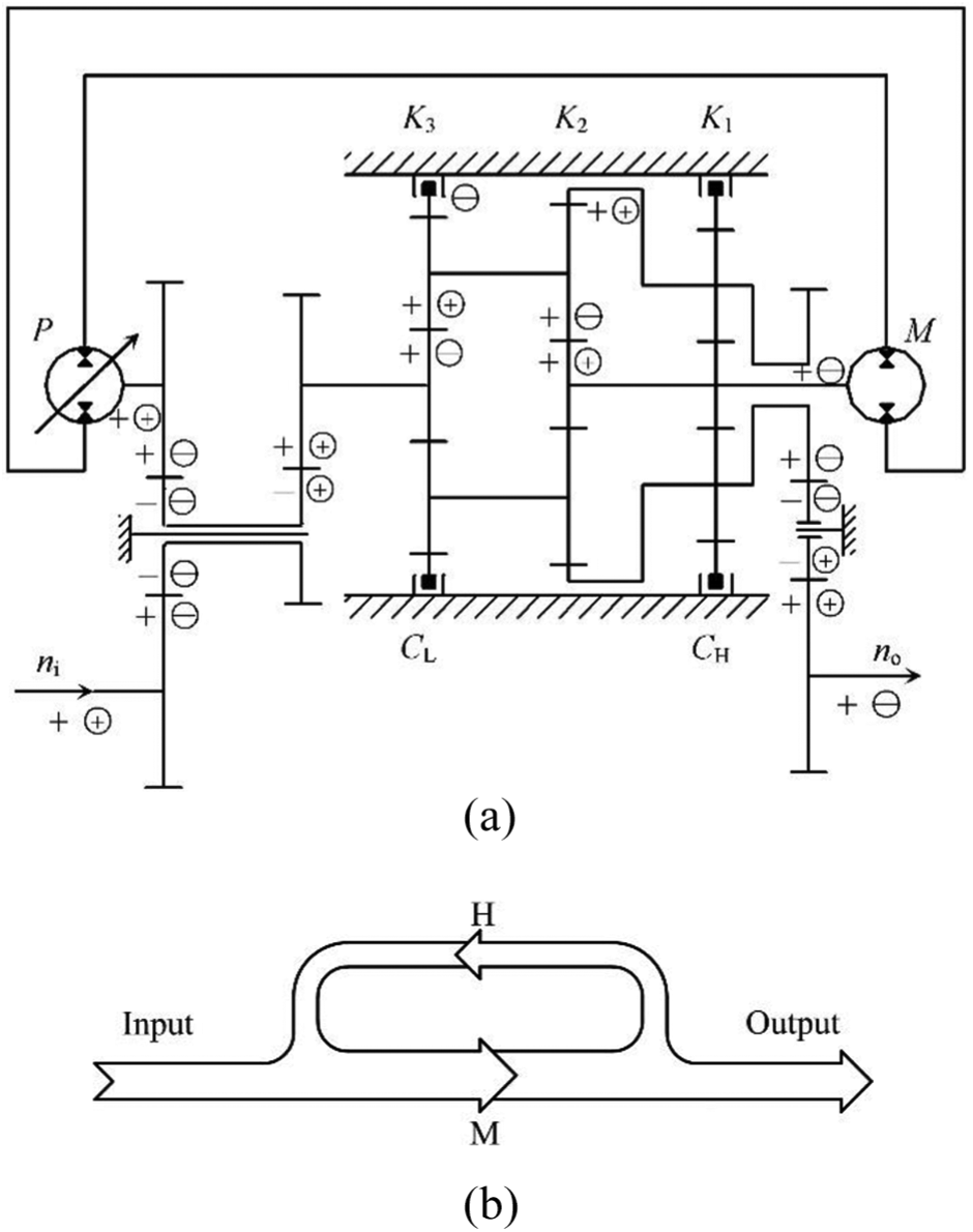
Figure 1 is the structure diagram of an arithmetic two-range HMT. The split unit consists of fixed-shaft gearsets. The hydraulic transmission unit consists of the variable-displacement hydraulic component P, the fixed-displacement hydraulic component M, and hydraulic pipelines. The mechanical transmission unit consists of the planetary gearset K3 and the brake CL. The planetary gearsets K1 and K2, together with the brake CH, form the confluence unit. ni and no represent respectively the input and output speed for the system.

Diagram of an arithmetic two-range HMT.
In hydraulic range (H range), the brake CH is engaged and the planetary gearset K1 works. In hydro-mechanical range (HM range), the brake CL is engaged, and the planetary gearsets K2 and K3 work.
In general power shift process, there is a certain time interval between the target range brake engaging and the current range brake disengaging, or there is a short-time friction overlap between the two brakes, which would cause a short-time power interruption and greatly affect the shift quality.
According to Hu et al., 14 in power shift process, the to-be-engaged brakes and the to-be-disengaged ones would overlap shortly, that is, the brakes CH and CL are both engaged, while the planetary gearsets K1, K2, and K3 all work.
Characteristics of rotational speed in power shift process
In H range, the brake CH is engaged and the brake CL is disengaged. And the rotational speed relationships between the planetary gearsets K1, K2, and K3 are as follows


where k1, k2, and k3 represent respectively the characteristic parameters of planetary gearsets K1, K2, and K3. nc1 and nc2 represent respectively the speed of planetary carriers of K1 and K2, r/min. nm represents the speed of fixed-displacement hydraulic component, r/min. Because the fixed-displacement hydraulic component in Figure 1 is a Rexroth hydraulic motor, the speed of fixed-displacement hydraulic component is simply referred to as the motor speed in the following part. nr3 represents the speed difference of brake CL. i2 represents the transmission ratio from the input shaft to the mechanical transmission unit. The equation can be obtained as follows

Equation (4) shows that in H range, there is a fixed speed relationship between nr3 and nm. At the ideal shift timing, in order to make the speed difference of to-be-engaged brake remain zero, the ratio between motor speed and input speed would be

In HM range, the brake CL is engaged and the brake CH is disengaged. And the speeds of planetary gearsets K1, K2, and K3 are as follows


where nr1 is the speed difference of brake CH, r/min.
The following equation can be obtained

Equation (9) shows that in HM range, there is a fixed speed relationship between nr1 and nm. At the ideal shift timing, in order to make the speed difference of to-be-engaged brake remain zero, the ratio between motor speed and input speed is the same as in equation (5).
In power shift process, during the double brakes overlapping, nr1 and nr3 are both zero, and the ratio between motor speed and input speed is the same as in equation (5). And if the input speed is a constant value, the motor speed is fixed in power shift process.
In power shift process, during the double brakes overlapping, the ratio between motor speed and input speed is a fixed value. Hence, the ratio between the motor speed and input speed can be established as the online identification criterion for power shift timing. Equation (5) shows that in respect of testing the motor speed and the input speed, the shift from H range to HM range has the same ideal power shift condition as that of from HM range to H range.
After power shift, the direction of power flow in hydraulic circuit is reversed, high and low pressure circuits swap, and the functions of hydraulic components are interchanged. In H range, the variable-displacement hydraulic component P works as a pump, and the fixed-displacement hydraulic component M works as a motor. The flow rate relation between these two hydraulic components is as follows

where Vg represents the maximum working displacement of variable-displacement hydraulic component, m3/r. Vm represents the displacement of fixed-displacement hydraulic component, m3/r.
In the HMT shown in Figure 1, the maximum displacement of two hydraulic components is equal: Vg =Vm. The speed relation can therefore be written as

In the prior transmission, the speed of variable-displacement hydraulic component is
where i1 is the transmission ratio from input shaft to hydraulic transmission unit.
Substituting from equation (12) into equation (11), the equation of speed is obtained as
Hence, at the ideal shift timing from H range to HM range, the displacement ratio is

In HM range, the variable-displacement hydraulic component P works as a motor, and the fixed-displacement hydraulic component M works as a pump. The flowrate relation is

Similarly, from HM range to H range, the displacement ratio of variable-displacement hydraulic component at ideal power shift timing is

For the shift from H range to HM range, and the shift from HM range to H range, the ratios between motor speed and input speed at the respective ideal power shift timings are equal. However, as shown in equations (14) and (16), due to the influence of volumetric efficiency, the displacement ratios at the ideal power shift timings of these two shift conditions are different. Consequently, it is more reasonable to identify power shift timing online based on the ratio between motor speed and input speed.
Characteristics of torque and power in power shift process
Define the pressure difference of closed hydraulic circuit as

where p1 and p2 are the high and low pressures in closed hydraulic circuit, respectively.
In H range,
When the double brakes overlap, with a pressure difference of

(a) Torque characteristics and (b) power characteristics when the double brakes overlap, with a pressure difference of
As shown in Figure 2, when the double brakes overlap, with a pressure difference of
When the double brakes overlap, with a pressure difference of
(a) Torque characteristics and (b) power characteristics when the double brakes overlap, with a pressure difference of
As shown in Figure 3, when the double brakes overlap, with a pressure difference of

(a) Torque characteristics and (b) power characteristics when the double brakes overlap, with a pressure difference of
As shown in Figure 4, when the double brakes overlap, with a pressure difference of

(a) Torque characteristics and (b) power characteristics when the double brakes overlap, with a pressure difference of
As shown in Figure 5, when the double brakes overlap, with a pressure difference of

(a) Torque characteristics and (b) power characteristics when the double brakes overlap, with a pressure difference of
As shown in Figure 6, when the double brakes overlap, with a pressure difference of

(a) Torque characteristics and (b) power characteristics when the double brakes overlap, with a pressure difference of
As shown in Figure 7, when the double brakes overlap, with a pressure difference of

(a) Torque characteristics and (b) power characteristics when the double brakes overlap, with a pressure difference of
As shown in Figure 8, when the double brakes overlap, with a pressure difference of
A conclusion can be drawn from the above-mentioned power characteristics: when the double brakes overlap, in condition of various pressure differences, powers transmitted by hydraulic branch and mechanical branch are shown in Table 1.
Powers transmitted by hydraulic branch and mechanical branch in condition of various pressure differences.

In summary, in power shift process, during the double brakes overlapping, if the closed hydraulic circuit has different pressures, the torque and power characteristics of HMT would also be different. In the power shift process, the pressure change in closed hydraulic circuit can transfer the torque and realize power transition.
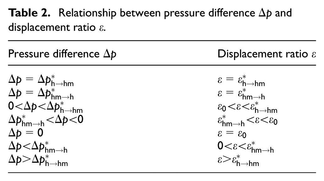
Relation between pressure and displacement in power shift process
In power shift process, when the double brakes overlap, the ratio between motor speed and input speed is a fixed value. And the speed ratio between fixed-displacement hydraulic component and variable-displacement hydraulic component is a fixed value. The pressure in low pressure chamber of closed hydraulic circuit remains unchanged. Taking the high-pressure circuit as an equivalent chamber, the pressure equation of high-pressure chamber is

where p is the pressure in high-pressure chamber of closed hydraulic circuit, V is the volume of high-pressure chamber, and qi and qo are respectively the input and output flowrate in the high-pressure chamber.
When the high-pressure chamber in H range is the high-pressure side, that is, when p1 represents high-pressure side, the variable-displacement hydraulic component works as a pump, whereas the fixed-displacement hydraulic component works as a motor. The equation is as follows

where E1 is the effective oil bulk modulus in high-pressure chamber V1 when it is in H range.
Taking the leakage of hydraulic component as the equivalent of external leakage, the leakage flowrate of variable-displacement hydraulic component would be

where Cs is the leakage coefficient of hydraulic component and
In power shift process, when the pressures in closed hydraulic circuit are stable, there would be

Considering Vg = Vm, the equation would be

According to equation (22), in power shift process, when p1 represents the high-pressure side, there is a functional relationship between the displacement ratio and the pressure difference. Hence, when p1 represents the high-pressure side, the pressures in closed hydraulic circuit can be controlled by regulating the displacement ratio. In power shift process, when the high-pressure chamber in HM range is the high-pressure side, that is, when p2 represents the high-pressure side, the variable-displacement hydraulic component works as a motor, and the fixed-displacement hydraulic component works as a pump. The equation would be
where E2 is the effective oil bulk modulus in high-pressure chamber V2 when it is in HM range.
The leakage flowrate of fixed-displacement hydraulic component would be

In power shift process, when the pressures in closed hydraulic circuit are stable, there would be
Considering Vg = Vm, the equation would be

According to equation (26), in power shift process, when p2 represents high-pressure side, there is a functional relationship between the displacement ratio and the pressure difference. Therefore, when p2 represents the high-pressure side, the pressures in closed hydraulic circuit can be controlled by regulating the displacement ratio.
In power shift process, during the double brakes overlapping, when the hydraulic system remains stable, under different displacement ratios
Relationship between pressure difference
In summary, in power shift process, when the double brakes overlap, by regulating the displacement ratio, we can regulate the pressures in closed hydraulic circuit and control the pressures reversal.
Tests on power shift characteristics
A HMT test bench is built to carry out experiments on the characteristics of power shift. The schematic diagram of test bench for HMT power shift is shown in Figure 9. The photograph of test bench is shown in Figure 10.
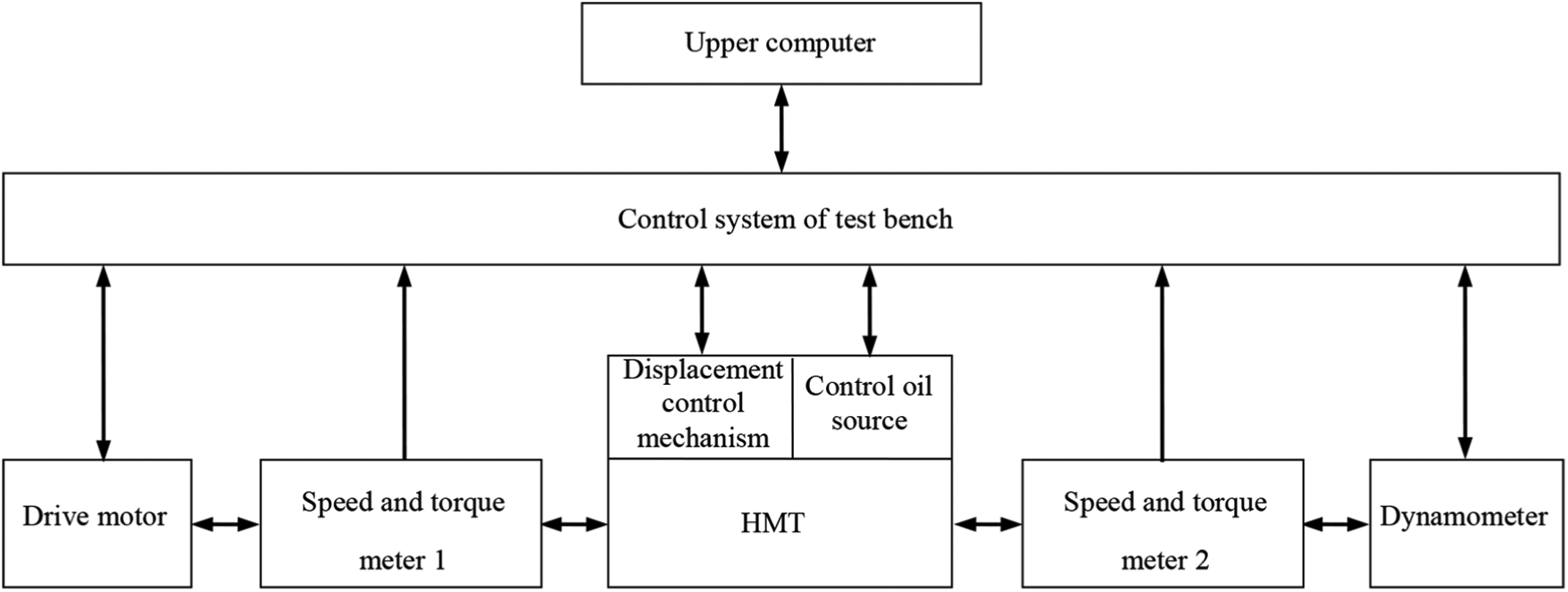
The schematic diagram of test bench for HMT.
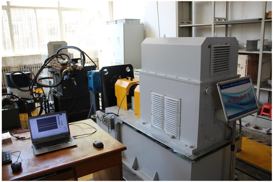
The photograph of test bench.
The test bench is a closed-electric transmission test bench. The drive motor is a variable frequency motor with a rated power of 250 kW. The dynamometer is an electric dynamometer with a rated power of 200 kW. The two speed and torque meters are exactly the same, and their models are all T40. The maximum speed range is 6000 r/min, and the maximum torque range is 1000 N m. The control oil source is provided by a hydraulic power station. The upper computer controls the test bench through the control system of test bench. Two pressure sensors are installed on the variable-displacement hydraulic component of HMT, to measure the pressures in closed hydraulic circuit. The variable-displacement hydraulic component is a Rexroth’s A4VG variable-displacement pump with its own displacement servo control mechanism. By adjusting the current of the displacement proportional solenoid valve (the displacement control current for short), the displacement ratio can be adjusted to realize the speed regulation in range.
The power shift of HMT is a complex dynamic process. In order to study the characteristics of power shift with different pressure differences in hydraulic circuit, the dynamic process of power shift is prolonged during the test. The dynamic process can be regarded as a superposition of several steady-state processes. The input speed remains at 1000 r/min, and the load torque is 150 N m. The power shifts from H range to HM range, and the time for the overlapping of double brakes is prolonged to 20 s. The displacement ratio is regulated. Brake pressures and displacement regulation process are shown in Figure 11(a). Pressures in closed hydraulic circuit are shown in Figure 11(b), and the motor speed and the output speed are shown in Figure 11(c). In Figure 11(b), H, shift, and HM respect respectively H range, power shift, and HM range. (1)–(5) correspond respectively to

Characteristics of pressures in closed hydraulic circuit and rotational speed during the shift from H range to HM range: (a) brake pressures and displacement control current, (b) pressures in hydraulic circuit, and (c) speeds.
As shown in Figure 11, during the power shift from H range to HM range, when the displacement control current is maintained at 548 mA, the pressure change in hydraulic circuit is only 0.6 MPa. It shows that after the target range brake is engaged, the pressure and power characteristics of HMT will remain unchanged if the displacement ratio is unchanged. In the test, the pressure change in hydraulic circuit is caused by the test error of the power shift timing. The displacement control current is reduced step by step from 547 to 482 mA, and the pressures in hydraulic circuit are gradually reversed. When the time for the overlapping of double brakes is prolonged to 20 s, if the displacement ratio is adjusted reasonably, the pressure and power characteristics will appear in five conditions. Before and after the power shift, the motor speed steady with no fluctuation, and the output torque fluctuation is only 5 N m.
The input speed remains at 1000 r/min, and the load torque is 150 N m. The power shifts from HM range to H range, and the time for the overlapping of double brakes is prolonged to 20 s. The displacement ratio is regulated. Brake pressures and displacement regulation process are shown in Figure 12(a). Pressures in closed hydraulic circuit are shown in Figure 12(b), and the motor speed and the output speed are shown in Figure 12(c). In Figure 12(b), H, shift, and HM respect respectively H range, power shift, and HM range. (1)–(5) correspond respectively to

Characteristics of pressures in closed hydraulic circuit and rotational speed during the shift from HM range to H range: (a) brake pressures and displacement control current, (b) pressures in hydraulic circuit, and (c) speeds.
As shown in Figure 12, during the power shift from HM range to H range, when the displacement control current is maintained at 482 mA, the pressure change in hydraulic circuit is only 0.6 MPa. It shows that after the target range brake is engaged, the pressure and power characteristics of HMT will remain unchanged if the displacement ratio is unchanged. In the test, the pressure change in hydraulic circuit is caused by the test error of the power shift timing. The displacement control current is increased step by step from 482 to 547mA, and the pressures in hydraulic circuit are gradually reversed. When the time for the overlapping of double brakes is prolonged to 20 s, if the displacement ratio is adjusted reasonably, the pressure and power characteristics will appear in five conditions. Before and after the power shift, the motor speed remains steady with no fluctuation, and the output torque fluctuation is only 4.2 N m.
As shown in Figures 11 and 12, when the input speed remains fixed, if the shift timing is suitable, the motor speed and output speed can remain steady and unchanged. After the target range brake is engaged, the pressure and power characteristics of HMT will remain unchanged if the displacement ratio is unchanged. At this stage, the pressure and power characteristics of HMT are consistent with the current range. So this stage can be called the prior stable stage. In power shift process, when the double brakes overlap, by regulating the displacement ratio, we can regulate the pressures in closed hydraulic circuit and control the pressure reversal. The pressure and power characteristics appear in five conditions. If the displacement ratio is adjusted reasonably, before the current brake is disengaged, the pressure and power characteristics will be consistent with the target range. So this stage can be called the post stable stage. This power shift method can eliminate the speed fluctuation, control the pressure reverse actively, and realize the full power output.
Full power shift method
Based on the theoretical analysis and experimental studies above-mentioned, a new full power shift method is proposed by taking into consideration two controlling factors: the double brakes overlapping and regulating the displacement ratio. The process of full power shift shall be divided into five stages: current range, prior stable stage, power transition stage, post stable stage, and target range. The current range corresponds to H range in Figure 11(b) and corresponds to HM range in Figure 12(b). The prior stable stage corresponds to phase 1 in Figures 11(b) and 12(b). The power transition stage corresponds to phases 2–4 in Figures 11(b) and 12(b). The post stable stage corresponds to phase 5 in Figures 11(b) and 12(b). The target range corresponds to HM range in Figure 11(b) and corresponds to H range in Figure 12(b). The ratio between motor speed and input speed shall function as the criterion of ideal power shift timing. For the HMT working at current range, when the ideal power shift timing comes, the target range brake would be engaged with zero speed difference. And when the HMT comes to the prior stable stage, its torque and power characteristics remain unchanged. Regulating properly the displacement ratio so as to make the high- and low-pressure sides of hydraulic circuit interchange. The original low-pressure side pressurizes to the target range pressure, and the torque moves from current range brake to target range brake. HMT comes to the post stable stage with its torque and power characteristics remaining identical with those of the target range. The current range brake is disengaged at zero torque, and HMT enters the target range. The power shift process is completed. The interchange between high and low pressure and power transition is completed when the double brakes overlap. In the power shift process, the output power can be transmitted normally in full power.
Full range speed changing tests on full power shift
Full range speed changing tests on full power shift of HMT are carried out. The input speed remains at 1000 r/min, and the load torque is 100 N m. In the power shift process, the time for the overlapping of double brakes is shortened to 2 s. From 232.5 to 234.5 s, the power shifts from H range to HM range. From 343 to 345 s, the power shifts from HM range to H range. In Figure 13(a)–(f) shows the input voltage of amplifiers, the control current, the brake pressures, the pressures in closed hydraulic circuit, the motor speed, and the output speed, respectively.

Characteristics of full range speed changing for full power shift of HMT: (a) input voltage of amplifiers, (b) control current, (c) brake pressures, (d) pressures in hydraulic circuit, (e) speed of fixed-displacement hydraulic component, and (f) output speed.
As shown in Figure 13, in the power shift from H range to HM range, the pressure reversal of the closed hydraulic circuit is completed before 234.5 s. In the power shift from HM range to H range, the pressure reversal is completed before 345 s. In the full power shift, even if the time for the overlapping of double brakes is shortened to 2 s, the active control of the pressure reversal can be realized. In the tests, this full power shift method can attain continuous variable changes for full range speed ratio, and the motor speed in power shift can be smooth with little fluctuation.
Conclusion
Through theoretical analysis of the speed characteristics, this article proves that the ratio between the motor speed and input speed of the system is a fixed value in power shift process. Therefore, it is rather reasonable to choose this parameter as the criterion for the ideal power shift timing of HMT.
Combining theoretical analysis with experimental studies, this article explores the torque and power characteristics in power shift process. The results show that in the power shift process, the pressures in closed hydraulic circuit can be regulated by adjusting the displacement ratio, and the pressure can be reversed to achieve power transition. Moreover, such regulation can make the pressure and power characteristics of HMT remain identical before and after the current range brake is disengaged.
This article puts forward a new full power shift method of HMT and divides the process into five stages: current range, prior stable stage, power transition stage, post stable stage, and target range. Interchange between high and low pressure and power transition is completed when the double brakes overlap. In this power shift process, output power can be transmitted normally in full power.
Footnotes
Handling Editor: Jose Ramon Serrano
Declaration of conflicting interests
The author(s) declared no potential conflicts of interest with respect to the research, authorship, and/or publication of this article.
Funding
The author(s) disclosed receipt of the following financial support for the research, authorship, and/or publication of this article: This work is supported by the National Natural Science Foundation of China (grant nos 51675462, 51175449).