
Abstract
A sub-shift control algorithm was proposed for an agricultural tractor with hydro-mechanical transmission. The hydro-mechanical transmission investigated in this study consists of a hydro-static unit and planetary gear sets which provide a continuously variable transmission function and four sub-shift gears. The sub-shift needs to be carried out at the hydro-static unit stroke where the speed of the off-going and on-coming clutches is synchronized. To reduce the hydro-static unit stroke error due to the nonlinear characteristic, the hysteresis characteristic was investigated in the test bench and a hysteresis compensator was developed. Using the compensator in the feedforward loop, a hydro-static unit stroke control algorithm was proposed and validated via experiment. To prevent the torque interruption during the sub-shift, a time delay of the off-going clutch was proposed. In addition, a hydro-static unit stroke duration which maintains the target stroke during the sub-shift was suggested to reduce the speed difference between the clutch plates. The sub-shift control algorithm including the hysteresis compensation, time delay of the off-going clutch, and hydro-static unit stroke duration was evaluated via experiment. It was found from the experimental results that the sub-shift was performed smoothly without the torque interruption, even in the acceleration state when large inertial torque change occurred.
Introduction
In tractors, manual transmission has been widely used. Manual transmission has many advantages such as a simple structure, low price, and high efficiency. However, in regard to the shift of the manual transmission, the driver must stop the tractor and manipulate the gear shift manually using the clutch pedal and gear lever. To overcome this inconvenience, power-shift transmission and continuously variable transmission (CVT) have been investigated. The power-shift transmission uses multiple clutch packs and an electronic control system for the automatic shift, but it is not a fully automatic transmission because the clutch pedal needs to be operated by the driver for the shifting range selection. CVT has been considered as an alternative for the future tractor transmission. Among the various types of CVTs, hydro-static transmission (HST) has the advantages of high power transmission and high durability, 1 but its low efficiency and noise problem have been mentioned as major drawbacks. 2 To overcome these problems, a hydro-mechanical transmission (HMT) has been investigated. The HMT consists of a hydro-static unit (HSU) and planetary gear sets with clutches and brakes, which provides sub-shifts as well as a continuously variable function. Since the HMT has a wider gear ratio and higher efficiency than HST, it began to be used in agricultural tractors such as the “Vario” from the Fendt.1,3–5
The HMT investigated in this study has four clutches to provide four sub-shift gears, and one clutch is used at a time to transmit power. Because the sub-shift is performed when the speed of the engaging and disengaging clutches is the same, a smooth gear shift can be obtained without torque shock. However, in a real system, it is difficult to obtain a smooth gear shift because of the speed difference between the engaging and disengaging clutches, which is due to the nonlinear characteristics of the HSU and hydraulic valves that are used to control the clutch speed. In HSU, hysteresis for the swash plate which causes negative and positive error of the swash plate angle is a typical example of the nonlinear characteristics.
To analyze the dynamic characteristics of an HSU swash plate, factors which influence the speed ratio of the HSU were deduced from a state variable analysis.6,7 The effect of the bulk modulus on performance of an HSU was investigated,8,9 and fuzzy proportional–integral–derivative (PID) control was proposed to compensate for the effect of the bulk modulus in HSU. 9 H∞ control was proposed, considering the flow control valve characteristics for robust control of the multi-input multi-output (MIMO) system in the HSU of the earth moving vehicle. 10 To minimize the energy loss of the swash plate actuating system in the HSU, a robust control was proposed using the direct drive valve. 11 In addition, to prevent jerk in the HSU, the neutral valve of the HSU was tuned according to jerk phenomenon analysis. 12 For the HMT system, proportional–integral (PI)/PID control based on the first-order approximation model was proposed and its performance was evaluated.13,14 However, nonlinear terms such as hysteresis for the swash plate control valve were not considered.
To achieve a smooth shift quality, many studies have been performed regarding automobile technology for passenger cars. The gear shift process for a wet clutch was analyzed for the dual clutch transmission of the passenger car in order to conduct smooth shifts during the clutch engagement and disengagement. 15 A control method for the clutch shifting process using linear quadratic optimal control theory was proposed. 16 For an agricultural tractor, the electric current compensation of the hydraulic valves was designed for the clutch control. The compensator determines overlap time for the clutch engagement and disengagement using the experimental results of clutch pressure response in time domain. 13 To evaluate the performance of the shift quality of an agricultural tractor, an automatic pressure tuning controller was proposed which uses the speed difference during the gear shift for a power-shift transmission. 17
In this study, a sub-shift control algorithm is proposed to improve the shift quality of an HMT for a target tractor. To achieve an accurate speed synchronization of the off-going and on-coming clutches, a compensator is proposed to reduce the hysteresis effect of the HSU stroke control system using the inverse hysteresis model. In addition, a time delay of the off-going clutch and HSU stroke duration were suggested in order to prevent torque interruption during the sub-shift. The sub-shift control algorithm was evaluated through a test bench.
Modeling of HMT
Figure 1 shows a schematic diagram of the HMT system of the target tractor. The HMT consists of an HSU, a compound planetary gear set, and a sub-shift part. The HSU has a CVT feature to change the speed ratio between the engine and wheel speed. The compound planetary gear set consists of two planetary gears. Each planetary gear is connected by the pinion gear and the carrier. The carrier (denoted as “C1”) and “C2” are connected to CL1 (clutch 1) and CL3 (clutch 3) of the sub-shift part. The second sun gear (denoted as “S2”) is connected to CL2 (clutch 2) and CL4 (clutch 4). The sub-shift is performed when the speed of the engaging clutch is equal to that of the disengaging clutch. The output of the sub-shift part is connected to the FOR (forward clutch) and REV (reverse clutch). The direction movement for the tractor can be changed by the FOR and REV.

Schematic diagram of the target tractor.
The dynamic equation of the target HMT in Figure 1 can be derived as follows


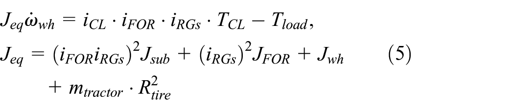
where J is the inertia, ω is the rotational speed, T is the torque, i is the gear ratio, η is the efficiency, P is the pressure, D is the displacement of the HSU, β is the bulk modulus of the oil, V is the volume, m is the mass, and R is the radius. The subscripts e, S1, e_p, p, m, m_R, FOR, RGs, R, wh, and load represent the engine, the first sun gear, from the engine to the pump, the HSU pump, the HSU motor, from the motor to the ring gear, the forward gear, the reduction gears, the ring gear, the wheel, and the load at the wheel, respectively. The subscripts CL, tractor, and tire refer to the clutch, the target tractor, and the tire of the wheel, respectively. The torque equation for the compound planetary gear is derived using lever analysis in Figure 2.

Torque lever analysis of the compound planetary gear set.
From the torque lever in Figure 2, TC and TS2 are derived as follows
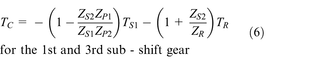

where Z is the number of gear teeth, and the subscripts S2, P1, and P2 represent the second sun gear, the first pinion gear, and the second pinion gear, respectively.
As shown in equations (1)–(7), the total gear ratio of the target tractor is changed by istroke and the sub-shift gear. To compute the speed ratio between the wheel speed and the engine speed, speed ratio equations are derived as follows

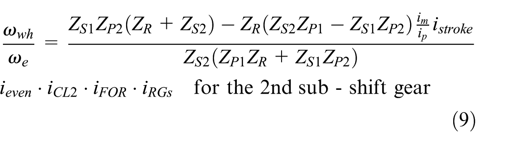


where the subscripts even and odd represent the even clutch shaft and the odd clutch shaft, respectively. Using above equations, the relationships between the speed ratio and istroke for each sub-shift gear are illustrated in Figure 3.

Sub-shift for the speed ratio.
In Figure 3, the speed ratio range of each sub-shift gear is plotted with respect to the speed ratio. The speed ratio (SR) is defined as the ratio of the wheel speed ωwh to the engine speed ωe. Each line shows the speed ratio range at each gear. When the engine is on, the istroke sets out from istroke = 0.87 with the first gear, where the wheel speed ωwh = 0. This allows engine ignition without an engine clutch or torque converter. If the engine speed is maintained, the wheel speed increases as istroke decreases. The sub-shift is performed at the point of intersection between each line. For example, the 1st ↔ 2nd sub-shift is carried out at SR = 0.0171. At this point, the speed difference between the clutch disk of the first and second gear is theoretically zero, and it is possible to smoothly shift without torque shock. However, if accurate istroke is not realized when sub-shift, the speed difference between the clutch disks and plates causes torque shock, which in turn deteriorates the shift quality.
HSU stroke control with hysteresis compensation
HSU swash plate control system
Figure 4 shows the swash plate control system. The solenoid valve has four ports and three positions. Oil flow comes from the valve body through the “P” port, and its direction is controlled by the transmission control unit (TCU). The position of the piston in the cylinder is determined by the spring force and pressure difference. A lever which is connected to the piston moves the swash plate angle, which changes from −45° to 45°. From this, the speed ratio between the pump and motor varies from −1 to 1. The dynamic equations of the swash plate control system are given as follows

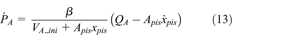

where m is the mass, b is the damping coefficient, k is the spring coefficient, x is the displacement, Q is the flow rate, and A is the area. The subscripts pis, A, B, and ini represent the piston, the left and right side of the cylinder, and the initial state, respectively. As shown in equations (12)–(14), the swash plate system was modeled as a linear system; however, in a real system, an effect due to hysteresis exists, which is typical for nonlinear elements. 7
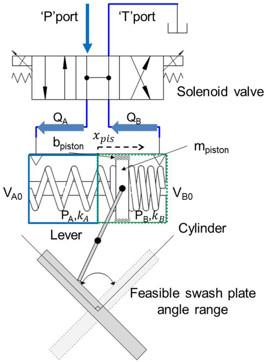
Swash plate control system.
To control the system accurately, nonlinear effects, such as hysteresis of the swash plate control system, should be compensated for. Many studies on the swash plate control of HSU have been carried out, such as PI feed-back control, H∞ control, and fuzzy control.9–11,13,14 However, there are few studies on the hysteresis characteristic of the swash plate control system.
Hysteresis model and identification
To investigate the hysteresis characteristic of the target HSU, experiments were performed. Figure 5 shows a schematic diagram of the test bench of the target HMT. The test bench consists of a traction motor, HMT, valve body, cooler, and dynamo motor. Torque and speed sensors were mounted on the input and output shafts of the HMT. For data acquisition, a MicroAutoBoxII by dSPACE was used to transmit the signals and collect the data. From the test bench, the hysteresis characteristic of the swash plate control system was investigated.

Test bench of the HMT.
Figure 6 shows the experimental results of the hysteresis for the swash plate control system. The solid line is measured from the experiment, while the dotted line is the input command. In the experiment, a ramp-wise istroke command was applied from istroke = 0 to istroke = 1. The subscript cmd denotes the command. The magnitude of istroke changed in a decreasing manner with the same period. The period of the ramp-wise istroke command was selected as T = 40 s, which is slow enough to neglect the transient effect. In this experiment, the static hysteresis characteristic was investigated. The experiment was carried out only for a positive istroke because the target HSU shows exactly the same response as for a negative istroke.

Hysteresis for the swash plate control system: (a) ramp input and (b) increasing and decreasing input.
It is shown in Figure 6(b) that istroke has a dead band until istroke = 0.04 when it starts from istroke = 0. When the istroke command begins to decrease from istroke = 1, istroke shows a similar dead band characteristic, which causes hysteresis. The hysteresis region of istroke moves to the left side as istroke increases, showing lower values than the istroke command.
As shown in Figure 6(b), the hysteresis characteristic of the control system is not symmetric with respect to the istroke command. The value of the difference between the increasing and decreasing istroke is 0.05. This hysteresis affects the shift performance of the HMT. For example, when the pump rotates at 2500 r/min at istroke = 0.5, the difference of the motor speed turns out to be about 150 r/min due to the hysteresis. To compensate for the error due to hysteresis, an exact model which represents the hysteresis is required.
Several hysteresis models were investigated regarding rate-independent hysteresis, such as the Preisach model 18 and the Prandtl–Ishlinskii model. 19 Various systems can be modeled accurately using the Preisach model, but it is too complicated to use for real-time control. 20 The classical Prandtl–Ishlinskii model is easy for designing an inverse model, but it can only be used in a system which has symmetric hysteresis.20,21 Since the swash plate control system shows an asymmetric hysteresis characteristic (Figure 6), a modified Prandtl–Ishlinskii (MPI) model is suggested to model the hysteresis characteristic of the target system.20,22
The MPI model is one of the subclasses of the Preisach model, which consists of an elementary backlash operator and a dead-zone operator. The backlash operator and dead-zone operator are described as


where Hr is the backlash operator, Sd is the dead-zone operator, u is the input command, ist_ini is the initial value, r is the threshold value of the backlash, Ts is the sampling time, and d is the threshold value of the dead-zone. The backlash operator and dead-zone operator represent nonlinearities of the hysteresis. The backlash operator and dead-zone operator are used with weight values. The generalized backlash operator and the generalized dead-zone operator are given as


where ws is the weight value of the dead-zone operator and wh is the weight value of the backlash operator. To improve the accuracy of the MPI model, multiple threshold values and weight values are used, and each operator is expressed in a vector form.20,22 Based on equations (17) and (18), the general equation of the MPI model is represented as

where
To find out the weight values, a nonlinear least square optimization method was conducted using MATLAB. The weight vectors are needed to reduce the error between the hysteresis results of the experiment and the MPI model. The subject function is set using the error model and is given as
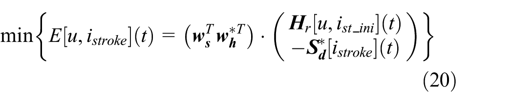
where * represents the inverse. During the iteration process, ws and wh are identified and are used in the MPI model, that is, equation (17). To verify the identified MPI model, it is compared with the test results in Figure 6.
Figure 7 shows the comparison between the MPI model and the experimental result. The dotted line shows istroke in Figure 6, and the solid line shows the result of the MPI model. To measure the level of correlation between the measured istroke and the MPI model, the normalized cross-correlation power (NCCP) is used. 23 The NCCP between the test data and the MPI model is calculated as 0.99 for 0–150 s, which demonstrates the accuracy of the MPI model.

Comparison between the MPI model and experimental results.
Inverse MPI model
Using the MPI model, a proper input command which provides the desired output can be obtained from the inverse of the MPI model. The inverse MPI model is derived from equation (17) as20,22

Each parameter in equation (21) can be calculated from the identified MPI model. The inverse MPI model, that is, equation (21), is used as a compensator to calculate the proper input command.
Figure 8 shows the performance of the compensator. Experiments were performed using the hysteresis compensator for a ramp-wise input with a period of T = 40 s (0.025 Hz). It is seen from Figure 8 that istroke follows the istroke command, showing almost no hysteresis. From the test results (Figure 8), it can be seen that the steady-state error due to the hysteresis can be eliminated almost entirely using the compensator.

Performance of the compensator.
HSU stroke control
Using the inverse MPI model (hysteresis compensator), an istroke control system was designed.
Figure 9 shows a block diagram of the istroke control. The PI control was used with a feedforward inverse hysteresis model. Each output from the inverse MPI model and the PI controller are combined and gives the proper current value to the swash plate control system. The PI gains were designed using the transfer function of the swash plate control system and were tuned in the test bench.

Block diagram of the istroke control.
To evaluate the performance of the istroke control algorithm, experiments were performed. In the experiments, the control performances with the hysteresis feedforward compensator and without the compensator were compared for an up and down step-wise input of the istroke command, with istroke ranging from 0 to 0.5. It is seen from Figure 10 that the response time is almost the same for both controls. However, the control without the compensator shows an overshoot and undershoot for the step-wise up and down input command. For the downward step-wise input, istroke remained constant at 0.016 for about 1 s when istroke_cmd = 0. The reason for this phenomenon is that the hysteresis characteristic was at a steady state. As shown in Figure 6, the swash plate control system has the dead band at istroke = 0, and it was hard to control istroke accurately in the dead band only by PI control. However, istroke with the compensator followed the istroke command, even if it shows some error around istroke_cmd = 0 for the downward step input. This improved performance owes itself to the hysteresis compensator.

Comparison result (step response).
Figure 11 shows the experimental results of the istroke control with and without the compensator for the ramp-wise input. The ramp-wise istroke command was applied from istroke_cmd ranging from −1 to 1 with a period of T = 10 s (0.1 Hz). This frequency is the most commonly used region in real applications of the HSU stroke control in the target tractor. From Figure 11, it is observed that the istroke error by the compensator control is much smaller than that without the compensator. It is also noted that the istroke error increased when the istroke command changed the direction at istroke_cmd equal to −1 and 1. This is due to the dead band characteristic, as shown in Figure 6(b).

Comparison result (ramp-wise response).
It is found from the experimental results (Figures 10 and 11) that the hysteresis compensator proposed in this study provides an improved tracking performance of the swash plate control system of the target HSU.
Sub-shift clutch control and HSU stroke duration
The tractor with HMT investigated in this study has a sub-shift gear which consists of four clutches, CL1–CL4 (Figure 1). Using the sub-shift, the target tractor can expand its speed range. In general, during the gear shift, a clutch slip occurs between the off-going and on-coming clutches, and inappropriate slip may cause a torque shock and wear of the clutch. In conventional automatic transmission of the passenger cars, electronically controlled proportional valves are used to control the clutch slip.
Considering the cost and control problems for the target tractor, we tried to develop an HMT using an on/off valve instead of the electronically controlled proportional valves. Theoretically, the sub-shift in the target HMT can be performed at the intersection point where the speed of the off-going and on-coming clutches is the same (Figure 3). However, there may exist a speed difference between the clutches due to the response characteristic of the sub-shift clutch system.
Figure 12 shows the schematic diagram (a) and AMESim model (b) of the sub-shift clutch system. The hydraulic oil flow is supplied from the oil pump and the relief valve maintains the line pressure. When the clutch engaging signal is applied, the on/off valve is opened and the oil flows to the clutch piston. When the pressure force becomes larger than the return spring force, the clutch piston begins to move and then contacts the rubber ring, which is installed between the plate and disk. The rubber ring plays a role in maintaining the clearance between the plate and disk when disengaging. In Figure 12, each rubber ring is modeled as a spring and damper. A check ball in the clutch piston is used to prevent the effect of the centrifugal force of the oil when disengaging. Using an AMESim model (Figure 12(b)), simulations were performed for the clutch engaging and disengaging states.

Schematic diagram and AMESim model of the sub-shift clutch system: (a) sub-shift clutch and (b) AMESim model.
Figure 13 shows the simulation results for the on-coming (engaging) and the off-going (disengaging) clutches. For the on-coming clutch, when the clutch engaging signal is applied at P(t = 0.1 s), the on/off valve starts to open and the clutch pressure begins to increase to Q. In the region P-Q, the pressure response depends on the clutch volume and reaction force of the return spring and the rubber ring. In this study, a nonlinear stiffness model of the rubber ring was used. The clutch clearance decreases in the region P-Q and reaches 0 mm at the kissing point (Q). From the kissing point, the clutch pressure increases again to the line pressure of 20 bar.

Simulation results for (a) the on-coming and (b) the off-going clutches.
For the off-going clutch, the clutch pressure (a′) decreases exponentially when the disengaging signal is applied.
From the simulation results in Figure 13, it is found that the pressure response of the on-coming clutch has a different characteristic compared with that of the off-going clutch, due to the return spring and the rubber ring stiffness.
It is considered that this different pressure response may cause an interruption of the torque change between the off-going and on-coming clutches. To figure out the effect of the different pressure response, experiments were performed for 1–2 upshift using the test bench.
Figure 14 shows the experimental results of the sub-shift from first to second using the on/off valves. The 1→2 sub-shift signal was applied at t = 0 s when istroke = −0.72. During the sub-shift, the HSU stroke was maintained at istroke = −0.72, where the speed of the on-coming (CL2) and off-going (CL1) clutches is the same (Figure 3). It is observed from Figure 14(a) that the pressure of the off-going (CL1) and on-coming (CL2) clutches shows a similar response with those of the simulation results. However, as shown in Figure 14(b), the torque interruption and torque shock occur during the shift. The reason of the torque interruption and torque shock can be analyzed by region as follows.

Experimental results for the sub-shift from 1st to 2nd: (a) pressure, (b) HMT output torque, (c) HMT output speed, and (d) CL2 slip speed.
The HMT output torque (b) decreases with the CL1 pressure. The HMT output torque remains zero in R-S showing the torque interruption. The HMT output speed decreases as the output torque decreases. When the clutch CL2 reaches the kissing point (S), the HMT output torque begins to increase. The HMT output torque increases rapidly, showing the torque shock in the region S-V, because the clutch plate engages with the output shaft that is connected to the large vehicle inertia during slipping. Unlike the simulation results in Figure 14, CL2 pressure does not increase after the kissing point; this is because the line pressure is not recovered in the region S-V. At V, the CL2 pressure increases with the line pressure. The line pressure decreases as the oil flows to the CL2 clutch (Q-S). The reason why the line pressure is not recovered in S-V is that it takes time to fill up the volume of the other hydraulic circuit considering the lubrication and cooling (“hydraulic circuit A” in Figure 12), which was not considered in the simulation.
It is noted from the experimental results that the pressure response of the on/off valve has a different time delay, 0.02 s for the off-going clutch and 0.07 s for the on-coming clutch, respectively. The reason why the time delay of the on-coming clutch is larger than that of the off-going clutch is due to the oil filling time in the piston.
The HMT output torque (b) and speed (c) show the oscillation after the clutch CL2 is fully engaged at W. This oscillation results from the inertia torque change of the relatively large HMT drivetrain right after the torque shock.
The torque shock in Figure 14 deteriorates the shift quality, that is, the driving comfort. In conventional automatic transmission of the passenger cars, the torque shock can be reduced by the clutch slip control using the electronically controlled proportional valve.15,16,24,25 However, this requires additional cost and accurate control of the clutch pressure. In the tractor, shift quality is not as important in passenger cars and therefore if we can reduce the torque variation using the on/off valves, manufacturing cost can be considerably reduced.
As shown in the experimental results (Figure 14), the torque shock occurs right after the torque interruption. This is because the off-going clutch CL1 is disengaged earlier than the on-coming clutch CL2 engagement. Therefore, if CL1 can be disengaged in proper timing, torque interruption can be prevented.
Sub-shift control algorithm
In this study, a control algorithm which delays the off-going clutch disengagement timing is proposed to prevent torque interruption.
The basic concept of the algorithm is to maintain the sum of the CL1 and CL2 clutch torque during the sub-shift. The clutch torque TCL is represented as

where N is the number of clutch disks and µ is the friction coefficient. The subscript eff represents the effective radius of the clutch disk.
During the sub-shift, the HMT output torque is represented as a sum of the off-going and on-coming clutch torque

where the subscript out represents the HMT output.
The clutch torque changes with the clutch pressure. Assuming that the clutch pressure changes in exponentially, the off-going clutch torque TCL_off can be expressed as follows
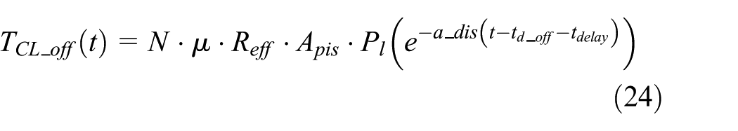
where a_dis is the time constant, Pl is the maximum line pressure when the clutch is fully locked up, td_off is the delay time of the off-going clutch pressure, and tdelay is the delay time which needs to be determined.
Furthermore, when the clutch is engaging, TCL_on is expressed using the following exponential function

where a_eng is the time constant, and td_on is the delay time of the on-coming clutch pressure. It is noted from Figure 14 that the clutch torque is zero, regardless of the CL2 pressure, until the kissing point (S). In the region S-V, the CL2 pressure maintains an almost constant value of PSV. Therefore, equation (25) can only be applied in the region V-W. In this study, TCL_on is calculated using the constant pressure value for S-V and equation (25) for V-W.
Using Tout in Equation (23), the time delay of the off-going clutch tdelay can be obtained for the given load torque, Tout.
The sub-shift control algorithm using the time delay of the off-going clutch was evaluated in Figure 15. Experiments were performed with a 1–2 upshift for the load torques Tout = 100 N m and 300 N m. During the sub-shift, HSU stroke was maintained at istroke = −0.72, where the speed of the off-going and on-coming clutches is equal. The time delay of the off-going clutch tdelay was calculated from equation (23), with tdelay = 0.11 and 0.19 s for the load torques of 100 and 300 N m, respectively.

Experimental results for the sub-shift control algorithm: (a) load torque = 100 N m and (b) load torque = 300 N m.
As shown in the experimental results, the HMT output torque is maintained at the target load torques of 100 and 300 N m without showing the torque interruption and shock. Even though some torque oscillation is exhibited, the magnitude of torque oscillation is much smaller compared with that of without control. Correspondingly, the HMT output speed also maintained a constant speed for both load torques.
It is observed from the experimental results that the CL1 pressure does not show the expected behavior. CL1 pressure is supposed to begin decreasing at Q after the time delay tdelay + td_off from the disengaging command signal, but instead begins to decrease at P following the line pressure. This is because the line pressure decreases due to oil flow shortage when the oil flows to the on-coming clutch, CL2. CL1 pressure begins to decrease at Q, exponentially departing from the line pressure. In spite of the earlier pressure drop in P-Q, the HMT output torque (c) is maintained around the target load torque because the Tout value obtained from equation (23) is large enough to transmit the given load torque.
Similar responses of the CL1 and CL2 pressures are observed for the load torque 300 N m (a′). It is seen that the HMT output torque (b′) is maintained around 300 N m without torque interruption or shock.
HSU stroke control during sub-shift
It is noted that the sub-shift experiments were carried out when the HSU stroke was maintained at a constant value of istroke = −0.72 for the 1–2 upshift. In real operation, however, the HSU stroke is supposed to change its direction right after the sub-shift, as shown in Figure 3. If the HSU stroke control is performed in this way without consideration of the sub-shifting time, it may cause a large torque variation. Therefore, in this study, a HSU stroke duration control is proposed, which maintains the HSU stroke as constant during the sub-shift. The HSU stroke duration time tstroke_d is determined as follows

In equation (26), tdelay and td_off are the time delay of the off-going clutch and on/off valve pressure obtained in the previous section and tzero is the pressure-zero time of the off-going clutch. The pressure-zero time is defined as the time period for which the off-going clutch pressure is zero. The pressure-zero time is required to achieve the fully disengaged state of the off-going clutch when the HSU stroke begins to change the direction right after the sub-shift. Otherwise, the clutch torque occurs due to the clutch slip which may cause a torque fluctuation. The pressure-zero time is obtained from via experiment (Figure 14).
Experiment for the sub-shift control
To evaluate the performance of the sub-shift control algorithm using tdelay of the off-going clutch, experiments were performed. In Figure 16, experimental results are shown when the tractor starts from a standstill state (vtractor = 0 kph) to vtractor = 15 kph during 15 s. In the experiments, the HMT input speed (traction motor) was maintained at 1600 r/min and a constant load torque of 120 N m was applied using a dynamo motor. In addition, the istroke control with the hysteresis compensator developed in this study was applied.

Experimental results for increasing tractor speed: (a) t = 0–20 s and (b) t = 6–11 s.
It is seen from Figure 16(a) that the tractor speed increased to vtractor = 15 kph, showing hesitation whenever the sub-shift occurred. The HMT output torque fluctuated between 170 and 180 N m until the tractor speed reached a value of vtractor = 15 kph and the HSU stroke followed the command stroke. When the tractor speed reached vtractor = 15 kph, the HMT output torque decreased to the given load torque, around 120 N m, and maintained the demanded load torque. During the acceleration period of 15 s, the HMT output torque showed higher values than the demanded torque that is required to meet the acceleration of the large tractor inertia. In Figure 16(b), the time response for t = 6–11 s is shown. It is noted from Figure 16(c′) that the HSU stroke was maintained at a constant value during the sub-shift istroke = −0.72 for the 1–2 upshift and istroke = 0.03 for the 2–3 upshift. The HSU stroke (c′) duration time tstroke_d was obtained from equation (26) as 0.42 and 0.46 s for the 1-2 and 2-3 upshifts, respectively. tdelay was calculated using equation (23) for the target load torque. The HSU stroke followed the command stroke closely without hysteresis by the hysteresis compensator proposed in this study.
From the experimental results in Figure 16, it is found that the hysteresis compensator and sub-shift control algorithm including the HSU stroke duration can provide the satisfactory shift performance using the on/off valve without torque interruption and shock.
Conclusion
A sub-shift control algorithm was proposed for an agricultural tractor with HMT. The HMT investigated in this study consists of a HSU and planetary gear sets which provide a CVT function and four sub-shift gears to expand the gear speed range. Since the sub-shift can be carried out at the HSU stroke, where the speed of the off-going and on-coming clutches is the same, accurate control of the HSU stroke is required. To reduce the stroke error which comes from the nonlinear characteristic of the HSU swash plate control system, the hysteresis characteristic was investigated in the test bench. Based on the inverse MPI model of the identified hysteresis characteristic, a HSU stroke control algorithm was proposed using the feedforward hysteresis compensator. The performance of the HSU stroke control algorithm was validated via experiment, which showed that the stroke error was reduced significantly at the sub-shift point where the stroke changed its direction toward the opposite direction. To prevent the torque interruption when using the on/off valves for the sub-shift, a time delay for the off-going clutch was proposed. The time delay was determined using the clutch torque equations that were constructed based on the pressure response of the off-going and on-coming clutches. In addition, an HSU stroke duration which maintains the target stroke during the sub-shift was suggested to reduce the speed difference between the clutch plates right after the sub-shift. The sub-shift control algorithm including the hysteresis compensation, time delay of the off-going clutch, and HSU stroke duration was evaluated via experiment. It was found from the experimental results that the sub-shift was performed smoothly without torque interruption and shock, even in the acceleration state when large inertial torque change occurred.
Footnotes
Academic Editor: Ling Zheng
Declaration of conflicting interests
The author(s) declared no potential conflicts of interest with respect to the research, authorship, and/or publication of this article.
Funding
The author(s) disclosed receipt of the following financial support for the research, authorship, and/or publication of this article: This research was supported by the Advanced Production Technology Development Program of the Ministry of Agricultural, Food, and Rural Affairs.