
Abstract
In order to improve the shift quality of hydro-mechanical continuously variable transmission, the effect of tangent bulk modulus and different control methods on the shift quality were analyzed. Theoretical analysis and experimental study on the tangent bulk modulus of oil were carried out to obtain the effect law of air content on the tangent bulk modulus of oil. A four-cavity model of a closed hydraulic circuit was established based on a two-stage arithmetic type hydro-mechanical transmission. By means of simulation analysis and experimental study, the effect of the tangent bulk modulus of oil on the shift quality is studied. The lean control method of reasonably controlling displacement ratio and prolonging the reverse time of load torque is put forward. The results show that this method can reduce the fluctuations of the speed of the fixed displacement motor and the oil pressure of the original low-pressure side. This method can also improve the shift quality and provide reference for the study of the shift process of hydro-mechanical continuously variable transmission.
Keywords
Highlights
Theoretical analysis and experimental study on the tangent bulk modulus of oil were carried out to obtain the effect law of air content on the tangent bulk modulus of oil.
By means of simulation analysis and experimental study, the effect of the tangent bulk modulus of oil on the shift quality is studied.
The control method of reasonably controlling displacement ratio and prolonging the reverse time of load torque is put forward.
Introduction
Hydro-mechanical continuously variable transmission (HMT) is a dual-power flow transmission composed of hydraulic power transmitting unit and mechanical power transmitting unit in parallel. 1 With the combination of hydraulic and mechanical units, continuous stepless changes in transmission ratio can be realized to make the engine work in the efficient zone. In addition, the oil can buffer and reduce the transient load on the transmission system to effectively improve the service life of vehicles, which is especially important for engineering vehicles working in harsh environments for a long time. HMT, a high-power, high-efficiency, and adaptable stepless transmission, is one of the ideal transmission forms for vehicles that not only meet the need of basic driving, but also the need of high-power operation. 2
In order to improve the power and economy of vehicles equipped with HMT, scholars have done a lot of research on the influencing factors, control strategies, and layout structure.3–14 However, the poor dynamic quality of the HMT during the shifting between different ranges affects its wide application in heavy vehicles. Thus, Ni et al., 3 Zhu et al., 4 and Hu et al. 5 analyzed the order of the effects of different physical parameters of the transmission on the shift quality by experiments. Yuan and Hu 6 and Wei et al. 7 found that the change of the volumetric efficiency of the hydraulic system led to the shifting impact. Wang and Wang 8 and other researchers found that the change in the function of hydraulic components during the shift affects the stability of the fixed displacement motor speed as well as the shift quality. To solve the above problems, Zhang, 9 Yang et al., 10 and Yin 11 respectively proposed control strategies for the shifting timing and the shifting time of multiple sets of brakes, and the rationality of the strategies was verified by experiments. Irfan et al., 12 Sung et al., 13 and Zhang et al., 14 respectively, used GT-Suite model, network analysis, and genetic algorithm to optimize the structure of HMT, improving the transmitting efficiency of the system and reducing the fuel consumption. However, all of the above studies are based on the mechanical structure, without considering the effect of oil characteristics on the shift quality.
The compressibility of the hydraulic oil in the closed pressure cavity has a great effect on the working performance of the system. The bulk modulus of the oil (compression resistance) is an important basic parameter of the pressure cavity. Its value and its variation law directly affect the establishment of the system pressure, thus affecting the operating characteristics of the system. Casoli et al. 15 and Ruan 16 studied the effects of different oil bulk modulus models on the performance of the pump, so as to optimize the pump structure and reduce the liquid flow vibrations in the pipeline. Yang et al., 17 Wei et al., 18 and Zhang 19 proposed that the bulk modulus of oil is an important factor affecting the fluctuation of oil pressure in the hydraulic circuit and the speed of the fixed displacement motor. The research results of Hass 20 and Kim and Murrenhoff 21 show that the effective bulk modulus, as an important input parameter of hydraulic components, whose accurate value must be considered to improve the simulation accuracy. However, the above researches only analyze the effect of bulk modulus of oil on the response characteristics of the system, and does not put forward the control method to improve the dynamic response characteristics of the system. Controlling the shift process and improving the effect of bulk modulus of oil on the shift quality of HMT are still in the early stage of development.
In order to reduce the effect of the bulk modulus of oil on the dynamic characteristics of HMT, the tangent bulk modulus model of oil was established. The closed hydraulic circuit was divided into four end-to-end cavities, and a four-cavity model of HMT closed hydraulic circuit was built. By means of simulation analysis and experimental study, the effect laws of oil bulk modulus on the shift quality is studied. According to the above effect laws, an lean control method of displacement ratio and the flipping time of two brakes is put forward; a mathematical model of displacement ratio of variable displacement pump and a mathematical model of flipping time of two brakes are established; through simulation analysis and experiment verification, the results show that in the shift process of HMT, considering the effect of oil bulk modulus, the lean control of displacement ratio and the shifting time can effectively reduce the fluctuation of oil pressure in closed hydraulic circuit and the fluctuation of speed of fixed displacement motor, eliminate the speed difference of the motor before and after the shift, effectively improve the shift quality.
Modeling and experiment of tangent bulk modulus of oil
Oil bulk modulus is an important physical parameter of hydraulic oil, which directly affects the working characteristics of hydraulic system. In the actual design and analysis of hydraulic system, the bulk modulus of hydraulic oil is usually regarded as a constant. 22 However, for the HMT closed hydraulic system, which requires high precision, dynamic characteristics, and stability, there will be large errors, which will affect the design of control strategy and the determination of parameter values of the hydraulic system. Therefore, in the design and analysis of hydraulic systems, especially HMT, it is particularly important to consider the change of bulk modulus of oil, see Figure 1 below for stress–strain curve.

Stress–strain curve.
For point A, its secant bulk modulus is calculated by the stress and strain at point A, namely the slope of string OA.

Where,
The tangent bulk modulus of point A is calculated by the stress derivative and strain derivative of point A, namely the slope of the tangent line AB. 23

Where,
The solution of the above differential equation is:

Where,
The bulk modulus of oil can be divided into isentropic modulus and isothermal modulus according to the different thermodynamic properties in the process of oil compression.
Studies show that the isentropic modulus is usually greater than the isothermal modulus, and the tangent bulk modulus is usually greater than the secant bulk modulus. In the design analysis and calculation of hydraulic system, the tangent bulk modulus is usually adopted as the value of bulk modulus. 24
Mathematical model of the tangent bulkmodulus of oil
When HMT shifts, the oil pressure changes at a faster rate, which can be regarded as an adiabatic process. The isentropic tangent bulk modulus is adopted in consideration of the dynamic pressure change process in the cavity. Generally, oil exists as a mixture of pure oil and air dissolved and not dissolved in the oil. Since the air dissolved in the oil has no effect on the bulk modulus of the oil, it is ignored, and only the effect of air suspended in the oil on the bulk modulus of the oil is considered. 17
Defined

Where,
The bulk modulus of pure oil is:

Where,
The solution of the differential equation above is:

Where,
Bubbles in oil have complex dissolution and compression processes. The equation of air state:

Where,
The total volume of the fluid is:

According to equations (2) to (7), the tangent bulk modulus of the fluid is:

The performance parameters of the oil in the standard state can be queried,

Equation (9) can be simplified as:

where
Similarly, the density of air containing oil is

Where,
When HMT works, the fluid temperature in the closed hydraulic circuit will reach a dynamic equilibrium. When the temperature is 90°C, the relationship curve between the oil tangent bulk modulus and the air content and oil pressure can be calculated from the equation (11), as shown in Figure 2. Compared with oil, the elastic modulus of air is very small, so the volume elastic modulus of oil decreases as the air content increases; with the increase of working pressure, the air solubility of oil increases, and the free air content in oil decreases, so the elasticity bulk modulus of oil increases with the increase of working pressure; due to the effect of temperature, the viscosity and molecular state of oil change, so the bulk modulus of oil decreases slightly with the increase of oil temperature.

The oil tangent bulk modulus at 90°C.
This paper discusses the shift process of H-range to HM-range. The oil pressure of the low-pressure side of the HMT closed hydraulic circuit is about 2.55 MPa, and the load torque of the fixed displacement motor of the H-range is 147 N · m; because of the change of the power transmitting route, the load torque of the fixed displacement motor of the HM-range is 99 N · m, and the oil pressure of the high-pressure side (the original low-pressure side) is about 8.1 MPa. In the shift process, the direction of load torque of fixed displacement motor changes, and the pressure of high- and low-pressure side of hydraulic circuit changes rapidly. The pressure at the original low-pressure side increased from 2.55 MPa to the high-pressure side pressure value of HM-range, 8.1 MPa, and the pressure at the original high-pressure side decreased to 2.55 MPa. It can be seen from Figure 2 that the tangent bulk modulus increases rapidly in the pressure range of 0 to 5 MPa, and is basically stable after 5 MPa. When system shifts, the bulk modulus of oil is in the fast-changing area, and the smaller pressure change will produce the larger bulk modulus change, which will cause the output speed of fixed displacement motor to fluctuate. The hydraulic transmitting unit and mechanical transmitting unit of HMT output the speed by the power merging planetary gear set. The speed fluctuation of fixed displacement motor will make the output speed of HMT fluctuate. Therefore, it is necessary to analyze the response characteristics of the closed hydraulic circuit under the changing bulk modulus of the oil, so as to provide the basis for theoretical analysis and engineering practice.
Experimental study on tangent bulk modulus of oil
According to Henry’s law, a measuring device for the air content of oil is designed, including a flat bottom flask, a vacuum pump and a constant temperature bath, as shown in Figure 3. According to the definition of tangent bulk modulus of oil, the following measuring devices of bulk modulus of oil are designed, mainly including: pressure sensor, linear displacement sensor, single piston rod hydraulic cylinder, loading jack, bracket and data acquisition system, as shown in Figure 4. The air content and bulk modulus of the hydraulic oil stirred at different times are measured with the above device.
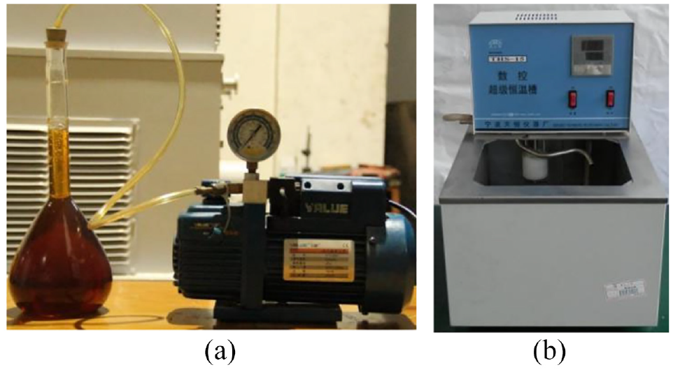
Gas content measurement device: (a) flat bottom flask, vacuum pump and (b) thermostat bath.
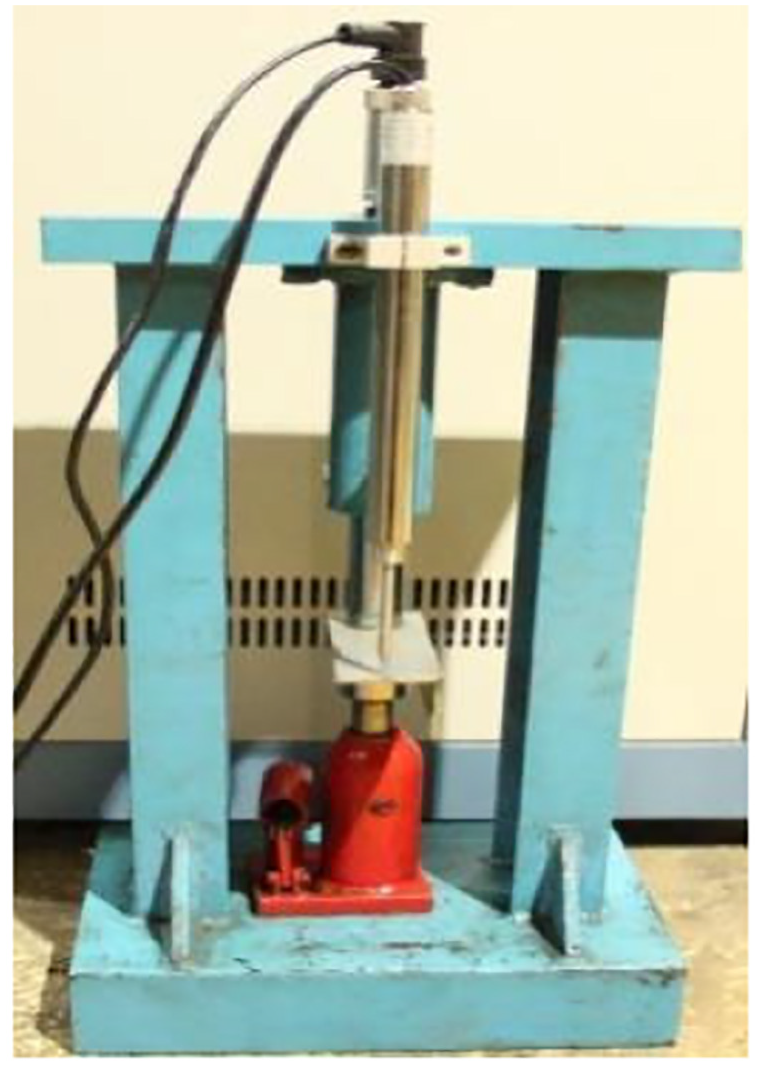
Fluid bulk modulus measuring device.
Figure 5 is the theoretical curve and experiment curve of tangent bulk modulus changing with pressure when the temperature is 90°C and the air content is 0.01 and 0.017 respectively.

The curves of the fluid tangent bulk modulus vary with pressure: (a) air content is 0.01 and (b) air content is 0.017.
It can be seen from Figure 5 that the theoretical results of tangent bulk modulus of oil are basically consistent with the experiment results. When the air content is 0.01, the maximum deviation is 7.17%, and when the air content is 0.017, the maximum deviation is 8.06%. Therefore, the tangent bulk modulus model can accurately reflect the oil bulk modulus during the shift process of HMT closed hydraulic circuit.
Modeling and simulation of closed hydraulic circuit
The principle of two-stage arithmetic type hydro-mechanical transmission is shown in Figure 6, and the following analysis is carried out in this structural form. In the Figure 6, variable displacement hydraulic pump P and fixed displacement hydraulic motor M constitute the hydraulic circuit; planetary gear sets K1, K2,K3 and brakes

Diagram of a two-range HMT.
The range shift logic.

During the shift process of HMT, the functions of the hydraulic components are interchanged, and the high- and low-pressure sides of the closed hydraulic circuit are interchanged. That is, in the H-range, the variable displacement hydraulic pump drives the fixed displacement hydraulic motor, and the outlet of the variable displacement hydraulic pump and inlet of the fixed displacement hydraulic motor are connected with the oil circuit at the high pressure side; after changing to the HM-range, the torque of the fixed displacement hydraulic motor is reversed, the fixed displacement hydraulic motor drives the variable displacement hydraulic pump, and the outlet of the fixed displacement hydraulic motor and inlet of the variable displacement hydraulic pump are connected with the oil circuit at the high pressure side.
In order to study the effect of bulk modulus of oil on the speed of fixed displacement motor during the shifting, the four-cavity model of closed hydraulic circuit is built, and its composition is shown in Figure 7. When modeling, the pressure loss of oil flow along the pipeline is ignored, and the external leakage is considered. The closed hydraulic circuit is simplified into four closed cavities. In the Figure 7, the four-cavity model of the hydraulic circuit consists of the cavity mass flow model and the cavity pressure model.
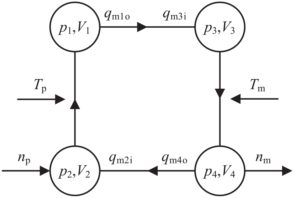
Structure of the four-cavity model.
Speed and torque model of hydraulic components
When shifting from H-range to HM-range, the speed of the variable hydraulic pump is

Where,
The torque balance equation of fixed displacement motor is:

Where,
Mass flow model of cavity
Variable displacement hydraulic pump and fixed displacement hydraulic motor are simplified as external leakage mode. When considering the effect of oil pressure, temperature and air content on oil, the equivalent leakage of hydraulic component is

Where,

Where,
The two hydraulic components work in different modes before and after the HMT shift process, so the mass flow models of the cavity are also different.
(1) Mass flow model of H-range cavity
In H-range, the input mass flow of cavity-2 is

Where,
The output mass flow of cavity-1 is
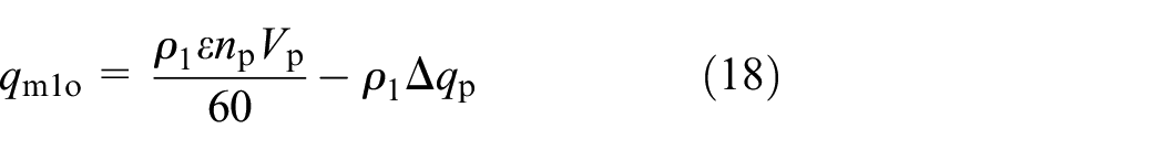
Where,
The input mass flow of cavity-3 is

Where,
The output mass flow of cavity-4 is

Where,
(2) Mass flow model of HM-range cavity
In HM-range, the mass flow relationship between variable and fixed displacement hydraulic components is

Where,
The input mass flow of cavity-3 is

The output mass flow of cavity-4 is

The input mass flow of cavity-2 is

The output mass flow of cavity-1 is

Model of cavity pressure
The oil temperature has almost no change in a short period of the shift, considering the change of bulk modulus, density and air content of the oil in the cavity, the pressure model of the cavity is

Where,
(1) Model of H-range cavity pressure
In the H-range, the cavities 1 and 3 are high-pressure cavities, and the pressure changes of cavities 1 and 3 are:


Ignoring the pressure loss in the high- and low-pressure circuits, the oil pressures in the cavities 1 and 3 are the same, which can be regarded as a whole cavity-5, and its oil pressure model is:

Where,
(2) Model of HM-range cavity pressure
Similarly, in HM-range, the oil pressures of high-pressure cavities 2 and 4 are the same, which can be regarded as a whole cavity-6, and its oil pressure model is:

Where,
The four-cavity model of hydraulic circuit built in Simulink is shown in Figure 8.

Hydraulic circuit four-cavity model in Simulink.
Effect of bulk modulus of oil on shift quality
Based on the four-cavity model of closed hydraulic circuit, different air content is substituted into the bulk modulus model of oil, and the effects of different bulk modulus of oil on the shift quality are simulated and analyzed. When HMT shifts from the H-range to the HM-range, the speed of the variable displacement pump is 1000 rpm, the oil temperature is 90°C, and the pressure at the low-pressure side of the closed hydraulic circuit is 2.55 MPa. The displacement ratio is constant at 0.98, and the load torque from -147 N · m step changes to 99 N · m (Figure 9). The bulk modulus of oil with air content of 0.01, 0.02, 0.03, 0.04, and 0.05 are substituted into the model, and the simulation results are shown in Figure 10. As the effect of air content on the original high- pressure side oil pressure is not obvious, it is not stated here.

Displacement ratio and load torque of the motor.

Simulation results of shift when air content is different: (a) the oil pressure of original low-pressure side and (b) the speed of fixed displacement motor.
Figure 10(a) shows the oil pressure curves at the original low-pressure side with different air content. The higher the air content of the oil is, the greater the fluctuation of the oil pressure is, and the higher the oil pressure of the original low-pressure side of HM-range is.
Figure 10(b) shows the output speed curves of fixed displacement motor with different air content. The larger the air content of the oil is, the greater the fluctuation of the speed is; the greater the difference of the speed before and after the shift is.
It can be seen from the above that the bulk modulus of oil is an important factor affecting the shift quality. In this paper, considering the effect of the bulk modulus of the oil, by precisely controlling the displacement ratio and the slipping time of the two brakes shifting, the fluctuation of the oil pressure at the original low-pressure side is reduced, so that the pressure value of the HM-range is kept at the target value, and the fluctuation of the speed of the fixed displacement motor is reduced, so as to eliminate the speed difference of the motor before and after the shift process.
Lean control model of closed hydraulic circuit shift process
Mathematical model of displacement ratio of variable displacement pump
In H-range, when the pressure in the high-pressure cavity

Where,
In HM-range, when

Where,
The change amount of displacement ratio before and after shifting is:

From the above equation, it can be seen that the smaller the bulk modulus of the oil is, the greater the
In this paper, considering the effect of bulk modulus of oil, the displacement ratio of variable displacement pump is adjusted to improve the shift quality.
Mathematical model of flipping time of two brakes
The shifting time of HMT is the time required from the completely disengagement of the brake
The torque relationship of the sun gear, ring gear and planet carrier in each planetary row is:

where,
According to the structure of HMT in Figure 6, when the two brakes are engaged and overlapped, the expressions of the torque of each planetary row and the torque of brakes and fixed displacement motor are:

Where,
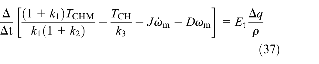
According to the equations (34) and (35), the relationship between the load torque of fixed displacement motor and the torque provided on brakes
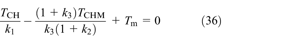
Combining equations (14) and (26), the relationship between the shifting time required for the two brakes and the bulk modulus of the oil is as follows:
It can be seen from the above equation that the larger the bulk modulus of the oil is, the shorter the flipping time of the double brakes is required for the stable output of the speed of the fixed displacement motor; from the relationship between the bulk modulus of the oil and the air content, it can be seen that the larger the air content is, the longer the flipping time of the double brakes is, that is, the longer the shifting time is.
In this paper, considering the effect of bulk modulus of oil, the lean control method of two brakes flipping time was proposed to improve the shift quality.
Effect of the lean control method on the shift quality
When HMT shifts from the H-range to the HM-range, according to the above displacement ratio mathematical model and the two brakes flipping time mathematical model, the displacement ratio and the lean control value of the shifting time are shown in Table 2 below by substituting the oil bulk modulus with the air content of 0.01, 0.02, 0.03, 0.04, and 0.05.
Displacement ratio and shift time.

The data in Table 2 is substituted into the simulation model of HMT hydraulic circuit mentioned in section “Modeling and simulation of closed hydraulic circuit,” and the simulation results are shown in Figure 11.

Simulation results of shift when air content is different: (a) the oil pressure of original low-pressure side and (b) the speed of fixed displacement motor.
Figure 11(a) shows the oil pressure curves of the original low-pressure side. Compared with Figure 10(a), the fluctuations are reduced by 85.29% to 94.9%; through the lean control, the oil pressures of HM-range with different air content are basically consistent with the target value.
Figure 11(b) shows the output speed curves of fixed displacement motor. Compared with Figure 10(b), the speed fluctuations are reduced by 72.95% to 89.58%; through the lean control for different air content, the speed differences before and after the shifting are less than 1 rpm.
When shifting, considering the effect of the bulk modulus of the oil, the reasonable controls of the displacement ratio and the shifting time can effectively reduce the pressure fluctuation in the hydraulic circuit and the speed fluctuation of the fixed displacement motor; keep oil pressure of the original low-pressure side consistent with the target value of the HM-range; keep the motor speed basically unchanged before and after the shifting.
Experiment and analysis of the HMT shift quality
In order to verify the simulation results, an experiment bench for the HMT shifting is built, as shown in Figure 12. The relevant parameters of the main equipment of the bench are listed in Table 3. The control oil source is provided by the pump station. By adjusting the current of displacement control proportional solenoid valve, the displacement ratio of variable displacement hydraulic pump can be adjusted. By controlling the voltage of the solenoid valve of transmission brakes
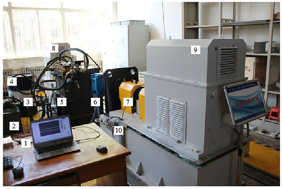
HMT shift test platform.
Parameters of the main equipment of the bench.

Due to the limitation of the experiment condition, the validity of the simulation model and the proposed theory is only verified when the air content is 0.02. In order to facilitate the comparison, the simulation and experimental results are translated on the time axis, so that the starting time of the shifting process is aligned at about 0.25 s.
During the experiment, the speed of variable displacement hydraulic pump is 1000 rpm, the system temperature is constant at 90°C, and the load torque of HMT is 357 N · m. The experiment is started after the oil is stirred for 30 min, and the air content of the oil is 0.02, which can be considered as a constant during the experiment.
When shift from the H-range to the HM-range, the pressure control signals of the two brakes occur step change at the same time, and the oil charging and discharging process of the two brakes does not overlap; control the displacement ratio of the variable displacement hydraulic motor is constant 0.98 (Figure 13(a), and the simulation and experiment results are shown in Figure 13(b)).

Simulation and test curves of the shift progress: (a) displacement ratio and brake control signal and (b) oil pressure and motor speed.
In Figure 13(b), the fluctuation of oil pressure in the original low-pressure oil circuit is 8.786 MPa; the fluctuation of speed of fixed displacement motor is 43.9 rpm, and the speed difference before and after the shifting is 68.2 rpm. The state value and fluctuation value of the simulation curve before and after the shifting are basically consistent with the experiment curve, so the simulation model can describe the shifting characteristics of HMT.
When shifting, the displacement ratio and the flipping time of the two brakes are controlled by the value calculated by the mathematical models in sections “Mathematical model of flipping time of two brakes” and “Effect of the lean control method on the shift quality.” The oil charging and discharging process of the two brakes overlaps; the displacement ratio decreases linearly from 0.98 to 0.9125 (Figure 14(a)), and the simulation and experimental results are shown in Figure 14(b).

Simulation and test curves of the shift process in lean control: (a) displacement ratio and brake control signal and (b) oil pressure and motor speed.
In Figure 14(b), the fluctuation of oil pressure in the original low-pressure oil circuit is 0.92 MPa; the fluctuation of speed of the fixed displacement motor is 8.8 rpm, and the speed difference before and after the shifting is less than 1 rpm. The simulation curve is basically consistent with the experiment curve. Compared with Figure 13(b), the fluctuation of oil pressure wave is reduced by 79.95%; the fluctuation of speed is reduced by 89.53%, and the speed difference before and after the shifting is reduced by 98.54%. Therefore, the lean control of displacement ratio and flipping time of two brakes proposed in this paper is effective when considering the bulk modulus of oil.
Conclusion
In this paper, the closed hydraulic circuit of HMT is equivalent to four cavities, and the mathematical model of closed hydraulic circuit shift process considering the air content of oil is established. The effects of air content of oil on the shift quality are simulated and analyzed. The mathematical model of displacement ratio and the mathematical model of the shift time are established. The effect of displacement ratio and the flipping time of two brakes on the characteristics of the HMT shift is analyzed and experimented. The conclusions are as follows:
Through the verification of the experiment, the tangent bulk modulus model can correctly reflect the bulk modulus of the oil in the shift process of HMT closed hydraulic circuit; when shifting, the bulk modulus of the oil changes greatly, so the effect of the bulk modulus of the oil should be fully considered.
The effect of the bulk modulus of the oil on the shift quality is analyzed. The results show that during shifting, the smaller the bulk modulus of the oil is, the greater the pressure fluctuation of the original low-pressure side is, and the greater the difference between the original low-pressure side and the target value is; the greater the air content is, the greater the speed fluctuation of the fixed displacement motor is, and the greater the speed difference before and after the shifting is. The smaller the bulk modulus of the oil is, the worse the quality of the shift is. The bulk modulus of oil, as an important factor, must be considered when studying the characteristics of HMT shifting process.
The mathematical models of displacement ratio and the shifting time are established, and the lean control method is put forward. The effectiveness of HMT four-cavity model and the lean control method are verified by experiments. It is concluded that the pressure fluctuation of hydraulic circuit and the speed fluctuation of fixed displacement motor can be effectively reduced, the speed difference before and after the shifting can be eliminated, and the shift quality can be improved when considering the oil bulk modulus during the shift process.
Footnotes
Handling Editor: James Baldwin
Declaration of conflicting interests
The author(s) declared no potential conflicts of interest with respect to the research, authorship, and/or publication of this article.
Funding
The author(s) disclosed receipt of the following financial support for the research, authorship, and/or publication of this article: This work was supported by the National Natural Science Foundation of China [Grant number 51675462].