
Abstract
This article takes an efficient feeding head as the research object to study its work mechanism and perform dynamics analysis of the materials in the feeding head. In addition, this article obtains the physical prototype of a three-dimensional model and the feeding surface equation through the surface data of the feeding head and investigates different unfold lines of the feeding surface. In addition, this article recommends a curve equation of the feeding head under different friction coefficients through EDEM + FLUENT simulation analysis and conducts a research on transport and feeding quantity to deduce the equation for the transport quantity of the feeding head. Finally, the verity of the preceding curve equation and transport quantity is confirmed, which has important guiding significance for the feeding head design.
Introduction
The vertical screw conveyor is mainly used for material handling. This conveyor is a kind of continuous conveying equipment, which can be used to transport all kinds of powder, granule, and lump materials with high efficiency, small pollution, simple structure, and high reliability.1,2 With the extensive application of the vertical screw conveyor, the feeding device, which is an important part of the vertical screw conveyor, is also produced in various forms. One of the most important kinds of feeding device is the feeding head, whose feeding rate and efficiency are related to the feed efficiency of the conveyor.
In Sweden, Australia, and other countries, the technology of the vertical conveyor and the feeding head is relatively advanced, which put forward various prototypes of the feeding head, such as reverse rotation feeding head with multiple feed baffles, feeding head with double spiral type, feeding head with spiral baffle, and feeding head with wing plate.3,4 These countries developed the feeding head through tests that measured the filling rate, powder, and productivity of different sizes of feeding head models. Feeding performance indicators, which are dependent on the feeding head structure parameters, are described through the experimental curve, thereby confirming better design variables. The present feeding head technology in our country has no unified standard compared with foreign advanced technology. Each manufacturer has its own defined standards without a unified standard specification (Figure 1).

Three kinds of feeding head.
Feed efficiency and delivery value directly affect the transmission efficiency of the vertical screw conveyor. The main factors affecting the feed rate are the curve surface of the feeding head. Feeding head has various forms, and the curve surface of the feeding head also varies. Therefore, the projection, unfold plate of the curve surface, and shape and equation of the characteristic curve also have their own characteristics. However, material movement and stress in the feed are complex. Thus, discussing the movement process of material in the feeding head is theoretically difficult. An increasing number of tests are employed in the simulation of virtual prototypes due to the development of computer simulation technology. This process reduces costs, improves efficiency, and solves problems in microscopic characteristics, which are difficult to observe in the actual experiment.5,6
There are two kinds of approach to simulate the particle flow. One main approach is the computational fluid dynamics (CFD), and hence, the numerical solving is employed for Navier–Stokes equation. It can be used to model the flow for complex geometries and different properties like viscosity or density. The other approach is discrete element method (DEM). A large of number of discrete particles are simulated whose positions are calculated for each time step based on the acting forces. Feng et al. compared the DEM with the numerical Navier–Stokes approach by simulating a fluid flow, where a good agreement is shown between the two approaches. Sano investigated the DEM-simulated granular flow with and without friction. Renzo investigated the particle forces during collision with other particles.
The real movement of the material cannot be simulated by EDEM software alone and must be combined with FLUENT software because the material in the feeding head is under the influence of air resistance. 7 This study combines theoretical analysis with EDEM + FLUENT simulation to analyze the feeding process and inspect the motion state and transport quantity of the material in the feeding head.
Mechanical analysis
Structure of the feeding head
When the material enters into the feeding window, the radial size of the screw decreases, and the material is forced into the bottom of the screw duct near the center or sprinkled on the screw vane. The high-speed rotation of the screw shaft causes the upward transport of the material, and the screw baffle inclined along the height prevents spillage of the material caused by the centrifugal effect.
Determining the reasonable structure of the feeding head is a research precondition on the working mechanism of the feeding head. The feeding device should have the four following functions. (1) Feeding function. The feeding function is the main functional requirement of the feeding head. The radial size of dig material plate outside of the feed entrance should gradually decrease along the opposite rotating direction of the feeding tube to facilitate the entrance of the material into the feeding window, thereby providing the material with its radial movement component. (2) Preventing splash function. When the material enters into the feeding head, the material rapidly moves along the circumferential of the feeding head due to the high-speed rotation of the screw shaft. The material will splash on to the outside of the entrance under the action of centrifugal force. This splashing phenomenon requires the materials to gain enough pressure to balance the centrifugal force and prevent material spillage. In addition, the pressure of the material is closely related to the structure and size of the guide plate. (3)Tunneling function. The feeding head of the vertical screw conveyor should be able to easily enter the stockpile, and its nose should be able to dig materials around during lateral movement. (4)Feed function. This function must ensure that the feed inlet has plenty of materials and enough pressure to achieve a high picking efficiency. Satisfying such requirement is difficult for illiquid materials due to the influence of gravity. Therefore, the feeding head is required to have some form of a guide plate to force the material flow inlet. The feeding head structure is shown in Figure 2.

Structure of the feeding head.
Figure 2 shows that the feeding head is mainly composed of feeding leaves and windows, and the material enters into the feeding head through the feeding window. The feeding blade comprises digging and guide blades. The digging blade tunnels the material into the feeding head, whose basic shape appears as an unfold surface from the top. This shape is beneficial to the uniform change of friction. The guide blade prevents the material from spilling out of the feeding head due to screw rotation, which plays a guiding role for the material. The digging and guide blades work alone, and the two parts are welded together.
Work mechanism of the feeding head
With regard to the working mechanism of the feeding section of the vertical screw conveyor, the main objective of this study is to analyze the regularity in the process of physical movement in the feeding section. When the feeding head structure is confirmed, performance parameters of the feeding period, such as filling rate, feed value, energy consumption, and efficiency will be based on the structural size of the guide blade and speed of the feeding head. Thus, establishing the mechanism of the material motion model of the materials from a motion to a stress state in the feeding section is necessary.
The motion process of the material in the feeding head is very complicated. This process can be divided into the digging process of the digging blade of the feeding head, the accelerated process of the material as it enters into the feeding head, and upward transportation process of the material when the screw axis and the feeding head are counter-rotating.
Digging process of the digging blade. Owing to the radial size of the digging blade, which gradually decreases along the reverse rotation direction of the feeding head, the material with radial motion component enters the delivery pipe or outside of the feeding head through the feeding window.
Accelerated process of the material entering into the feeding head. After the material enters into the feeding head, the motion state of the material rapidly changes in a short period of time due to the high-speed rotation of the screw in the conveyor pipe. After the material undergoes the accelerated process in the circumferential and spiral line directions and the wall, the material obtains projectile motion with a certain initial velocity, thereby falling into the bottom of the feeding head with stacking states. The circular movement of the screw, in turn, pushes the material inside the bottom of the feeding head and speeds up material movement in a very short time along the circumferential direction and rotation with the screw. The material continuously moves into the feeding head and comes in contact with the stockpile formed on the screw surface. The momentum of the material on the particle rapidly increases because the stockpile rotates with the screw, thereby allowing material movement on the heap with the stockpile.
Upward transportation process of the material. In the feeding period of the screw conveyor, when the feeding head and screw axis rotate in reverse direction in different angular velocities, the material in the screw tube wall under the action of friction of the screw blade and tube wall slides generate slide relative to the screw blade, and the material with the movement of the vertical component can facilitate delivery.
This study focuses on the relative rotary feeding head whose feeding head rotates reversely with the screw shaft. This feeding head can force material into the vertical screw conveyor using the inclined feed blade. In addition, it can prevent the material from being thrown due to the centrifugal force produced by the high-speed revolution of the screw and increase the filling rate of the vertical screw conveyor. In the event of material blockage, the reverse screw can spit the material out.
Dynamics analysis of material feeding
Owing to the gradual decrease in digging blade radial size during the reverse rotation direction of the feeding head, the material with radial motion component enters the delivery pipe or outside of the feeding head through the feeding window. The difference between the screw shaft and the feeding head will lead to different stress states, and the material in the feeding head may be under two kinds of motion state, that is, relative movement into the conveyor pipe along the digging blade or relative movement outside of the conveyor pipe along the digging blade. The feeding head is composed of three feeding windows and three feeding blade. When the feeding head functions, the feeding blade stirs the material and forces it into the feeding head through the feeding window. The air inside the feeding head is generated because of the high-speed rotating spiral blade, which will obstruct material flow due to the closed environment of the feeding head. Consequently, the material inside the feeding head is also affected by the air resistance.
Take the dispersed particle m whose distance from the screw shaft is r as the analysis object, with the rotation movement of the feeding head as the implicated movement and the relative motion m relative to the feeding blade as the relative movement, to build

Dynamics analysis of the material entering into the feeding head.

Dynamics analysis of the material splash from the feeding head.
According to the relative motion dynamics of particles, the basic equation for relative motion dynamics of m is as follows

where a is the acceleration of the particle relative to the screw blade, F is the resultant force of particles under the external force, which includes the gravity mg, normal force of the digging blade
As shown in Figures 3 and 4, the absolute motion of particles
Determining particle speed using the traditional method of Newton’s second law of motion is difficult due to the complexity and uncertainty of external force that the particle suffered. Therefore, the simulation analysis method is used to observe changes in particle speed. The transport quantity of the feeding head comprises materials into and out of the feeding head. More material flowing into the feeding head and less material outflow from the feeding head will lead to more transport quantity. This transport quantity depends on the screw speed and feeding head speed and structure, while the structure of the feeding head depends on the surface size of the guide blade of the feeding head.
Surface of the feeding blade
Curve equation of the surface
The surface data of an efficient feeding head are achieved through reverse engineering,8,9 which is used to obtain the three-dimensional (3D) model of the physical prototype and an expanded view of the feeding surface.
Figure 5 shows the 3D model of a single feeding surface of the guide blade.

The 3D model of single feeding surface of guide blade: (a) planform and (b) left view.
Figure 6 shows the sketch of the top view of the single feeding surface of the guide blade. The connection between the curve and the center achieves the maximum, whose point edge the curve in q1 and q2. Choosing the angle

Sketch for top view of single feeding surface of guide blade.
Using the MATLAB software, the equation is fitted to the characteristic curve of the feeding surface of the guide blade, in which the curve achieved is an Archimedean spiral set as curve 3. The curve equation is


The preceding curve is in the radius of the 358 mm feeding mouse, where the feeding area is proportional to the curve; hence, the radius of the feeding mouse is also proportional to the curve. Setting the radius of the feeding mouse as R, the fitting curve of q1 is as follows

The fitting curve of q2 is as follows

Change the value of b of the Archimedean spiral to observe the feeding state of different curves. Based on curve 3, the unfold lines are gradually increased at 10 and 20 mm to obtain curves 2 and 1, respectively. Based on curve 3, the unfold lines gradually decreased at 10 and 20 mm to obtain curves 4 and 5, respectively. The order of unfold lines from big to small is as follows: curves 1, 2, 3, 4, and 5. Figure 7 shows the curve graph of q1 and q2 of all kinds of curves.

Curve graph of q1 and q2 of all kinds of curve.
The equations of all curves are as follows
Curve 1

Curve 2

Curve 3

Curve 4
Curve 5
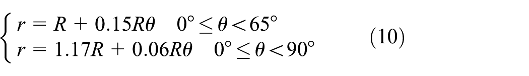
Figure 8 shows the sketch of left view of the single feeding surface of the guide blade.
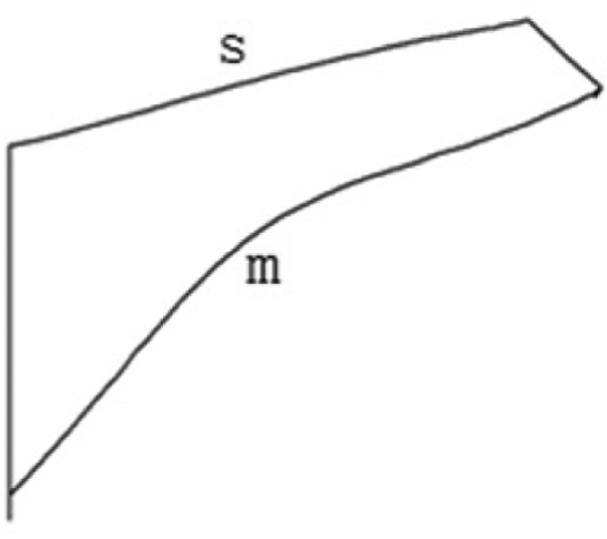
Sketch of left optic of single feeding surface of guide blade.
Curves s and m are the upper and lower curves of the guide blade, respectively, and the fitting function of curves m and s is obtained by fitting, as shown in Figures 9 and 10, respectively
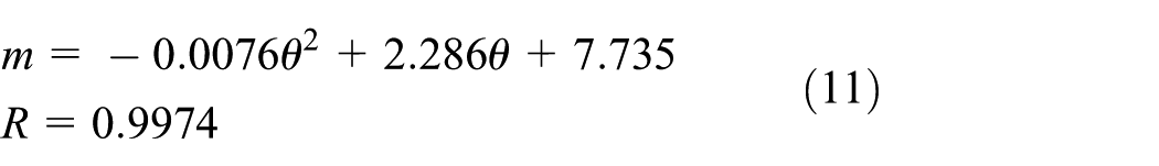


Fitting function of curve m.

Fitting function of curve s.
Set curve s and curve m of the guide blade invariant and compose five different curve surfaces with five preceding curves. And then, analyze the particles in the feeding head under five curve surfaces.
Model building
The material in the feeding head suffered the influence of air resistance; thus, the states of the particles in the feeding head are analyzed by using EDEM software coupled with FLUENT software. In Figure 11, the model, which has a screw diameter of 200 mm, a feeding mouth diameter of 240 mm, and three feeding windows, is built. The preceding model mentioned is built in SOLIDWORKS software and imported into the EDEM software. Then, the model is combined with FLUENT software for EDEM + FLUENT simulation analysis to obtain the state of particles in the feeding head considering air resistance. The Reynolds stress model was used to deal with the gas flow field.
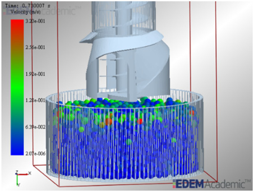
Simulation model of feeding head.
Figure 10 shows the construction of the simulation model. Figure 12 presents the feeding states of the feeding head in 1, 1.5, 2, and 2.5 s.

Feeding states of the feeding head in (a) 1 s, (b) 1.5 s, (c) 2 s, and (d) 2.5 s.
In Figure 12, when the simulation is running at 2 s, the feeding head is embedded into the material heap. Then, the particle begins conveyance along the screw, and the feeding head starts a steady upward transportation movement.
Table 1 shows various simulation working conditions. These particles are spherical and unbreakable, whose material property is shown in Table 1.
Various simulation working condition of the feeding head.
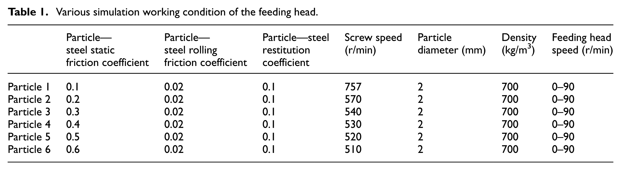
As shown in Table 1, a total of six kinds of particle feeding states in different static friction coefficients, whose feeding speeds are 10, 20, 30, 40, 50, 60, 70, 80, and 90 r/min, are analyzed, and the screw speed in the pipe is obtained according to the definition of the best screw speed documented. 7
Best surface
The five preceding kinds of curve surfaces mentioned are investigated using EDEM + FLUENT simulation analysis, and the transport quantity of different curve surfaces at different friction coefficients is compared.
Figure 13 shows the transport quantity of five curve surfaces at different rotational speeds of the feeding head when different friction coefficients exist between the material and the feeding head.

Transport quantity of five kinds of curve surface at different friction coefficients: (a) µ = 0.1, (b) µ = 0.2, (c) µ = 0.3,(d) µ = 0.4, (e) µ = 0.5, and (f) µ = 0.6.
With the increase in friction coefficient between the material and feeding head, using a large unfolded curved surface is recommended because a large friction coefficient leads to a significant friction force suffered by the material from the feeding head and a small amount of material splash from the feeding mouth. The input quantity of a large unfolded curved surface is larger. However, the large unfolded curved surface can also easily cause material splashing out of the feeding window. Thus, the transport quantity of the maximum unfolded curved surface 1 is not bigger than surface 2. Using curved surface 1 is not recommended in any friction coefficient. With the decrease in the friction coefficient between the material and feeding head, using a small unfolded curved surface is recommended because a small friction force suffered by the material from the feeding head leads to a large material splash from the feeding window. Hence, a small unfolded curved surface is better than a large one. However, the small unfolded curved surface decreases the quantity of material entering into the feeding head. Therefore, the transport quantity of the minimum unfolded curved surface 5 is not greater than that of surface 4, and using curved surface 5 is not recommended in any friction coefficient.
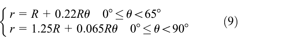
Thus, using different guide blade surfaces under different friction coefficients is recommended, which can be concluded as follows: when
Transport quantity
Feeding area
By the dynamics analysis of material feeding

where
The feeding quantity

where

where
Therefore, the feeding quantity of the feeding head is as follows

Figure 14 shows a single feeding area. The structure centerline of the vertical pipeline is DE; AE is the ligature of the end point of q1 A, center E, and attachment AD. The curve m of the feeding head comprises a section, which is defined as the feeding area of the feeding head and is regarded as a ladder.

Single feeding area.
DE is the radius of the feeding mouth, AE is the curve value of q1 when the angle
By the curves m, q, and s, the feeding areas of five different kinds of curves are as follows (Table 2).
Feeding area of five different kinds of curves.

Transport quantity
Set
When the friction coefficient is 0.1 and 0.2, surface 4, whose feeding area can be calculated as 0.015529 m2, is selected. When the friction coefficient is 0.3, 0.4, and 0.5, surface 3, whose feeding area can be calculated as 0.016115 m2, is selected. When the friction coefficient is 0.6, surface 2, whose calculated feeding area is 0.016848 m2, is selected. The feeding quantity can be calculated using equation (16) under different feeding speeds and compared with the simulation values of transport quantity. Figure 15 shows the comparison chart between the feeding quantity and transport quantity which can be obtained from different friction coefficients.

Comparison chart between feeding quantity and transport quantity under different friction coefficients: (a) µ = 0.1,(b) µ = 0.2, (c) µ = 0.3, (d) µ = 0.4, (e) µ = 0.5, and (f) µ = 0.6.
In Figure 15, with the increase in the friction coefficient, the gap between transport quantity and feeding quantity decreases, that is, the splash quantity is reduced with the increase in friction coefficient.
From equation (16), the feeding quantity is a linear relationship with the feeding speed under the same friction coefficient and curve. Set
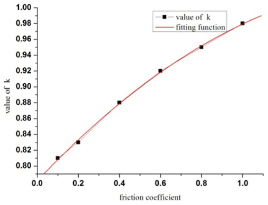
Value of k under different friction coefficients.
The fitting function is

So, the transport quantity is

where
When the transport quantity of the vertical screw conveyor is known, according to equation (18), the rotational speeds of the feeding head are

Experimental verification
Test rig for the vertical screw conveyor
We set up an efficient vertical screw conveying test bench (Figure 17) to verify the correctness of the preceding methods mentioned.
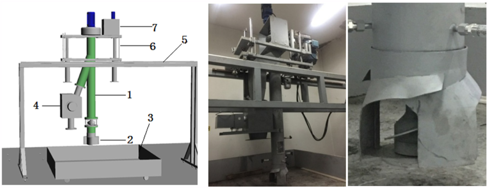
Efficient vertical screw conveying test bench.
The experimental process is mainly detailed as follows. The vertical screw conveyor is installed in the middle of the movable double-beam gantry, which can be shuffled with adjustable speed by car. This car can go up and down by carriage and fixed frame and move back and forth by mobile double-beam gantry. This system enables the vertical screw conveyor to move around to feed particles. The mobile chute is used for holding the discharge material during measurements. The screw rotates through the drive device and feeds at the bottom rotation in reverse fashion. The material served on the mobile is taken into the vertical screw conveyor for vertical transmission. The vertical screw conveyor is 1.2 m long, with a long glass in the middle section allotted for the high-speed camera that measures particle velocity. The diameter of the screw blade is 0.2 m, and the screw speed can reach 45–600 r/min with adjustable speed. The screw pitch is 0.1 m, and the tube wall of the screw conveyor is steel. The bottom of the vertical screw conveyor is sleeved by screw feeding, with an open wide import face. The feeder is driven by independent screw feeding at an adjustable feeding speed of 5–200 r/min.
The test rig can measure the transport quantity in the vertical screw conveyor under different screw speeds, materials (friction coefficient), and feeding head speeds, whose transport quantity can be measured by DE20 flow meter of bulk material of the blunt plate and can be easily installed under the discharging place of the vertical screw conveyor, as shown in Figure 18.

Flow meter of bulk material of blunt plate.
Results and analysis
Wheat, coal ash, and dry sand, whose bulk densities are 0.7, 0.7, and 1.6 t/m3 and whose friction coefficients are 0.3, 0.4, and 0.5, respectively, are tested. According to the transport quantity defined in the literature, 7 when the screw radius is 100 mm, the bulk density of the material is 0.7 t/m3, the friction coefficient is 0.3, and the calculated transport quantity is 61 t/h, which is generated from equation (19) where the calculated feeding head speed is 46 r/min. Furthermore, when the bulk density of the material is 0.7 t/m3, the friction coefficient is 0.4, and the calculated feeding head speed is 41 r/min. When the bulk density of the material is 0.7 t/m3, the friction coefficient is 0.5 and the calculated feeding head speed is 39 r/min. Equation (18) is used to compare the transport quantity measured in the experiment with the transport quantity calculated in equation (18) and the transport quantity simulated in EDEM + FLUENT, as shown in Table 3.
Comparison chart between transport quantity in experiment and calculated transport quantity and simulated transport quantity.
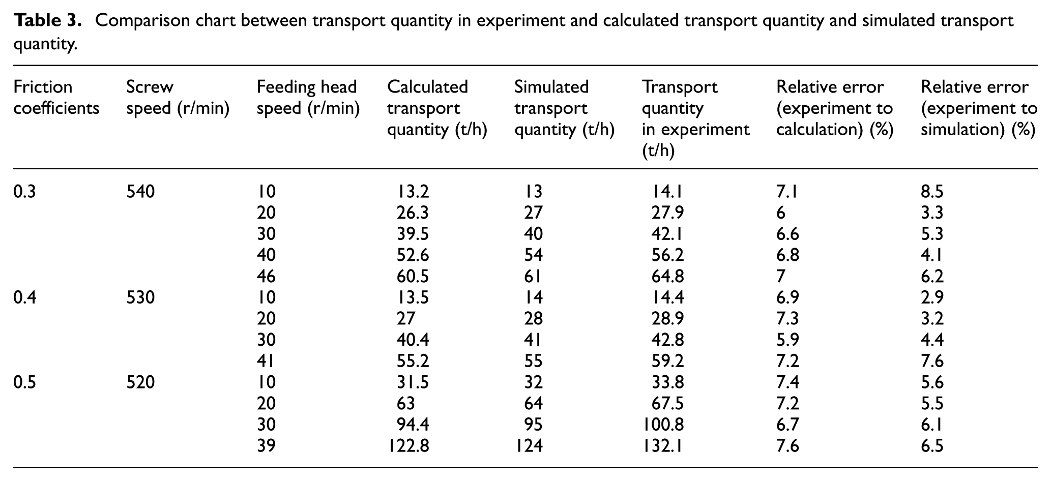
In Table 3, the relative error between the test and calculated values of the transport quantity is approximately 7% where the error is relatively small, thereby verifying the accuracy of the transport quantity in equation (18) and the feeding head speed in equation (19). The relative error between the test and simulated values of the transport quantity are also relatively small, thereby verifying the accuracy of EDEM + FLUENT simulation and also verifying the validity using different guide blade surfaces recommended under different friction coefficients.
Conclusion
The working mechanism and dynamics analysis of the feeding head with relative rotation are studied in this article. An effective feeding head was used as the research object to study the curve equation of five kinds of guide blade surfaces of the feeding head. Particle state in the feeding head was also analyzed through EDEM +FLUENT simulation, and the transport quantities of different surfaces under different friction coefficients were compared, which obtained the recommended guide blade surface of the feeding head under different friction coefficients.
This article analyzes the transport and feeding quantities in the feeding head and calculates five kinds of feeding areas of the feeding window of the curve surface. Transport and feeding quantities under different friction coefficients were compared through EDEM + FLUENT simulation to derive the equation for the transport quantity of the feeding head and obtain the equation for feeding head speed. These parameters have important significance to the design of feeding head.
Footnotes
Handling Editor: Yangmin Li
Declaration of conflicting interests
The author(s) declared no potential conflicts of interest with respect to the research, authorship, and/or publication of this article.
Funding
The author(s) disclosed receipt of the following financial support for the research, authorship, and/or publication of this article: This research was supported by the National Natural Science Fund Project under Grant No. 51575370, the Scientific and Technological Innovation programs of higher education institutions in Shanxi under Grant No. 2017160, and the Shanxi Jincheng Science and Technology plan project under Grant No. 201501004-7, and the Fund for Shanxi “1331 Project” key Subjects Construction.