
Abstract
The cyber-physical system is the core concept of Industry 4.0 for building smart factories. We can rely on the ISA-95 architecture or the 5C architecture to build the cyber-physical system for smart factories. However, both architectures emphasize more on vertical integration and less on horizontal integration. This article proposes the 8C architecture by adding 3C facets into the 5C architecture. The 3C facets are coalition, customer, and content. The proposed 8C architecture is a helpful guideline to build the cyber-physical system for smart factories. We show an example of designing and developing, on the basis of the proposed 8C architecture, a smart factory cyber-physical system, including an Industrial Internet of Things gateway and a smart factory data center running in the cloud environment.
Introduction
The cyber-physical system (CPS) is the core concept of Industry 4.0 advocated by the German government for building smart factories to bring about the fourth industrial revolution. The term CPS was first introduced in 2006, when an National Science Foundation (NSF) workshop was held in Austin, Texas, USA. 1 It was defined as “a system composed of collaborative entities, equipped with calculation capabilities and actors of an intensive connection with the surrounding physical world and phenomena, using and providing all together services of treatment and communication of data available on the network.” 2 The CPS has attracted a lot of research attention. In addition to smart factories, many CPS-based applications have been built, such as healthcare, 3 smart grid, 4 smart transportation, 5 smart home, 6 smart buildings, 7 and smart cities. 7
We can rely on the ISA-95 architecture,
8
which is proposed by the International Society of Automation (ISA), or the 5C architecture,
9
which is proposed by Lee et al. to build the CPS for smart factories. The ISA-95 architecture divides the system into levels 0–4. The following is the description of those levels quoted from Brandl:
10
Level 0 defines the actual physical processes. Level 1 defines the activities involved in sensing and manipulating the physical processes. Level 2 defines the activities of monitoring and controlling the physical processes. Level 3 defines the activities of the workflow to produce the desired end-products. Level 4 defines the business-related activities needed to manage a manufacturing organization.
The 5C architecture consists of five levels; from bottom to top, they are the connection, conversion, cyber, cognition, and configuration levels. The connection level is concerned with obtaining the accurate and reliable measurement of the production machines by connecting sensors to machines. The conversion level pays attention to the conversion of the measurement data into information. The cyber level emphasizes that more information can be obtained through connecting more machines into machine networks. The cognition level provides users with visual and statistics information to assist them to make decisions. The configuration level finally gives feedback back to the physical system according to the decisions made.
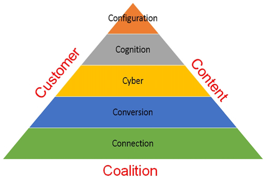
Both the ISA-95 and the 5C architectures emphasize more on vertical integration and less on horizontal integration. In view of this, we propose, in this article, the 8C architecture by adding 3C facets into the 5C architecture. The 3C facets are coalition, customer, and content. The coalition facet focuses on the value chain integration and production chain integration between different parties in terms of the production process. The customer facet focuses on the role that the customers play in the production process. The content facet focuses on extracting, storing, and inquiring all contents related to products, such as the design, the manufacturing parameter, the product traceability record, and the after-sales service record.
The proposed 8C architecture is a helpful guideline for us to build the CPS for smart factories. We show an example of developing a smart factory CPS (SF-CPS), including an Industrial Internet of Things (IIoT)11,12 gateway and a smart factory data center, running in the cloud, 13 on the basis of the proposed 8C architecture. In this example, we can see how sensor and actuators are connected to machines and how sensed data are converted into information. We can also see how sensed data are aggregated together for better data analytics, such as clustering for similarity in data mining, how they are properly visualized for remote and collaborative decision making, and how the CPSs are self-configured for resilience. Furthermore, we can see how different parties are integrated together, how the role of customers is emphasized, and how product content is extracted, stored, and inquired.
This article is organized as follows. In section “Related work,” we elaborate on two CPS reference architectures, namely, the ISA-95 architecture and the CPS 5C architecture. Section “Proposed CPS 8C architecture” presents the proposed CPS 8C architecture and section “Development of a CPS based on the 8C architecture” demonstrates an example of developing a SF-CPS, including an IIoT gateway and a smart factory data center running in the cloud, on the basis of the proposed 8C architecture. Finally, section “Conclusion” concludes the article.
Related work
ISA-95 architecture
The American National Standards Institute (ANSI) ISA-95 architecture or the S95 architecture 8 was approved by ISA for the purpose of enterprise-control system integration. It is also known as the IEC/ISO 62264 standard. It has levels 0–4, as shown in Figure 1. Below are the descriptions of the levels:
ISA-95 levels 0 and 1. Level 0 is the physical production process, while level 1 is for sensing and manipulating the production process by sensors and actuators.
ISA-95 level 2. Level 2 is for the monitoring, supervisory control, and automated control of the production process. Possible entities at this level are the supervisory control and data acquisition (SCADA) system, distributed control system (DCS), and programmable logic controller (PLC).
ISA-95 level 3. Level 3 deals with workflow and activities to produce the desired products. Possible entities at this level are the manufacturing execution system (MES), production information management system (PIMS), warehouse management system (WMS), and computerized maintenance management system (CMMS).
ISA-95 level 4. Level 4 is concerned with running an enterprise. It is devoted to business-to-manufacturing (B2M) transactions. It deals with business planning, logistics, production scheduling, operational management, managing commercial activities, and product development. Possible entities in this level are enterprise resource planning (ERP), product lifecycle management (PLM), human resource management (HRM), customer relationship management (CRM), and supplier relationship management (SCM) systems.

The ISA-95 (S95) architecture. 8
CPS 5C architecture
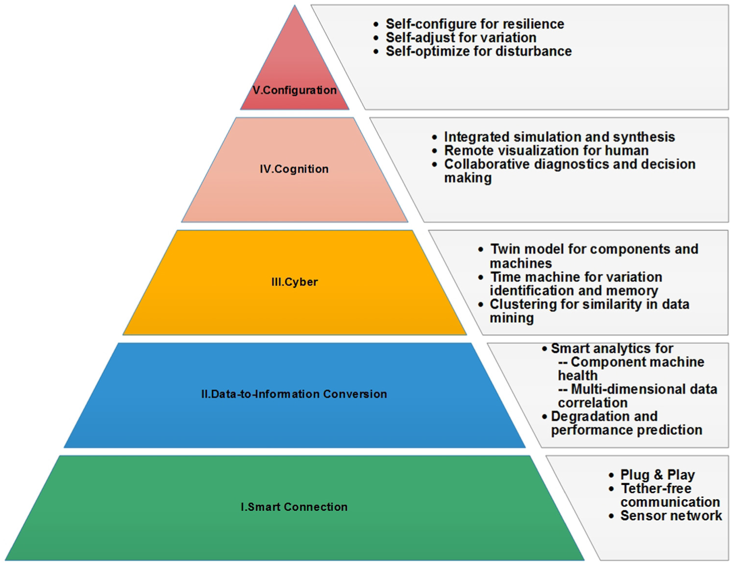
The CPS 5C architecture, proposed by Lee et al. 9 to build the CPS, consists of five levels, namely, the connection, conversion, cyber, cognition, and configuration levels (Figure 2). Below we describe the details of each level:
Connection. As mentioned in Lee et al., 9 connecting machines and their components for acquiring accurate and reliable data is the first step in developing a CPS for smart factories. Different devices or sensors are used to acquire a variety of data, including voltage, current, temperature, vibration, rotating speed, feed speed, and oil concentration of machines and their components, as well as images and videos of workpieces during manufacture. Sensors can also be installed for acquiring phenomenal data of the manufacturing field and warehouse, like temperature, humidity, lightness, and atmospheric pressure. Data may also come from the PLC, programmable automation controller (PAC), or manufacturing systems, such as the ERP, MES, SCM, and coordinate measuring machine (CMM) systems. Specific protocols, such as those used in the IIoT technology, are used to realize data transfer and management.
Conversion. As stated in Lee et al., 9 data are converted into information at this level. Several mechanisms can be used to realize the data-to-information conversion. For example, some mechanisms are developed to convert data into useful information, and even predictive information, such as the health value and remaining useful life (RUL) value, which can be used in machine prognostics and machine health management. This level brings the self-awareness property to the machines.
Cyber. The cyber level plays the role of a central information hub, which gathers massive information from machines in the machine network. At this level, extra analytic information is extracted from the gathered information to provide better understanding of individual machines. By the information, the performance of a single machine is compared and ranked among all machines in the network. Furthermore, historical information of machines can be applied to similar machines for future behavior prediction.
Cognition. At this level, proper presentation of analytic information is provided to users for making decisions. This level makes possible remote and collaborative diagnostics and decision making. The priority of tasks for the maintenance process can be easily determined due to the availability of comparative information and individual machine status.
Configuration. The configuration level gives feedback back from the cyber part to the physical part. This level performs the supervisory control for making machines self-configured, self-adjusted, and self-optimized. It acts as the resilience control system (RCS) to apply the controls corresponding to the decisions made in the cognition level to the monitored machines.
The CPS 5C architecture. 9
Proposed CPS 8C architecture
Below we describe the proposed CPS 8C architecture, as shown in Figure 3. The CPS 8C architecture is achieved by adding the 3C facets into the CPS 5C architecture. The 3C facets are coalition, customer, and content. They emphasize the horizontal integration of the CPS, such as the integration (or coalition) of different parties and their associated information (or content). They also emphasize the most important party, namely, the customer, in the manufacture process. Below, we describe the three facets one by one:
Coalition. This facet focuses on the value chain integration and production chain integration among different parties involved in the production process. Different parties can jointly build the supply chain and can co-schedule production lines to form the production chain in order to yield specific products in a flexible and timely way. If there is any adjustment in the production process, different parties may jointly reconstruct the supply chain and production chain dynamically and timely.
Customer. This facet focuses on the role which the customers play in the design process, production process, and after-sales service of the product. Future smart factories can accept various orders with small quantities from a variety of customers and fulfill the orders timely. The customers, either agency/wholesaler or individual buyer, can participate in designing the product, keep track of the progress of the product, and even modify the product specifications during the production process. This can be achieved by the concept of product-centric manufacturing. That is, the factory can spontaneously respond to the product order by automatically preparing materials, flexibly scheduling production processes, dynamically reconfiguring production lines, and automatically arranging storage and delivery for the product. In this way, both mass customization and mass production can be realized. Customers can even be notified of the production progress by receiving email or text messages. The considerations in the customer facet can respond to the shift from the conventional “mass production” paradigm to the newly emerging “mass customization” paradigm. The former paradigm is for producing a large number of products of the same specification, while the latter is for producing a variety of products of different specifications. Furthermore, after the product is delivered, the customers can continue obtaining after-sales services about operating, using, maintaining, and even recycling of the product for better quality of experience.
Content. This facet focuses on extracting, storing, and inquiring the product traceability record. All production information, such as raw material suppliers/sources, production processes, production environment phenomena (e.g. temperature, humidity, vibration), production parameters, warehouses, and production shipment, is extracted and stored properly as product traceability records for future inquiries. All after-sales service details, such as maintenance, parts replacement, and operation instructions guidance, are regarded as important content and stored timely and properly in product traceability records. Moreover, all customer-related after-sale service details, such as product maintenance, parts replacement, troubleshooting, recycling, and the complaints, suggestions, and comments of users, in the form of text, audio, or even video, are regarded as important data and are properly stored. The considerations in the content facet can help achieve the product whole lifecycle service. Certainly, by analyzing all the stored data, not only the manufacturing process, the production design, and the customer service can be improved, but also the product market trends can be predicted.
The proposed CPS 8C architecture.
In summary, the 5C architecture has five levels, while the 8C architecture has three extra facets. With the three extra facets, the 8C architecture focuses on both the vertical and horizontal integration. It is good for both mass production and mass customization, and emphasizes the product whole lifecycle service. Table 1 shows the comparisons of the 5C architecture and the 8C architecture for the purpose of clarifying the difference between the two architectures.
The comparisons of the 5C architecture and the 8C architecture.

Development of a CPS based on the 8C architecture
Below we show an example of designing and developing a CPS based on the 8C architecture for a smart factory of wire electrical discharging machines (WEDMs) produced by the Ching Hung Machinery and Electric Industrial Corporation (CHMER). 14 As shown in Figure 4, the CPS includes an IIoT gateway and a smart factory data center running in the cloud environment.

A smart factory CPS (SF-CPS) based on the CPS 8C architecture.
The WEDM 15 is broadly used in precisely machining a conductive workpiece along a programmed path to cut very intricate and delicate shapes, regardless of workpiece hardness and toughness. Workpiece material is eroded by a series of discrete sparks between the workpiece and a thin wire electrode (tool), which are both immersed in dielectric liquid (deionized water) for the purpose of cooling and flushing away material debris. A suitable gap (0.025–0.5 mm) 16 is maintained between the wire and the workpiece. When an electric pulse is applied to the wire to make the gap voltage exceed the breakdown voltage, a high-power spark is produced and the temperature in the gap zone is increased to about 8000°C–10,000°C. 16 Such temperature melts and vaporizes a very tiny amount of workpiece material, so the WEDM can achieve very low surface roughness (less than 0.2 µm of average roughness, Ra). 17 The wire is held between the upper and lower diamond guides with a specific tension, unwound from a spool, fed through the workpiece, and then wound to another spool. The performance of WEDM is usually measured by the cutting speed, surface roughness, and dimension accuracy of the workpiece. The machining parameters, such as the pulse-on time, pulse-off time, wire feed speed, wire tension, peak current, servo voltage, and dielectric fluid concentration, are the major parameters affecting the performance.
The WEDM SF-CPS is designed and developed with the considerations of the connection, conversion, cyber, cognition, and configuration levels, as well as the coalition, customer, and content facets. Later, we will describe the implementation considerations about the cloud running the data center.
Below, we start describing the design and development from the connection level. Before the description, we first refer the reader to Table 2 to see the major functionality of the WEDM SF-CPS shown in the cyber category and the physical category.
The major functionality of the WEDM smart factory CPS in the cyber category and the physical category.

WEDM: wire electrical discharging machine; CPS: cyber-physical system; NoSQL: Not Only Structured Query Language; RFID: radio-frequency identification; BLE: Bluetooth Low Energy; PAC: programmable automation controller.
In the connection level, two devices, namely, a radiofrequency identification (RFID) tag 18 and a Bluetooth Low Energy (BLE) beacon, 19 are attached to a fixture or a jig for keeping track of the workpiece fixed on the fixture. The RFID tag and the BLE beacon have the same ID, which is representative of the workpiece ID and can be read by an RFID reader or the Bluetooth (BT) reader. After obtaining the ID from the RFID tag or the BLE beacon, the readers forward the ID to the IIoT gateway. Note that the strength of the signals sent by the RFID tag and the BLE beacon is also forwarded to the IIoT gateway for the purpose of positioning the fixture, as will be described later.
Some sensors are embedded in the WEDM to monitor internal machine states, such as the pulse-on time, pulse-off time, wire feed speed, peak current, and servo voltage. The internal machine state data are gathered by a computer-based PLC or PAC and then sent to the IIoT gateway, which is connected to a cloud where the main component of the CPS (i.e. the SF-CPS Data Center) is running. The PAC and the IIoT gateway communicate via the GLink module, developed by CHMER. Some other sensors are embedded to monitor the external machine states, such as the dielectric fluid concentration and the surrounding environment temperature. For example, a capacitive sensor with two parallel conductive planes is designed and implemented to measure the dielectric fluid concentration or turbidity. 20 The sensor can successfully measure the dielectric fluid concentrations of materials like alumina powder, silicon powder, iron powder, and carbon powder. The sensor transmits the sensed fluid concentration data to a BT reader to forward the data to the IIoT gateway.
In the conversion level, the data are then converted into information. For example, the ID and the signal strength of the RFID tag and the BLE beacon, along with the accurate reader position data, can be converted into position information of the workpiece attached on the fixture by indoor positioning algorithms. Later, we will show an algorithm implemented in the CPS to figure out accurate workpiece position information of the fixture out of the gathered data.
On the one hand, the data–information conversion can be realized at the RFID reader, BT reader, PLC, or gateway as long as enough computing resources are available in it. This is actually the concept of fog computing, which is defined in Conde et al. 17 as “an architecture that uses one or more collaborative multitude of end-user clients or near-user edge devices to carry out a substantial amount of storage, communication, control, configuration, measurement and management.” On the other hand, the conversion can be carried out at the cloud side which is abundant in computing resources. In general, if the computing is closer to the data source, the converted information is more timely. Oppositely, if the computing is closer to the cloud site, then we can obtain more in-depth and comprehensive information, as the cloud site has more powerful computing resources and more widely gathered data.
The cyber level is then realized with the help of the network protocols to form networks of machines. Many IIoT protocols can be used for networking machines, such as the Message Queuing Telemetry Transport (MQTT) protocol 21 and the Constrained Application Protocol (CoAP) protocol. 22 In our CPS implementation, we apply the MQTT protocol in the cyber level. The MQTT protocol is a client–server, publish–subscribe messaging protocol atop the Transmission Control Protocol/Internet Protocol (TCP/IP) protocol. It is open, simple, and lightweight; it is thus ideal for constrained communication environments. There are three types of entities in the MQTT protocol: the broker server, the client publisher, and the client subscriber. A publisher performs publications by sending the broker messages on specific topics (or subjects), and a subscriber performs subscriptions by registering with the broker for some topics. The broker matches publications to subscriptions so that a message with a specific top is delivered to all subscribers registering for the top. We install Mosquito, an MQTT message broker, in our IIoT gateway and install message publisher client in the RFID reader and BLE reader to send ID messages on the ID topic. We also install a message subscriber client in the gateway to receive ID messages, along with other messages on different topics, such as machine voltage and vibration. The gateway then forwards the received messages (data) to the SF-CPS data center at the cloud side, so that a twin model for machines is established, a machine network is formed, and data of all machines are aggregated, monitored, and controlled. The MES, PIMS, WMS, and CMMS can be set up at this level.
The cognition level is also realized at the cloud side. At this level, integrated simulation and synthesis are performed. And visual charts are generated at this level to be provided to the users to make collaborative diagnosis and decisions. Currently, we provide simple browser user interfaces (Web UI) and augmented reality user interfaces (AR UI), as shown in Figures 5–11, for users to visualize information. There are the machine overview and the fixture overview in the Web UI. The machine overview shows information about all machines (see Figure 5), while the fixture overview shows information about all fixtures (see Figure 6). When the users click on one of the machines listed in the machine overview, information about the clicked machine (e.g. manufacturing parameters and machine states) will be shown promptly (see Figure 7). Similarly, when users click on one of the fixtures listed in the fixture overview, information about the clicked fixture, such as the ID of the attached RFID tag and the BLE beacon device, the fixture status (e.g. being processed at a certain machine or being put aside at a specific position in the factory), and even the manufacturing traceability report (e.g. raw material supplier, manufacturing parameters, and production states) will be shown promptly (see Figure 8). Our Web UI lacks the interface showing statistics diagrams. We are now planning to apply an off-the-shelf software, the Advantech WebAccess 23 —a web-based human–machine interface (HMI)/SCADA, to achieve better visualization interfaces. Figures 9–12 show some demonstration interfaces provided by the software.

The machine overview in the Web UI.

The fixture overview in the Web UI.

Detailed information of a machine.

Detailed information of a fixture.

Visualization interface screenshot 1 of WebAccess. 15

Visualization interface screenshot 2 of WebAccess. 15

Visualization interface screenshot 3 of WebAccess. 15

Visualization interface screenshot 4 of WebAccess. 15
As shown in Figure 13, there are two modes in the AR UI: the phone mode and the head-mounted display (HMD) mode. Users apply a phone as the AR interface in the phone mode, while they apply an HMD as the AR interface in the HMD mode. In either mode, related information of a machine will be shown when users come close enough to a machine. The display of the information is triggered when the phone (or HMD) recognizes a specific quick response (QR) code or when the indoor positioning system decides that the phone (or HMD) and the machine are very close. We are now planning to apply the machine learning/deep learning technology for the phone or the HMD to recognize specific machine component patterns for displaying information related to the recognized component. Furthermore, by incorporating the computing power of the cloud, the displayed information has the predictive display property. That is to say, the system in the cloud can decide what information should be displayed on the phone or on the HMD based on the user states (e.g. the user level, user experience, and user historical behavior), machine states (e.g. normal functioning or malfunctioning), and the recognized machine component (e.g. different control panel buttons or parts of the machines). Nonetheless, we are planning to apply voice recognition technology for users to use voice to interact with the predictive display system, so that the system can learn user behaviors to improve the accuracy of displayed information.
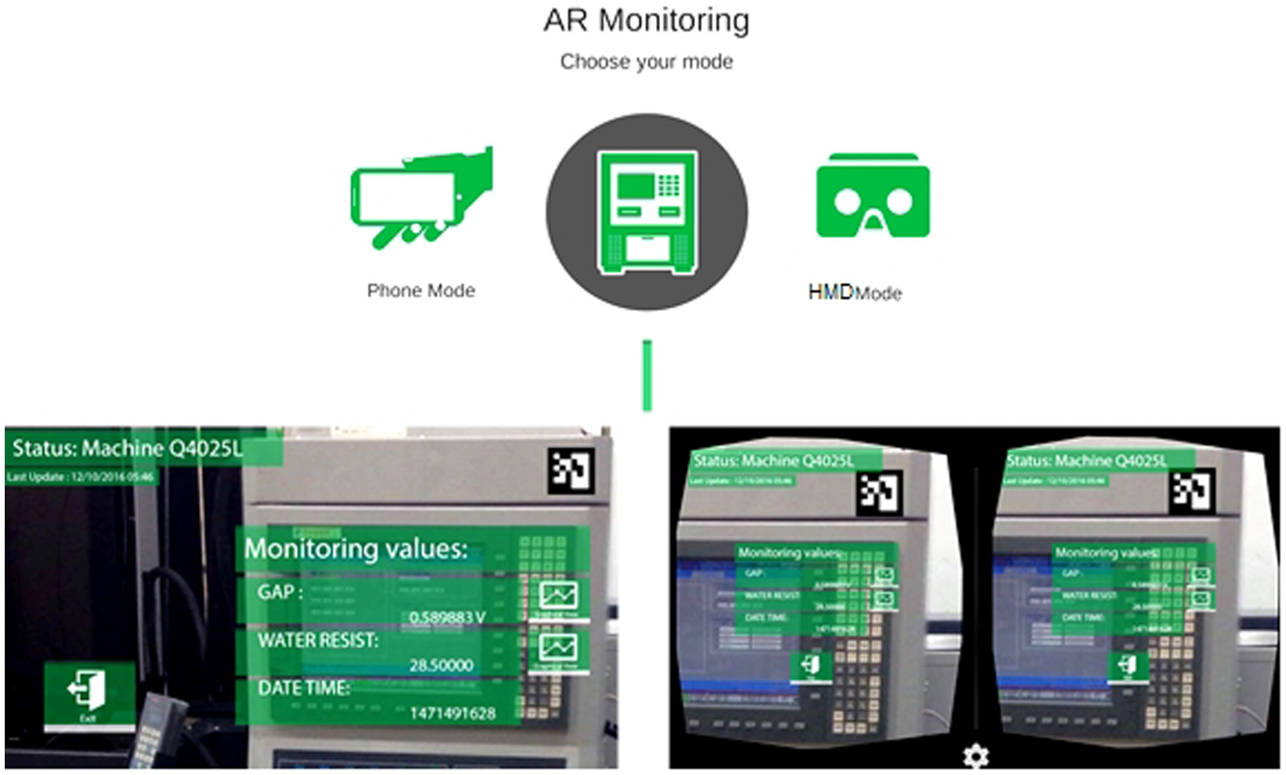
Two modes, the Phone mode and the HMD mode, of the AR UI.
The configuration level is also realized at the cloud side, along with the PAC and the actuators set up at the connection level, to perform supervisory control for making machines self-configured and self-adaptive. An RCS can be set up at the level to apply the controls corresponding to the decisions made at the cognition level to make machines self-adjust for variation and self-optimize for disturbance. For example, we are developing intelligent algorithms to dynamically figure out optimal manufacturing parameters for current machine states. Once the development of such algorithms is finished, the optimal manufacturing parameters can be adjusted and set by the PAC automatically. For another example, air conditioning actuators are used to set the surrounding environment of machines to be of steady temperatures so that the machine performance is more stable.
Now we describe the positioning algorithm using the RFID tags and BLE beacon devices, which is called the RFID/BLE positioning algorithm. The algorithm is the combination of the angle of arrival localization with received signal strength indication difference (ALRD) positioning method 24 using RFID tags and the weighted centroid localization (WCL) method using BLE beacon devices. The RFID tag has a shorter communication range than the BLE beacon device. Hence, RFID tags are for small area positioning, while BLE beacon devices are for large area positioning. We first show how ALRD using RFID tags is implemented. In the implementation, an RFID reader’s position is known in advance and is regarded as an anchor node for the purpose of positioning. Each reader is equipped with two directional antennas, the orientations of which are perpendicular, as shown in Figure 14. The ALRD method first fits the received signal strength indication (RSSI) values of signals sent by a tag and received by an antenna into a parabolic function of the angle of arrival (AoA) between 0° and 90° by applying quadratic regression analysis. Note that the AoA of an incident signal is defined as the angle from the propagation direction of the signal to the orientation of the directional antenna receiving the signal. The AoA is assumed to be positive if it is counterclockwise and negative otherwise. The ALRD method also fits the difference of the signal RSSI values of the two antennas into a linear function of the AoA between 0° and 90° by applying linear regression analysis. The proposed method deploys anchor nodes in a specific manner such that a tag’s signals can be received by two or more beacon nodes, the positions of which are known in advance. Afterwards, by the parabolic function and the linear function, the proposed method can estimate the AoA of a tag with respect to two anchor nodes. As shown in Figure 15, the position (x, y) of a tag can thus be easily calculated according to equation (1)

where D is the distance between the two anchor nodes.
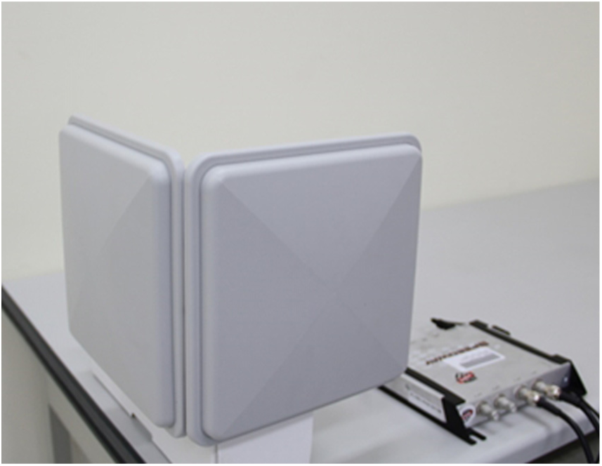
Each ALRD anchor node is equipped with two directional antennas of perpendicular orientation.

Two ALRD beacon nodes can determine the position of a tag.
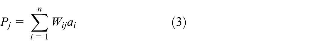
We now describe how the WCL method using BLE beacon devices is implemented. In the implementation, every BT reader’s position is assumed to be known in advance and is regarded as an anchor node for the purpose of positioning. Each reader is equipped with an omnidirectional antenna. For a BLE beacon device to be positioned accurately, the WCL method25,26 requires that three or more readers can receive the device signals. After receiving the signal from a BLE beacon device j, a BLE reader i records the RSSI value as RSSIij and its X and Y coordinates as ai = (xi, yi) to be forwarded to the gateway. After receiving the forwarded messages about the beacon device j from n, n ≥ 3, BT readers within a short period of time, the WCL method calculates the weight Wij for the anchor node i with respect to the device j according to equation (2)

Note that in equation (2), g is the degree determining the contribution of the RSSI values. As suggested by our work in Subakti and Jiang, 26 g is set at 2 after observing extensively the experimental results. Afterwards, the position Pj of the beacon device j can be calculated according to equation (3). The WCL is implemented and 30 arbitrary positions are chosen for evaluating the positioning errors in Subakti and Jiang. 26 Table 3 shows the WCL positioning errors. When g is set at 1, the smallest error is 21 cm, the largest error is 188.5 cm, and the average error is 96.55 cm. When it is set at 2, the smallest error is 12 cm, the largest error is 102.5 cm, and the average error is 46.8 cm. Indeed, setting the g value at 2 leads to lower errors
Position errors for the WCL method.

WCL: weighted centroid localization.
Below, we show how our CPS implementation addresses the 3C facets, namely, coalition, customer, and content. In the coalition facet, we consider how to integrate different parties related to the manufacturing process of a product via the Open Platform Communication Unified Architecture (OPC UA) protocol. The OPC UA protocol is an industrial automation and data communication protocol developed by the OPC Foundation. OPC UA adopts a platform-independent service-oriented architecture that integrates all the functionalities of the individual OPC early specifications, such as Data Access (DA), Alarm and Event (A&E), and Historical Data Access (HAD). Entities in our CPS implementation use the OPC UA functionality for conducting data exchange horizontally with other entities in different external parties and/or vertically with internal management systems such as MES and ERP. For example, with the help of the cloud, an SCM system can be set up, which is defined in Wikipedia 27 as “the management of the flow of goods and services, involving the movement and storage of raw materials, of work-in-process inventory, and of finished goods from point of origin to point of consumption.” With the CPS considering the coalition facet, different parties involved in the SCM can co-schedule their raw material supplies and/or value-added processes in order to provide the right product for customers at the right time, at the right place, with the right quantity, right quality, and right status. If there is any change in the specification, different parties may jointly reschedule the supply chain timely.
The customer facet pays attention to customers who can participate in designing the product, keep track of the manufacture of the product, and even modify the product specifications during the manufacture. Considering the customer facet, the SF-CPS is designed and developed to accept various orders of different demands with small quantities from a variety of customers. After the product is delivered, the customers can continue acquiring services (e.g. the after-sales service and even the recycling service) for utmost quality of user experience. The considerations in the customer facet can respond to the shift from the conventional “mass production” paradigm to the newly emerging “mass customization” paradigm. The former paradigm is for producing a large number of products of the same specification, while the latter is for producing a variety of products of different specifications. To sum up, the customer facet emphasizes customers and advocates the product whole lifecycle service.
When the content facet is considered, the CPS is designed and developed to extract, store, and inquire product traceability. All data about product orders, product descriptions, production environment conditions, production parameters, warehouses, shipment, and after-sales service details are extracted and stored properly for future inquiries. Since the stored data are either structured (such as product material suppliers and production parameters) or unstructured (such as customer service product images and audio clips), Not only Structured Query Language (NoSQL) databases, such as MongoDB, 28 are used to store all the data to realize the big data storing functionality. Traditional relational databases rely on the relational model to store data in tables according to predefined schemas. They are usually called the Structured Query Language (SQL) databases, as they use SQL for database manipulation under strong consistency constraints. Unlike SQL databases, NoSQL databases are schema-less, as they do not need to predefine schemas before storing data. They are thus very flexible for storing various forms of data. NoSQL databases involve sharding and replication. Sharding is to split data into partitions or shards to be stored in distributed server nodes. Replication is to mirror data across distributed server nodes for improving data availability and data processing throughput or speed. By adding more distributed server nodes, the data volume is increased, while data availability and throughput are maintained. NoSQL databases thus have the advantages of large data volume and horizontal scaling. They are also fast because they obey weak consistency constraint instead of strong consistency constraint to trade consistency for processing speed. The data stored in the database are useful not only for the product whole lifecycle service, but also for modern data analysis schemes, like the big data analysis, 29 machine learning, 30 and deep learning 31 schemes, to perform prognostics and health management (PHM) 32 of machines, to optimize the production process, 30 to predict future demands, to improve services, and/or to save energy in production. 33
Since the cloud plays an important role in our CPS implementation, we now describe cloud implementation considerations. There are mainly two types of clouds: the public cloud and the private cloud. A cloud is called a “public cloud” if the cloud service is open for public use. Typical public cloud examples are Amazon Elastic Compute Cloud (EC2), Microsoft Azure, Google AppEngine, IBM Blue Cloud, Oracle Cloud, and so on. A cloud is called a “private cloud” if it is operated only for a single organization. It may be hosted inside or outside the organization and managed internally or by a third party. In order to have overall control in all aspects of setting up the cloud environment, we select the “private cloud” type. OpenStack, a free and open-source software for cloud computing, is utilized to set up a private cloud to realize the elastic computing functionality. The “Infrastructure as a Service (IaaS)” and “Platform as a Service (PaaS)” modes are adopted to deploy and launch three virtual machines (VMs) atop the private cloud, one for running the SF-CPS data center main program, another for running a NoSQL MongoDB database, and the other for running the programs related to the levels/facets of conversion, cyber, cognition, configuration, coalition, customer, and content. Information about the VMs is as follows: the first has four virtual CPUs (VCPUs), 8 GB memory, and 100 GB disk space; the second has two VCPUs, 16 GB memory, and 1024 GB disk space; the third has two VCPUs, 8 GB memory, and 100 GB disk space. Since the cloud features flexibility, elasticity, and scalability, we can dynamically start or stop VMs to respond to practical resource requirements.
Conclusion
In this article, we have proposed an 8C architecture to build the CPS for smart factories. The architecture is based on the existing 5C architecture 9 consisting of five levels, namely, the connection, conversion, cyber, cognition, and configuration levels. In addition to the five levels, the 8C architecture adds three facets, which are coalition, customer, and content. Unlike the existing 5C architecture that concentrates more on vertical integration, the proposed 8C architecture concentrates more on vertical integration and cross-level relationship by adding the three facets. To be more precise, the 3C facets concentrate on the horizontal integration of the CPS, such as the integration (or coalition) of different parties and their associated information (or content). They also emphasize the most important party (i.e. the customer) on the basis of the product-centric manufacturing concept. By the concept, the factory can respond fast to various product orders by automatically preparing materials, flexibly scheduling production processes, dynamically reconfiguring production lines, and automatically arranging storage and delivery for the product. In this way, both mass customization and mass production can be realized.
We have also shown the design and development of a CPS on the basis of the 8C architecture for the WEDM smart factory produced by CHMER. 14 Abiding by the concept of product-centric manufacturing, the CPS keeps track of the product. Therefore, an IIoT gateway is designed and an RFID tag and a BLE beacon device are attached to a fixture or a jig. The RFID tag and the BLE beacon device periodically send wireless signals to be received by the IIoT gateway and to be forwarded to the cloud-side data center server for the purpose of tracking the product workpiece fixed on the fixture. An indoor localization method WCL is implemented for localizing the product accurately, which benefits product movement, storage, and shipment. Many protocols, such as the MQTT and the OPC UA, and systems, such as the MES, PIMS, WMS, CMMS, SCM, ERP, and AR, have been integrated or will be integrated into the CPS. We are now planning to add the 9th C, the confidentiality, into the CPS architecture to build the CPS for smart factories, so that the CPS is confidential, secure, robust, and resilient to attacks.
Footnotes
Handling Editor: Stephen D Prior
Declaration of conflicting interests
The author(s) declared no potential conflicts of interest with respect to the research, authorship, and/or publication of this article.
Funding
The author(s) disclosed receipt of the following financial support for the research, authorship, and/or publication of this article: This work was supported in part by the Ministry of Science and Technology (MOST), Taiwan, under grant nos 105-2218-E-008-012-, 105-2221-E-008-078-, and 106-2218-E-008-006-.