
Abstract
We propose to apply Udwadia–Kalaba theory to the bulldozer dynamics analysis. The bulldozer system is divided into several subsystems by this approach, which simplifies the modeling process for multi-link mechanism. Based on this approach, the constraints are classified into structure constraints and performance constraints. Structure constraints are used to set up dynamic model without regard for trajectory. Performance constraints are the desired trajectory. Then, according to the equation of motion of the unconstrained system established by Lagrange approach and system constraints which include structure and performance constraints, an explicit, closed-form analytical expression for the control force can be obtained by solving Udwadia–Kalaba equation. We demonstrate that this approach does not need to solve Lagrange multiplier, which is always difficult to obtain. However, for bulldozer link lever system, the initial conditions are difficult to satisfy the constraints in the actual situation. Thus, the problem of initial condition deviation is taken into consideration. In the end, the numerical simulations are done to prove that the trajectory of the bulldozer satisfies the designed one and the real-time forces are conveniently acquired.
Keywords
Introduction
Bulldozer and other engineering machinery play an important role in many fields, such as industrial production and rescue emergency. Therefore, researchers have paid more and more attention to it.1–6 As for the bulldozer, its link mechanism is designed for a variety of styles in order to satisfy different work conditions, such as road construction and minerals exploitation. The research about dynamic modeling and control design7–11 of the link mechanism is important. Usually, the most common link mechanism of the bulldozer is 2-degree-of-freedom hybrid mechanism. The two degrees of freedom correspond to the rotation and movement of the bucket, respectively. The object of study is a typical closed-loop hybrid mechanism.
Generally, when there is a coupling relationship between the coordinates in a system, it is difficult to establish the overall kinetic and potential energy. As a result, obtaining its dynamic equation is also difficult by Lagrange method. Moreover, Lagrange equation 12 applies to holonomic systems subject to ideal constraints. But it is not easy to analyze a complex multi-degree-freedom system which is subject to many kinds of constraints such as nonideal constraints. 13 Several mathematicians and physicists have done esteemed contributions in analytical dynamics. Gauss introduced Gauss principle14–16 for handing constrained motion. Gibbs and Appell offered GA equation17,18 for constrained motion by virtue of the concept of quasi-coordinates. Dirac developed an algorithm 19 for determining Lagrange multiplier. These methods are all based on the D’Alembert principle that is the virtual displacement principle. That is to say, they are all equivalent. In other words, it is difficult to obtain the explicit equations of motion by these methods, especially for the mechanical system with hybrid mechanism or large number of degrees of freedom. In 1992, Udwadia and Kalaba obtained a novel, concise, and explicit equation of motion for constrained mechanical system that may not satisfy the D’Alembert principle. Furthermore, this approach can deal with different kinds of constraints including holonomic and nonholonomic ones as well as ideal and nonideal ones. Until now, some researchers have analyzed single rigid body,20,21 series combined mechanism, 22 parallel mechanism, 23 and flexible continuous structural systems24–26 by Udwadia and Kalaba approach and designed effective controllers to deal with the problem of trajectory tracking control. In this article, we propose to apply this theory to hybrid mechanism.
According to Udwadia and Kalaba theory,27–32 we first establish the dynamic model of the link mechanism by four angle coordinates, which not only makes the modeling process simple and effective but also reduces the dimension of the dynamic equation. In addition, there is no need to solve the complicated Lagrange multipliers during the modeling process. Second, the constraints are classified as structure constraints and performance constraints. The structure constraints are used to describe the relative positions and motion relations of each subsystem. The performance constraints are the desired trajectory of link mechanism. Finally, according to the equation of motion of the unconstrained system established by Lagrange approach and system constraints, an explicit, closed-form analytical expression for the control force can be obtained by solving Udwadia–Kalaba equation. In this way, we can obtain the real-time output torques of the bulldozer linkage system to meet the desired trajectory. Furthermore, the initial condition deviation is considered. The object can meet the desired trajectory when the initial conditions do not satisfy the constraints. In the end, this approach is verified in MATLAB simulation by ode45 integrator. Numerical simulation shows that using the Udwadia–Kalaba control scheme, and the final error between the actual angle and the desired angle is in the order of
Details of Udwadia–Kalaba theory
In this section, the fundamental equation called Udwadia–Kalaba equation for constrained mechanical system will be given.27,28 There are three steps to complete the process of dynamic modeling and trajectory tracking using this equation. 30
First, we convert the original system to be discrete as “unconstrained” dynamical system which can be described by

where

Second, we will consider the actual constraints imposed on the system. Specially, there is no limit to the kinds of constraints which can be holonomic, nonholonomic, scleronomic, or rheonomic. Now, we shall assume the system is subjected to


Next, we need to transform the constraints equation into matrix form by differentiating holonomic constraints and nonholonomic constraints with respect to time twice and once under the assumption that equations (3) and (4) are sufficiently smooth. 34 The matrix form is given as follows

where
Remark 1
The constraints used in Lagrange equation, 12 Maggi equation, and Gibbs and Appell17,18 equation are either zeroth-order form or first-order form. Compared with these, the equation used in this article is in the second-order form, which is regarded as the most suitable form for further dynamic analysis because of the acceleration linearity. 34 Besides, we don’t need to consider the problem of constraints information loss (i.e. a constant) due to the differentiation. The reason is that the information is still retained in the initial conditions as shown in equation (1).
The last step is to impose the additional generalized forces of constraints on the system. Thus, equation (1) will be changed to obtain the actual explicit equations of motion in the form of

where
Udwadia and Kalaba proposed that the constraint force is explicitly given by

where
Thus, the explicit equation of motion for constrained system can be obtained from equations (6) and (7) as follows

Trajectory tracking control of the bulldozer
Dynamic model of the bulldozer
Bulldozer link lever system is composed of four rods including the boom, rocker arm, connecting rod, and bucket. In this system, there are two input forces and two degrees of freedom, which are rotations of boom and rocker arm. In this section, we shall focus on the dynamic model of the four rods. From Figure 1, the bottom of bucket is hinge connected to the boom of which another end is hinge connected to the frame, and the upper of bucket is hinge connected to the connecting rod of which another end is hinge connected to rocker arm. The two input forces drive the boom and rocker arm to control the movement of the bucket.

The bulldozer system.
Next, we select the coordinate system OXY to establish the dynamic model of the link lever system as shown in Figure 2. The origin of the coordinate system O is connecting point between frame and boom.

Model of link lever system.
Remark 2
In Figure 2,
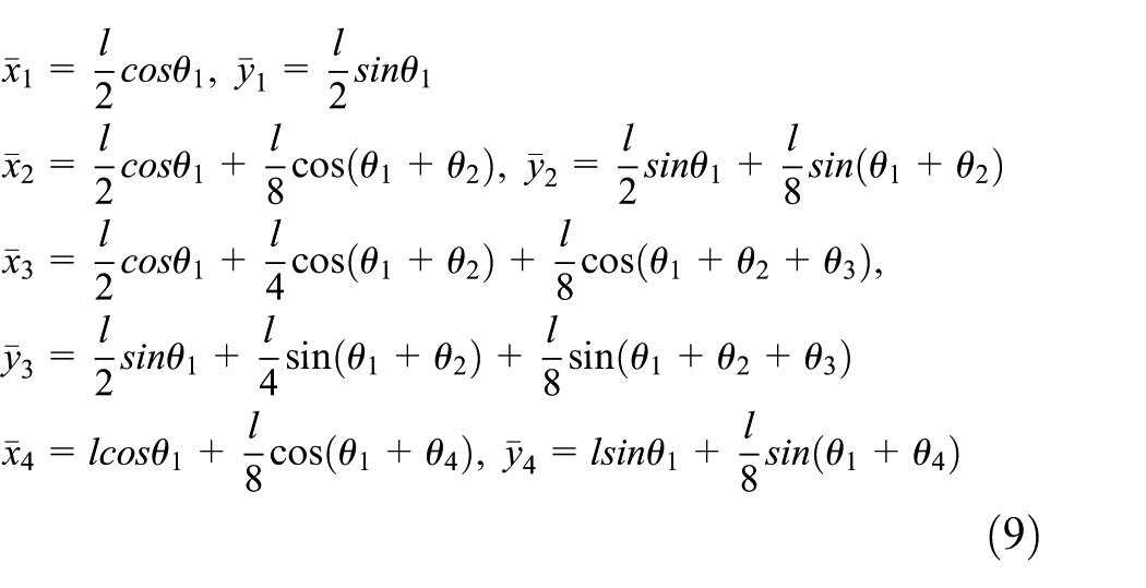
Then, by differentiating equation (9) with respect to time, the centroids’ velocities can be obtained

The kinetic and potential energy of each rod can be written as
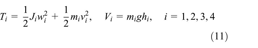
where
Thus, the dynamic equation of the “unconstrained” system based on Lagrange equation can be represented as

where
Structure constraint of the bulldozer
In this section, the structure constraints will be given and converted into the second-order form. Since the bucket is connected to both boom and connecting rod, we have two ways to express the position of point 4, which are from O to points 2,3,4 and from O to points 1,4
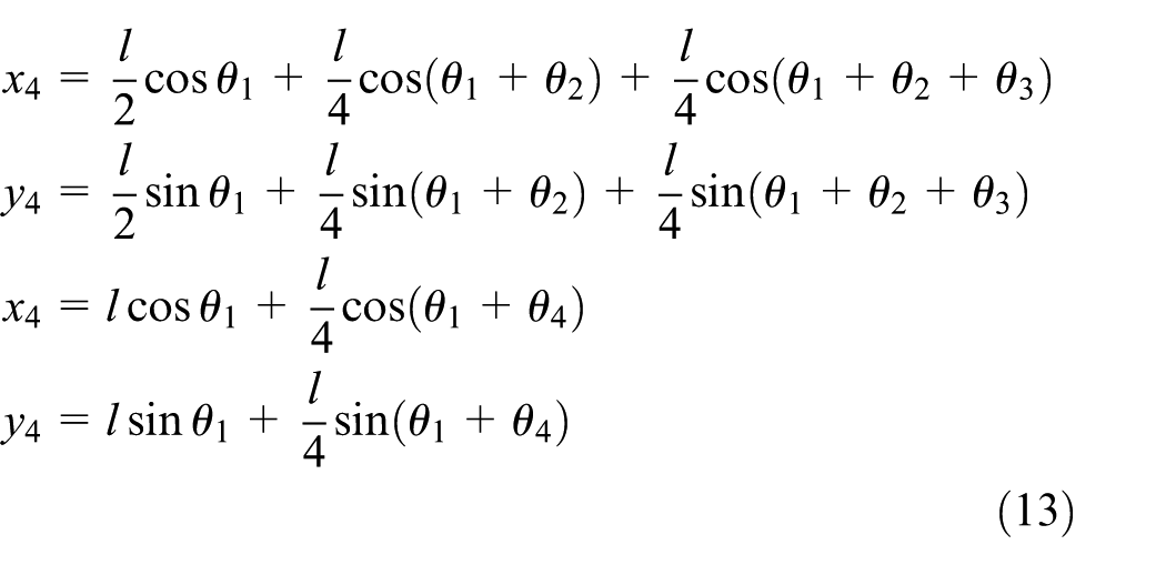
Therefore, we could get

Differentiating equation (14) with respect to time twice, we can get the second-order form of structure constraints (equation (28)), which is given in Appendix 1.
Trajectory tracking simulation of the bulldozer
In this section, we will combine the second-order-form structure and performance constraints into the matrix form. Then, an explicit, closed-form expression for the required control force will be obtained based on Udwadia–Kalaba approach, which makes the rods precisely meet the trajectory requirements.
Performance constraint of the bulldozer
Case 1: filling movement of bulldozer bucket
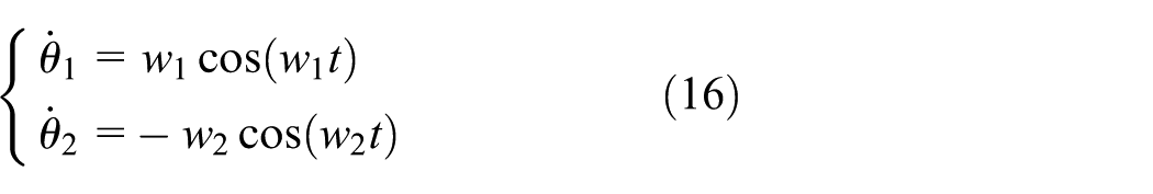
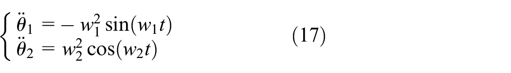
First, we assume that the pre-specified trajectory of the system is represented by the following equation (15). This equation indicates the filling movement of bulldozer bucket

Differentiating the constraint equation (15) with respect to time once and twice, we can get
Case 2: ascending movement of bulldozer boom
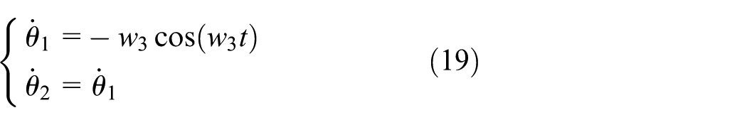
Next, we give another pre-specified trajectory of the system as equation (18) shows. This equation indicates the ascending movement of bulldozer boom

Differentiating the constraint equation (18) with respect to time once and twice, we can get

Remark 3
Before separating the system into four subsystems, the original system only has two degrees of freedom. Hence, we need two structure constraints to revert it to the actual situation and two performance constraints to limit the original degree of freedom. For an actuation system, the number of performance constraints equals to the number of inputs. The number of structure constraints equals to the number of extra coordinates due to the process of system separating.
Remark 4
In Udwadia–Kalaba approach, equations (15) and (18) are called performance constraint, which means the rods’ trajectory must satisfy the pre-specified trajectory under the action of real-time input forces.
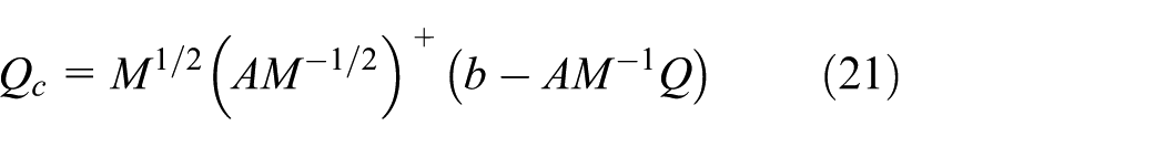
According to the Udwadia–Kalaba approach, the closed-form control force can be expressed as
Remark 5
Based on this dynamic model,

Case 3: initial condition deviation
In reality, it may be difficult to obtain the initial conditions such as initial positions and velocities. Therefore,

with

where
Remark 6

Differentiating the constraint equation (25) with respect to time once and twice, we can get


Combining equations (28) and (17), we can obtain the second-order form constraint,
Simulation results
In this part, we conduct the simulation analysis of the bulldozer link lever system based on equation of motion developed in the previous section. The values of the parameters defined in Table 1 are given as follows.
Parameters for simulation.

In this article, the simulation process is done by ode45 integrator in MATLAB, and the simulation time is 60 s.
Case 1: the simulation for filling movement of bulldozer bucket
By letting
Initial conditions in case 1.

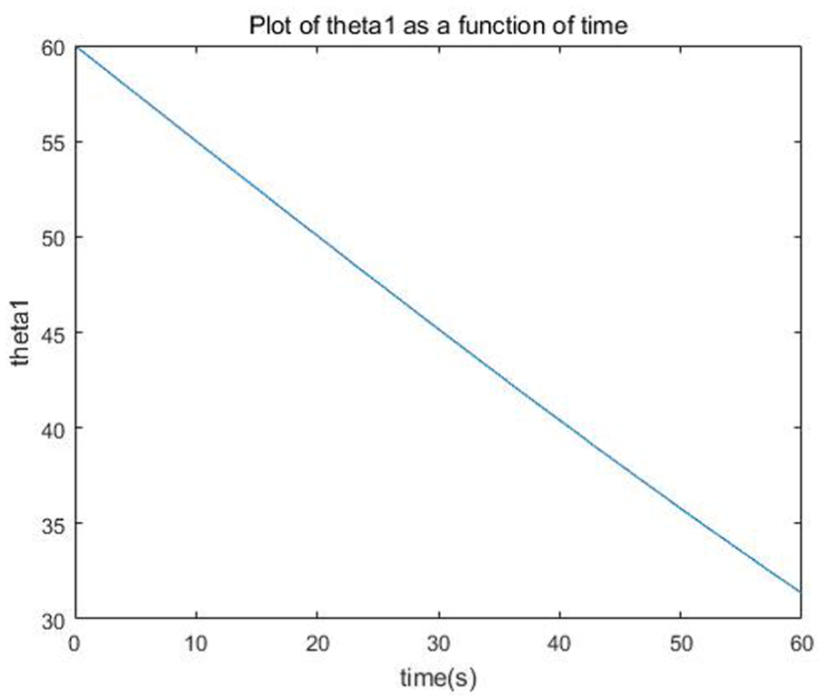
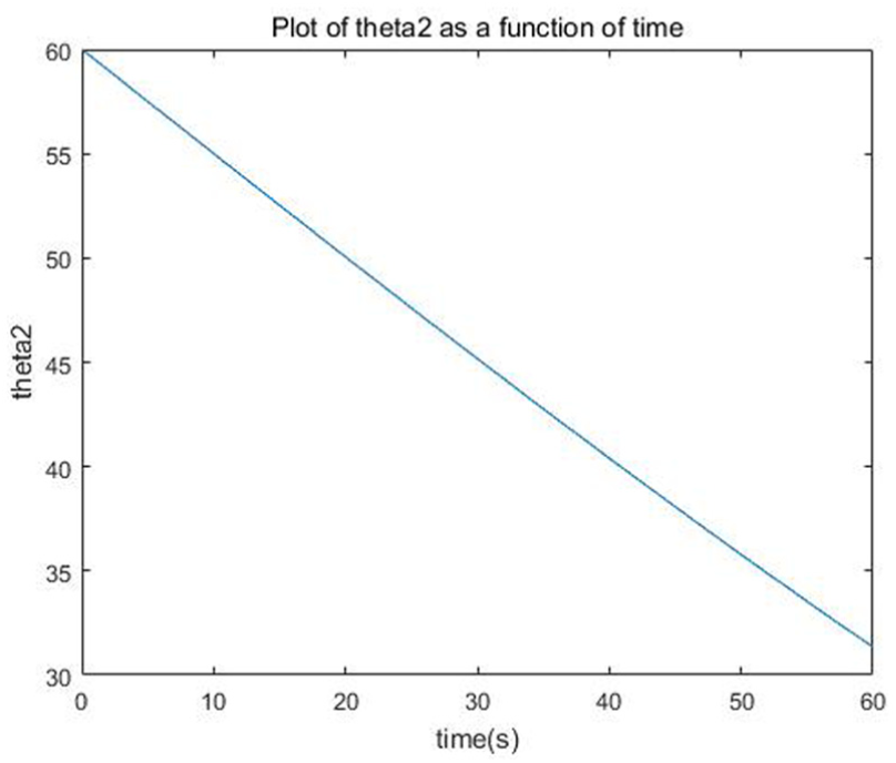
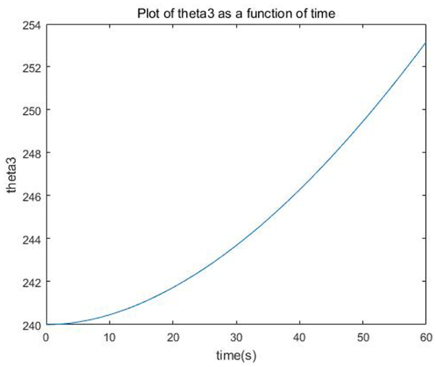
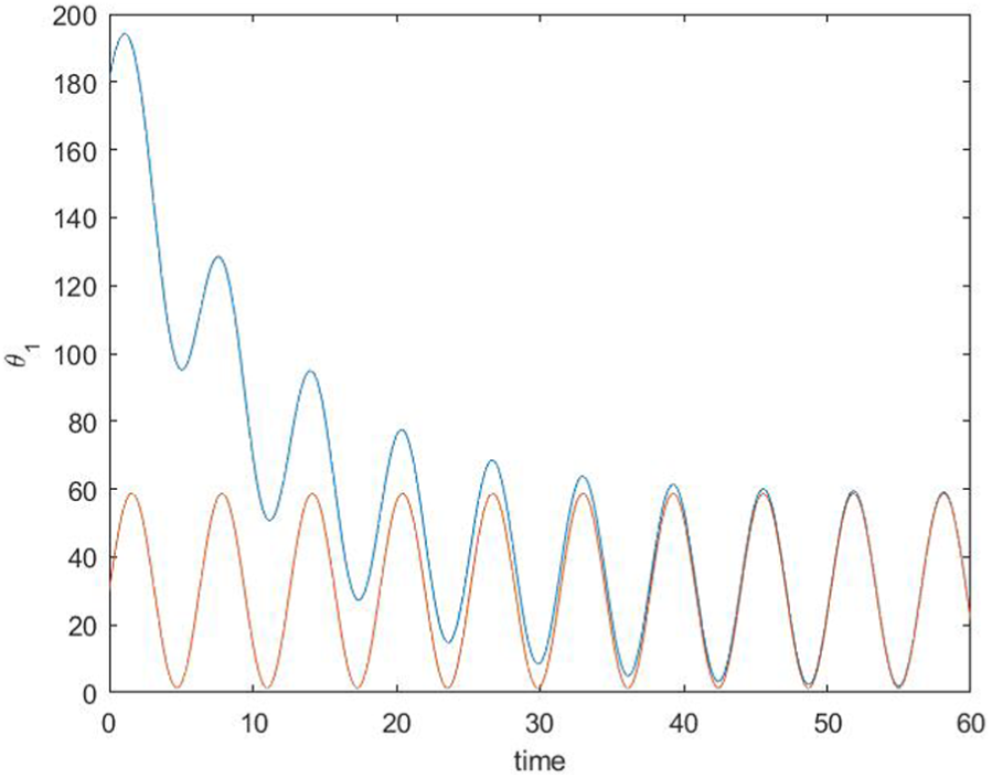
From Figures 3–6, the calculated trajectory of the four angles as functions of time is given. Figures 3 and 4 show that the calculated trajectory of angles

The variation of parameter
The variation of parameter
The variation of parameter

The variation of parameter
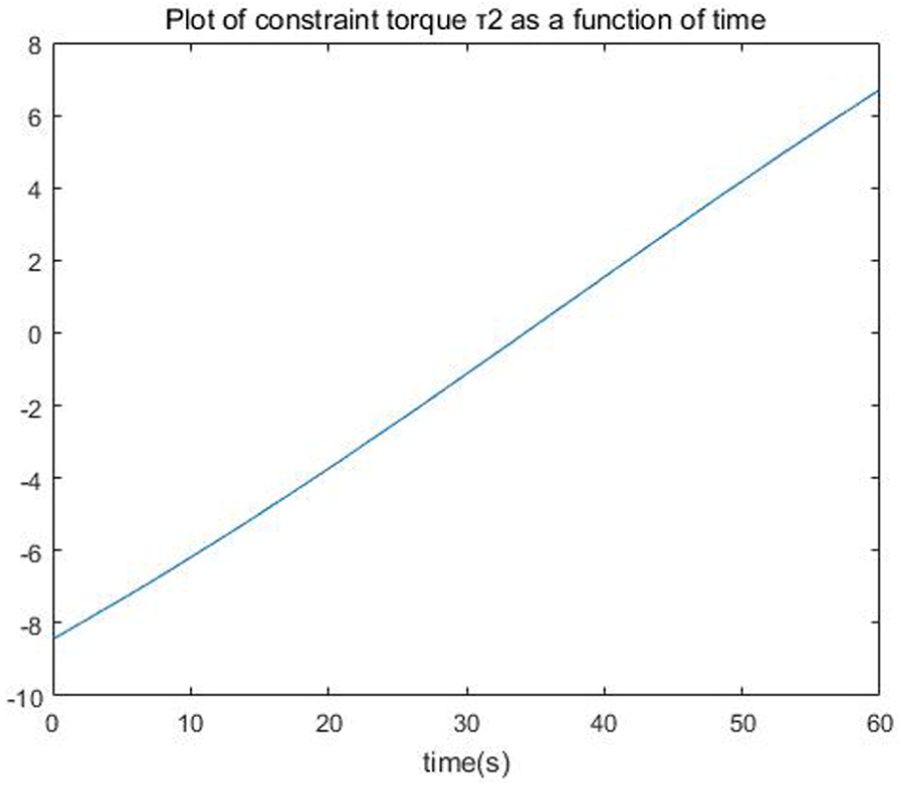
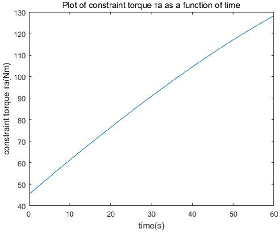
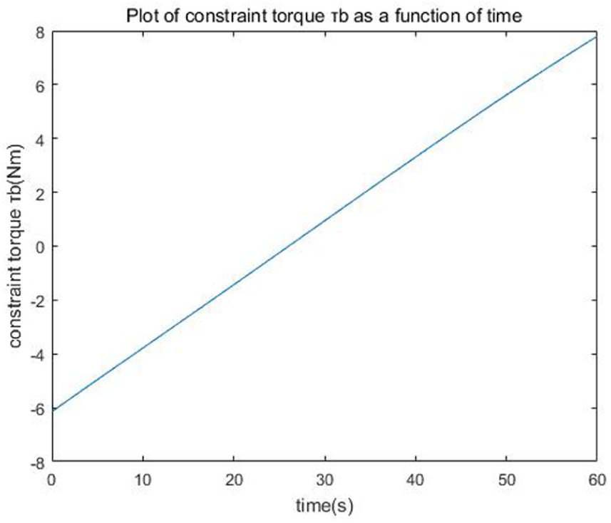
Figures 7–10 show the four elements (i.e. the torque acting on the four joints) of control force
Torque between boom and frame in case 1.

Torque between boom and rocker arm in case 1.

Torque between connecting rod and rocker arm in case 1.
Torque between bucket and boom in case 1.
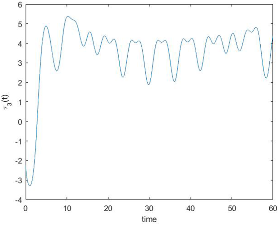
As mentioned above, there is only two actual input torques which are given in equation (22). In Figures 11 and 12, we show the variation of two elements of

The actual input torque 1 in case 1.

The actual input torque 2 in case 1.
Besides, the tracking errors of

The error of

The error of
In this article, we define
Case 2: the simulation for ascending movement of bulldozer boom
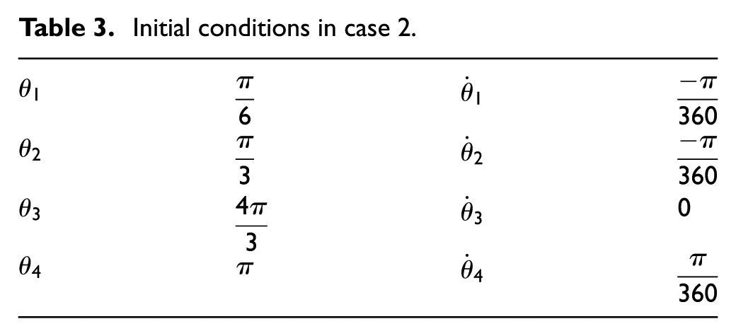
Similarly, let
Initial conditions in case 2.
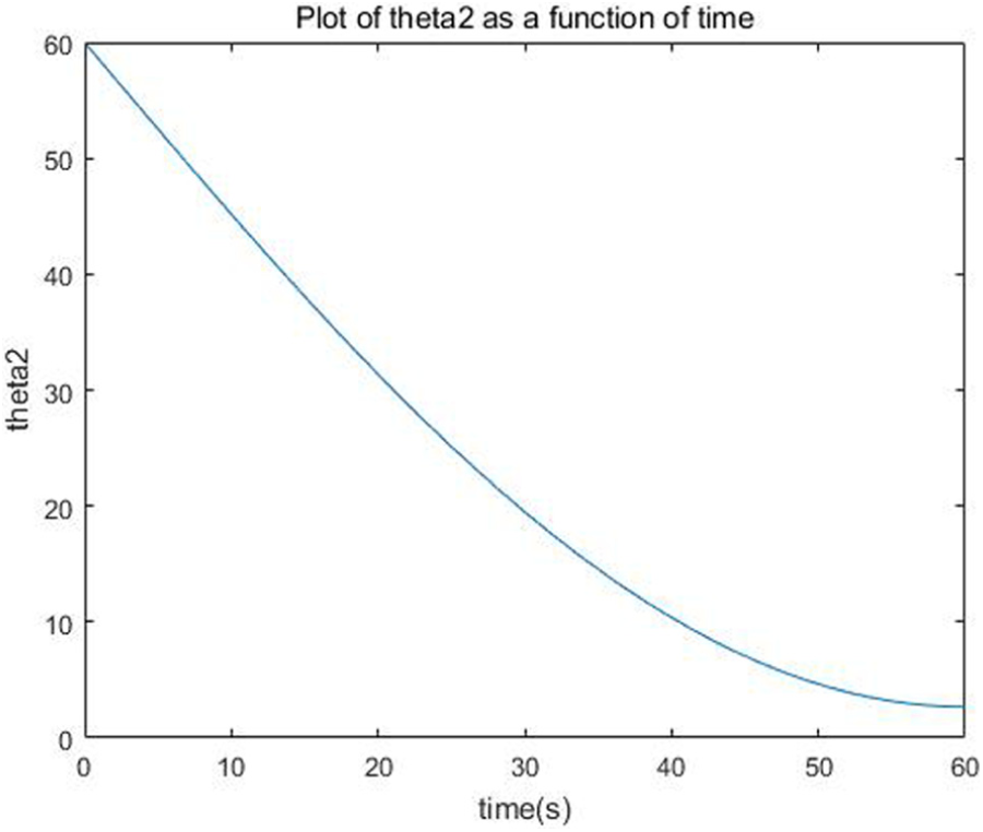
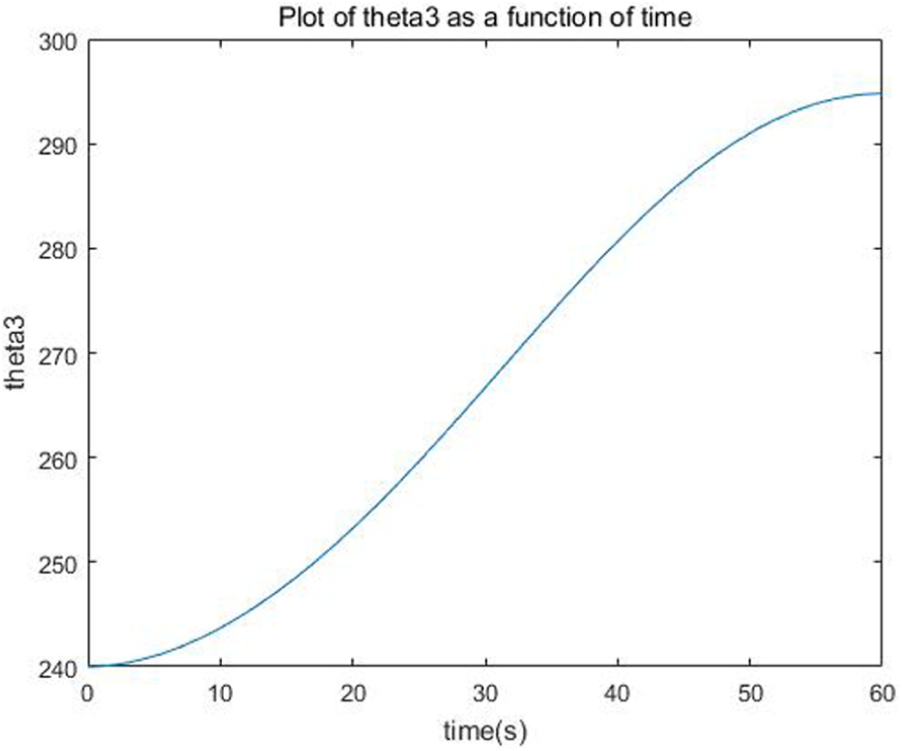
From Figures 15–18, we can see the variation of the four angles as functions of time. Figures 15 and 16 show that the angle
The variation of parameter
The variation of parameter
The variation of parameter

The variation of parameter
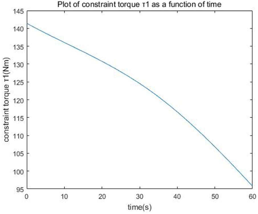
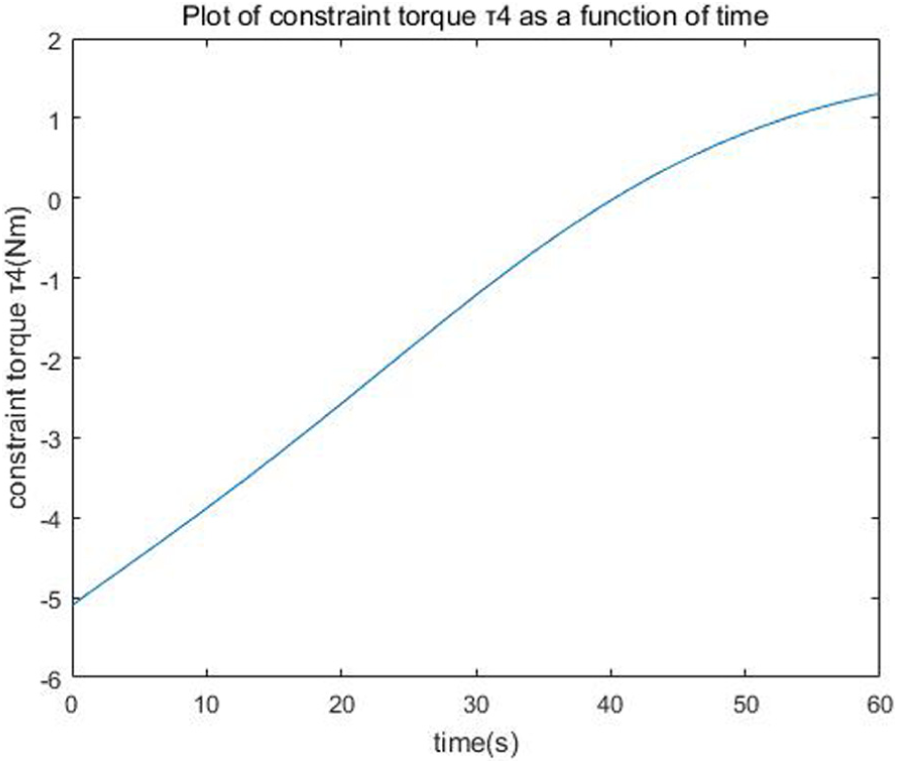
Figures 19–22 show the four elements (i.e. the torque acting on the four joints) of control force

Torque between boom and frame in case 2.
Torque between boom and rocker arm in case 2.

Torque between connecting rod and rocker arm in case 2.

Torque between bucket and boom in case 2.
Figures 23 and 24 show the variation of two elements of
The actual input torque 1 in case 2.
The actual input torque 2 in case 2.
The tracking errors of

The error of

The error of
Case 3: initial condition deviation
We can obtain the initial conditions as shown in Table 4.
Initial conditions in case 3.

We make the initial position of
The variation of

The variation of parameter
Figures 29–32 show the four elements (i.e. the torque acting on the four joints) of control force

Torque between boom and frame.

Torque between boom and rocker arm.
Torque between connecting rod and rocker arm.

Torque between bucket and boom.
Conclusion
In this article, we propose to apply Udwadia–Kalaba approach to trajectory tracking control of the bulldozer link lever system. First, we establish the nonlinear dynamic model of the system and analyze the “unconstrained” rods. Next, the system structure and desired trajectory are regarded as the structure constraints and performance constraints, respectively. Finally, this approach provides an explicit, closed-form analytical expression for the control force by solving Udwadia–Kalaba equation. The simulation results show that the servo constraint torques based on Udwadia–Kalaba equation make the rods’ movement meet the designed trajectory precisely. In summary, there are three main advantages of this approach in this article. First, this article provides an easy dynamic modeling process for bulldozer link lever system. The constraints in the system which can be holonomic as well as nonholonomic are divided into structure constraints and performance constraints. We only need to get the second-order-form constraints. It is more convenient compared with the common approach. Second, the control performance is excellent due to the exact equation of motion by this approach. However, in other approaches, there are approximations of equation of motion or modification of the controller such as Lagrange multiplier which make the equation complicated and the tracking performance not optimistic. Third, the initial condition deviation is considered. Using the modified control, the object in this study can meet the desired trajectory when the initial conditions do not satisfy the constraints. On the whole, it is convenient to establish the dynamic model and obtain the servo constraint torques of bulldozer link lever system by Udwadia–Kalaba approach.
Footnotes
Appendix 1
The matrices
and equation (28) is given as follows
The matrices
where
where
and
Acknowledgements
Author thanks and sincerely appreciates to mother Huifang Dong and wife Qiaozhi Zhang for their love, patience and support during the process of research.
Handling Editor: Chuanzeng Zhang
Declaration of conflicting interests
The author(s) declared no potential conflicts of interest with respect to the research, authorship, and/or publication of this article.
Funding
The author(s) disclosed receipt of the following financial support for the research, authorship, and/or publication of this article: This research was supported by National Natural Science Foundation of China (no. 51505116) and China Post doctoral Science Foundation (2016M590563).