
Abstract
The unstable cavitation flow and the dynamic characteristics of oil-gas multiphase pumps usually lead to vibration, noise, and even pump damage. The multiphase flow mixture model and the full cavitation model were used to simulate the transient flow and dynamic features of the pump. The results show that cavitation changes the inflow conditions, aggregates the unstable flow, and generates large pressure pulsations. It also accelerates the variation frequency of axial force and intensifies the uneven distributions of internal flow and circumferential pressure. Both the radial force on the impeller and its variation amplitude are enlarged. Understanding the characteristics of unsteady excitation induced by cavitation can provide references for studying the mechanism of vibration and noise in multiphase pumps.
Keywords
Introduction
Multiphase pumps are mainly used in oil fields to boost the pressure of oil and gas phases. The large variation of gas contents will lead to drastic pressure fluctuation at the pump inlet, and the flow will become more complicated if cavitation occurs. Cavitation will interfere and prevent the energy exchange among fluids and give rise to a series of problems, such as variation of operating characteristics, vibration, and noise.1–3 The periodic formation and collapse of cavitation bubbles will make the cavitation flow even more unstable resulting in the internal flow field pulsations. The peripheral pressure pulsations could even increase the torque on pump shaft and lead to shaft fracturing. 4
Numerical modeling becomes one of the important means to study the cavitation flow. It can make up for the deficiency of experimental studies and can also obtain relatively accurate calculation results.5–7 The reliability of numerical calculation for cavitation flow in pumps has been improved by the continuous modification of cavitation models with the help of experimental methods.8–12 It is now possible to numerically study the transient dynamic characteristics of pumps, and there are many related research results. Using a two-dimensional unsteady Navier–Stokes analysis with the simplest treatment of bubble dynamics, Saito et al. 13 simulated the cavitation flows around an axial-flow pump blade to capture the transient stages with high amplitude pressure changes during the birth and collapse of bubbles. Zhang et al. 14 simulated the three-dimensional unsteady turbulent flow in axial-flow pumps using the Navier–Stokes solver embedded with k–ε RNG turbulence model and the SIMPLEC algorithm and discussed the pressure fluctuation, static pressure distribution, and axial velocity at the rotor outlet; few years later, Zhang et al. 15 analyzed the transient characteristics of tip leakage vortices and the tip leakage dynamics in axial-flow pumps using LES to predict and control cavitation, noise, and vibration. Feng et al. 16 found that the cavitation performance of axial-flow pumps can be improved at the off-design flow conditions by adjusting the inlet angles of guide vanes, the variation trend of vapor fractions can be used to predict the NPSHR, and the merging of cavitation zones between the tip and the hub at the blade suction side indicates the deterioration of pump performance. Li et al. 17 used the standard k–ε turbulence model, the SIMPLE algorithm, and the sliding mesh technique to simulate the effect of reducing the guide vane thickness in improving the stability of mixed-flow pumps and verified that the thinning of guide vanes can reduce the pressure pulsation amplitudes. Sang et al. 18 analyzed the amplitude, frequency, and variation trend of radial forces within a two-stage axial-flow blood pump using the LES model and PISO algorithm. The development of cavitation flow in the pump will induce the variation of pressure fields, create excitation, and ultimately change the characteristics of transient radial forces on the impeller.
At present, the study of cavitation flow in pumps is mainly focused on the single-phase fluid. In this article, the time domain and the frequency domain of pressure pulsations, as well as the amplitude characteristics of an axial-flow type multiphase pump, were obtained on the basis of numerical modeling of the cavitation flow. The radial force and the axial force on the pump were derived by applying integral to the pressure on the surface of the computational domain, and then the dynamic characteristics of the pump were analyzed. The analyses of mechanical characteristics of the impeller in cavitation flow conditions provide a new reference for studying the mechanism of vibration and noise induced by cavitation flow.
Numerical model
The multiphase flow mixture model and the full cavitation model 19 were used to calculate the cavitation flow in a multiphase pump. The closed turbulent control equations of the standard k–ε model were adopted. The near wall turbulent flow was processed by the standard wall function method. The working fluid was a mixture of petroleum, water vapor, and natural gas. There was almost no water in the fluid, and the viscosity coefficient was measured at different volume fractions. The governing equations and the full cavitation model are as follows.
Control equations
Continuity equation of the mixture

Momentum equation of the mixture
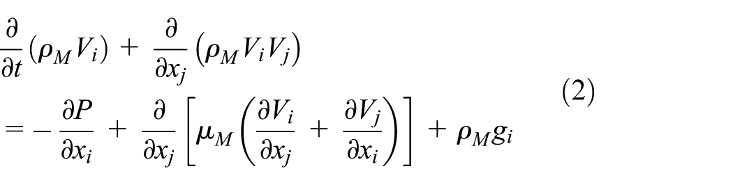
where ρM is the density of the mixture, ρM = ϕlρl+ϕvρv+ϕgρg; ϕl, ϕv, and ϕg are volume fractions of petroleum, water vapor, and natural gas, respectively, ϕl+ϕv+ϕg = 1; ρl, ρv, and ρg are densities of petroleum, water vapor, and natural gas, respectively; t is the time; V is the velocity magnitude of the mixture; μM is the dynamic viscosity of the mixture; g is the acceleration of gravity, while subscripts i and j are tensor coordinates.
Turbulence equations
Turbulence kinetic energy k equation

Dissipation rate of the turbulence kinetic energy ε equation

where k is the turbulence kinetic energy; μt is the eddy viscosity or turbulent viscosity, μt = ρMCμk2/ε, Cμ = 0.09; Gk represents the turbulence kinetic energy generated by the average velocity gradient and Gb represents the turbulence kinetic energy generated by the buoyancy force; C1ε, C2ε, and C3ε are k–ε turbulence model constants, C1ε = 1.44, C2ε = 1.92, and C3ε = tanh(Vx/Vz); ε is the turbulence eddy dissipation; σk and σε are turbulent Prandtl numbers, σk = 1.0, σε = 0.02; and YM represents the contribution of transitional diffusion to the turbulence eddy dissipation during compressible turbulent flow.
Transport equations
Transport equation of the water vapor phase obtained from the continuity equation

Transport equation of the natural gas phase
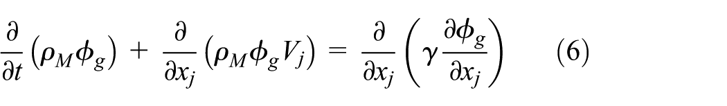
where γ is the effective exchange coefficient.
Cavitation model
Singhal et al. 19 introduced a comprehensive cavitation model (the so-called full cavitation model) based on the simplified Rayleigh–Plesset equation. It was derived for the mixture of a liquid, its vapor, and a small amount of noncondensable gas. Due to the similar nature of petroleum and water, this cavitation model has been used in this work without any modifications.
If P ≤ Pv, bubble growing (cavitation) process

If P > Pv, bubble condensation (collapse) process

where ℜ e and ℜ c are generation rate and condensation rate of water vapor, respectively; σ is the coefficient of surface tension; P is the pressure of the flow field; Pv is the saturation pressure of water vapor; Ce and Cc are constants, Ce = 0.02, Cc = 0.01; subscripts i and j are tensor coordinates; x, y, and z are Cartesian coordinates.
Calculation model of axial force and radial force
The axial force Fz and radial force Fr are calculated by applying integral to the grid area on the surface of the computational domain
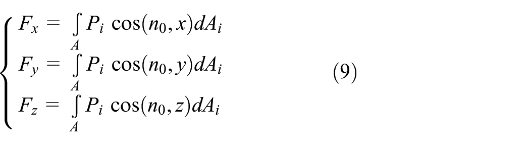

where Fx and Fy are radial force components; Pi is the pressure on the grid cell; Ai is the area of grid cell; and n0 is the normal direction of the grid cell surface.
Geometric model and computational grid division
Design parameters of the pump
The pump used in this research is a three-stage axial-flow type multiphase pump, which is composed by the suction chamber A0, the three-stage compression units A1–A5 (each compression unit is composed by a impeller and its corresponding guide vanes), and the delivery chamber A6, as shown in Figure 1. The design parameters of the pump are as follows: flow rate Qd = 110 m3/h, head H = 90 m, speed n = 2950 r/min, efficiency η = 45%, scope of gas volume fractions ϕg = 0–0.73, number of impeller blades = 4, and number of guide vanes = 9.
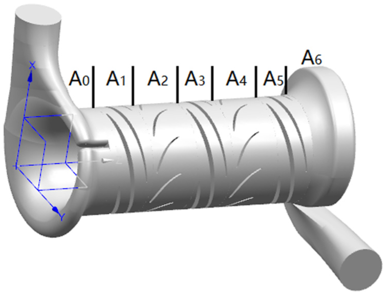
Computational domain of the three-stage axial-flow type multiphase pump.
Division of computational grids
The flow in the compression units was the focus of this study. Therefore, the structured grid was used for the impellers and guide vanes, the O-type grid was used to densify the blade surfaces, and the unstructured grid was used for the suction chamber and delivery chamber, while the sliding grid technique was used to solve the multistage coupling problem between the rotating impeller and its adjacent stationary guide vanes. According to the changing pattern of the pump’s energy performance with the number of grids, the grid independence was verified when the variation rate of efficiency is less than 0.5%, as listed in Table 1. The value of y+ (a dimensionless coefficient reflecting the grid scale on the wall boundary layer) on the blade surface of the computational grid was 50. The numbers of grids determined in this calculation were 855,534 for the suction chamber, 692,624 for the delivery chamber, 528,219 for the impeller, and 461,768 for the guide vanes.
Influence of grid number on pump performance.

Computational boundary conditions
For the inlet boundary conditions, the velocity and the gas volume fractions are given, and it is assumed that the oil and gas phases are evenly distributed. For the outlet boundary conditions, the average sectional pressure is given, and the walls can meet the no-slip conditions. To accurately calculate the transient flow process in the multiphase pump, the steady-state results were used as the initial values, and the time step was taken as 0.113 μs, and the total time of unsteady calculation was 0.186 s.
The convergence residuals of parameters k and ε were calculated, and after 200 times of iteration, they began to converge and the residual curves became relatively flat. After 2500 times of iteration, the calculated results have converged. The convergence residuals of the simulation are shown in Figure 2.

Convergence residual curves of the simulation.
Experimental study
Test bench
The test bench of the multiphase pump is shown in Figure 3. This is an open test bench composed mainly by the multiphase pump, the motor, the torque meter, the water supply pump, the compressor, the mixing tank, the gas flow meter (precision level of 0.02), the liquid flow meter (precision level of 0.05), and the differential pressure transducer (precision level of 2.5).
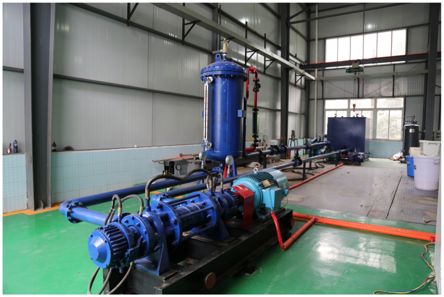
Test bench of the multiphase pump.
Test procedures
Before the experiment, the conditions of all equipments were checked to make sure they are ready. The experiment was conducted in the following procedures: starting the cooling pump, starting the water supply pump, starting the multiphase pump after water is filled to 2/3 of the mixing tank, starting the compressor after the speed of the multiphase pump is stabilized, measuring the flow rate, the pressure difference at the inlet and outlet, the speed and the torque, and then calculating the external characteristics of the multiphase pump.
External characteristics
The tested results are compared with the numerically simulated results, as shown in Figure 4. It can be seen that the error between them is within the scope of 5%. The numerical results are in good agreement with the tested results, so the validity of the simulation model is guaranteed.

Comparison between tested results and numerically simulated results.
Calculation and results analysis
The unsteady flow conditions in the pump at the non-cavitation and critical cavitation conditions (NPSHa = 8.0 m) under the gas volume fraction of ϕg = 0.1 (user-defined) were calculated. Cavitation is mainly occurred on the first-stage impeller. The further away from the cavitation area, the smaller the influence will be. Therefore, only the first-stage compression unit was analyzed.
Features of pressure pulsations excited by cavitation
To analyze the features of pressure pulsations excited by unstable cavitation flow at different positions of the pump, five monitoring points were arranged at 50% of the blade height in the computational domain. The monitoring points P1, P2, P3, P4, and P5 were located in the middle of the impeller shroud, the impeller hub, the dynamic–static interface, the guide vane, and the guide vane outlet, respectively. The positions of monitoring points for pressure pulsations in the unsteady flow field are shown in Figure 5. Then, the unsteady flow field was calculated, and the transient changes of pressure at different monitoring points were obtained.
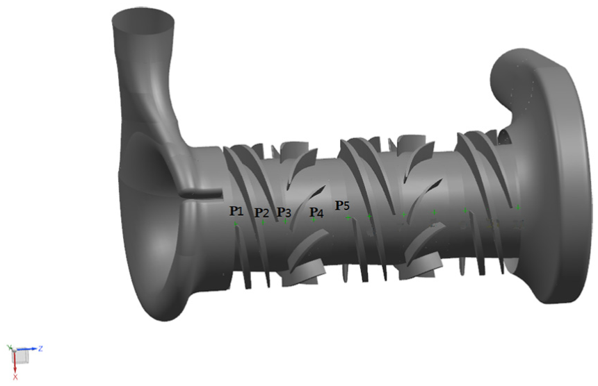
3D view of monitoring points on the first-stage compression unit.
The time domain variations of pressure pulsations in the first-stage compression unit at the non-cavitation and critical cavitation conditions are shown in Figure 6. Comparison of the time domains shows that the pressure is still in cyclical fluctuation with the impeller rotation at the critical cavitation conditions. In each cycle, a part at each valley of the pressure curve of monitoring points 1 and 2 flattens, and its pressure equals to the saturated vapor pressure of the oil phase, which means cavitation occurs at these places in these periods. With the rotation of the impeller, cavitation bubbles form and collapse periodically at these places. The amplitudes of pressure fluctuations at monitoring point 2 are larger than that without cavitation, which means that cavitation at the blade inlet has a major impact on the flow in the impeller passage. The pressure fluctuations at monitoring point 3 vary greatly, and the second wave phenomenon on the pressure curve is more prominent in one cycle. The pressure curves at monitoring points 4 and 5 do not have obvious changes, which indicate that the influence of cavitation to the flow in guide vanes is small.
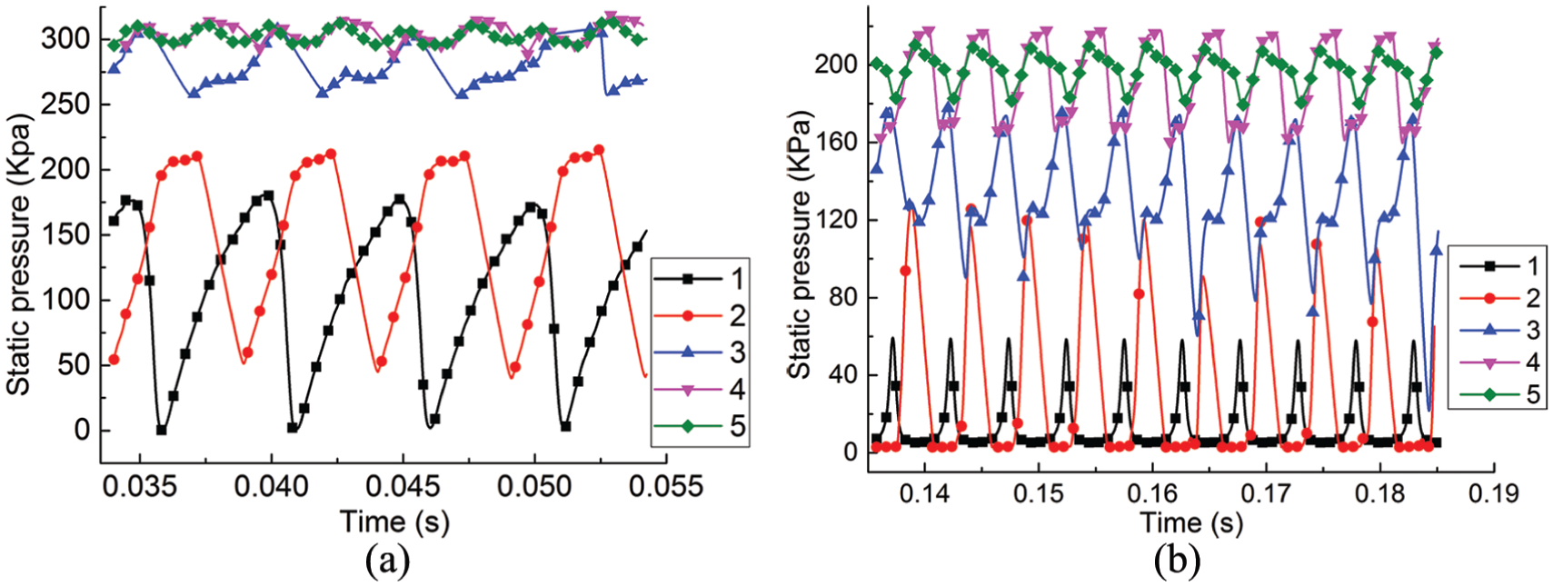
Time domain of pressure pulsations in the first-stage compression unit: (a) non-cavitation conditions and (b) critical cavitation conditions.
The frequency domain variations of pressure pulsations in the first-stage compression unit at the non-cavitation and critical cavitation conditions are shown in Figure 7. By comparing the frequency domains, it can be seen that the dominant frequencies of pressure pulsations at all monitoring points in the impeller change slightly. The dominant frequency of monitoring point 1 still equals to the blade passing frequency, that of monitoring point 2 is slightly less than the blade frequency, while that of monitoring point 3 reduces from two times to one time of the blade frequency, which indicates that the dynamic–static interaction still dominates. In addition, the amplitudes of dominant frequency at monitoring point 1 reduce, while those at monitoring points 2 and 3 increase significantly to about two times of that without cavitation, which is induced by fixed cavitation at monitoring point 1. The formation and collapse of cavitation bubbles change the inflow conditions at the first-stage impeller and produce strong impact on the blade, which aggregates the unstable flow in the impeller, and thus generates large pressure pulsations. This may also be the main cause of vibration and noise. Meanwhile, the variation degrees of the amplitude of dominant frequency at monitoring points 4 and 5 are small, which indicates the small influence of unstable cavitation flow to the pressure pulsations in guide vanes. These results show that the influence of cavitation flow to the pressure distribution in the passage of the first-stage impeller is significant, and cavitation flow will lead to the overall increase of pressure pulsations and vibration intensities in the multiphase pump. This also proves that cavitation will become the main factor affecting pressure pulsations in the pump with the intensifying of cavitation degrees.

Frequency domain of pressure pulsations in the first-stage compression unit: (a) non-cavitation conditions and (b) critical cavitation conditions.
Dynamic features of the pump excited by cavitation
Variation of transient axial force on the impeller
The variations of transient axial force on the impeller of the multiphase pump at the non-cavitation and critical cavitation conditions are shown in Figure 8.
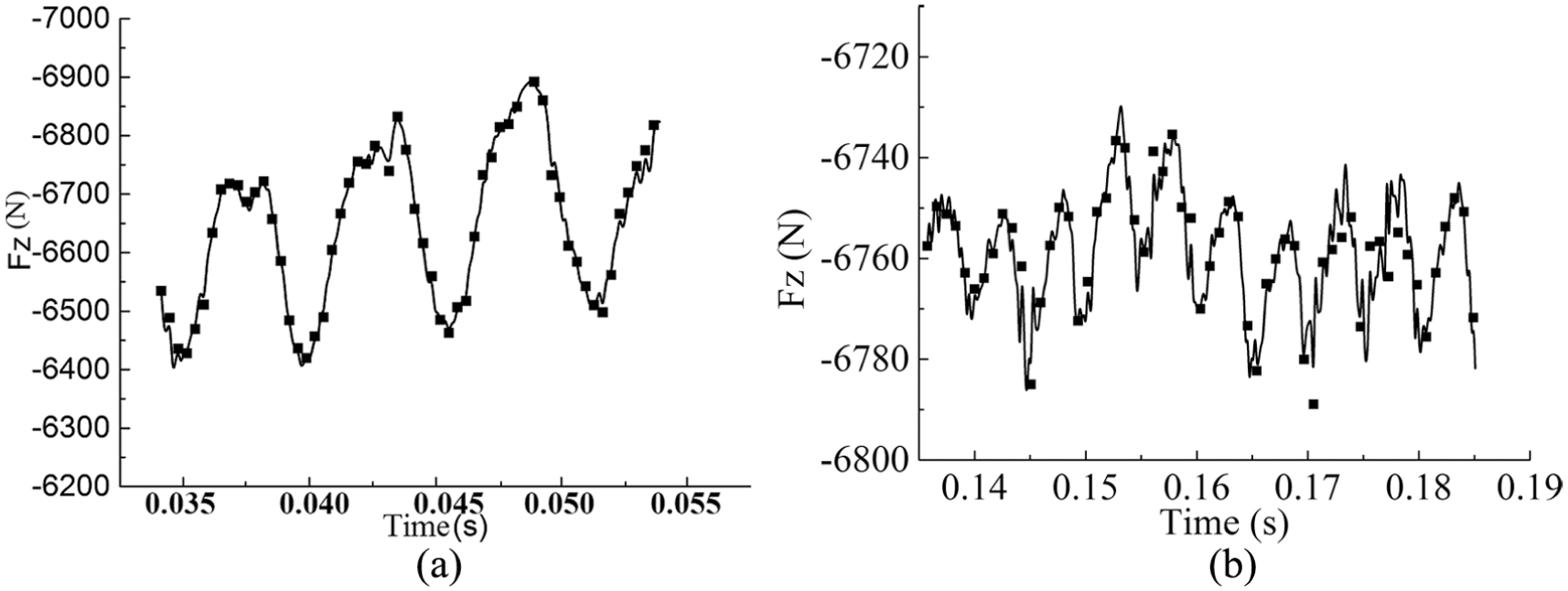
Variations of transient axial force on the first-stage impeller: (a) non-cavitation conditions and (b) critical cavitation conditions.
Compared with the non-cavitation conditions, cavitation bubbles change with the rotation of the impeller at the critical cavitation conditions. The formation and collapse of cavitation bubbles nearly double the variation frequency of axial force on the pump, but the number of peaks and valleys is still consistent with the number of blades. The axial force on the pump is slightly higher than that at the non-cavitation conditions, and it is increased by 2.7% from 6590.7 to 6769.8 N. The reason is that cavitation bubbles form and collapse on the suction surface, while there is no cavitation on the pressure surface during cavitation flow in the pump. The distributions of pressure and pulsation are changed on both sides of the blades in the passage, which in turn changes the magnitude of axial force and the frequency. The result is faster variation frequency of axial force but smaller amplification of magnitude as shown in Figure 8.
Variation of transient radial force on the impeller
The variations of transient radial force on the first-stage impeller at the non-cavitation and critical cavitation conditions are shown in Figure 9. It can be seen that the magnitude and the direction of radial force on the impeller change with time due to the variation of relative positions between the impeller blade and the stationary parts. The radial force is shaped like a star when the impeller rotates in one cycle. The variation amplitude of radial force at the critical cavitation conditions is much larger than that at the non-cavitation conditions. The maximum values and minimum values of radial force on the impeller are 62.2 and 10.8 N at the non-cavitation conditions, while 78.5 and 3.3 N at the critical cavitation conditions. Compared with the non-cavitation conditions, the maximum value of the radial force is increased by 26% and the variation amplitude of the radial force is increased by more than 40%. These results show that cavitation bubbles at the impeller inlet intensify the unevenness of flow in the impeller and increase the pressure pulsations on the circumference of the impeller, which enlarges the radial force on the impeller and increases its variation amplitude.

Variations of transient radial force on the first-stage impeller: (a) non-cavitation conditions and (b) critical cavitation conditions.
Cavitation-induced vibration
The influence of cavitation on the pump performance is shown in Figure 10.

Schematic diagram of influence of cavitation on pump performance at various stages.
The cavitation development process in the impeller is shown in Figure 11. It can be seen that cavitation bubbles are generated on the suction surface of the blade inlet near the hub due to the low local pressure caused by flow around the inlet. If the absolute pressure on the suction surface is lower than the vaporization pressure, the liquid phase will change into vapor phase. Due to the work done by the blade to the fluid, the pressure of the fluid will increase as it flows through the impeller. If the ambient pressure is larger than the vaporization pressure, the vapor bubbles will collapse.

Distributions of cavitation bubbles in the impeller at different cavitation conditions: (a) cavitation generation, (b) critical cavitation, (c) critical cavitation fracture, and (d) cavitation fracture.
The frequent generation and collapse of cavitation bubbles occur at the blade inlet. With the worsening of the cavitation degree, the impeller passage will be filled by bubbles, which blocks the energy exchange between the impeller and the fluid. During the cavitation fracture condition, the hydraulic performance of the multiphase pump drops steeply. The pump will be damaged if operating in this condition for a long time. The unstable cavitation induced by the frequent generation and collapse of cavitation bubbles will induce pulsations of the internal flow field. The circumferential pressure pulsations may even increase the torque on the pump shaft and lead to the accident of shaft fracture.
Conclusion
Cavitation in multiphase pumps will change the inflow conditions of the impeller, produce strong impact on blades, and aggregate the unstable flow in the impeller, thus generate large pressure pulsations. However, the influence of unstable cavitation to the flow and pressure pulsations is small in the guide vanes. Cavitation accelerates the variation frequency of axial force on the multiphase pump, but its influence on the magnitude of axial force is small. Meanwhile, cavitation intensifies the uneven distribution of flow in the impeller as well as the pressure pulsations on the circumference of the impeller, which in turn enlarges the radial force and increases its variation amplitude. The instability of flow induced by cavitation will intensify the pressure pulsations and induce changes to the dynamic features of the multiphase pump, which will make vibration and noise even worse. These results can facilitate the improvement of the operating conditions and provide references for studying the mechanism of vibration and noise induced by cavitation flow in multiphase pumps.
Due to the limitation of research conditions, the numerical computation method is mainly used to study the pressure pulsation features and the dynamic features. Researchers can use the visualization method to further study the unsteady excitation characteristics induced by cavitation in the future. In addition, simplifications of the liquid part and vapor part are made in this article, so researchers can modify the full cavitation model by considering the difference between petroleum and water.
Footnotes
Appendix 1
Handling Editor: Jan Torgersen
Declaration of conflicting interests
The author(s) declared no potential conflicts of interest with respect to the research, authorship, and/or publication of this article.
Funding
The author(s) disclosed receipt of the following financial support for the research, authorship, and/or publication of this article: This work was supported by the Scientific Research Project of the Education Department of Sichuan, China (grant number: 18ZB0560) and the National Natural Science Foundation of China (grant number: 51279172).