
Abstract
The flow inside axial-flow type multi-phase pumps is unstable at the conditions of high-speed and high gas volume fractions. The transient dynamic characteristics induced by the unstable flow will lead to pump vibration. Using the standard k–ε turbulence model, the standard wall equation, and the structured grid division technology, the transient dynamic characteristics of the pump at different gas volume fractions were computed by the SIMPLEC algorithm. The axial force and radial force on the pump were calculated by applying integral to the surface area of the computational domain. The results show that the pressurizing performance of the impeller degrades, the dynamic reaction on the blades decreases, while the force acting on the hub increases with the increasing of gas volume fractions. If the gas volume fraction reaches to a certain value, the direction of axial force on the multi-phase pump will change. The radial forces on the first- and last-stage impellers are non-uniformly distributed, and the pressure fluctuation is obvious, while the radial forces on the second-stage impeller and guide vanes are uniformly distributed, and the fluctuation amplitude is small. With the increasing of gas volume fractions, the radial forces on various components decrease gradually.
Keywords
Introduction
Fossil oil and natural gas are important power sources and industrial chemicals. As two strategic materials, they are widely used in industrial, agricultural, military, domestic, and other fields. However, the R&D of pump valves and other machines for the transportation of oil and gas after exploitation has always been an important issue and a difficult subject. The axial-flow type multi-phase pump developed in recent years can directly transport the crude oil and natural gas together. The use of simplified separation process of oil and gas in a single pipe instead of complicated oil and gas measurement station and double pipe greatly reduces the loss of light fraction in the oil and gas, shortens the construction cycle of the oilfield platform, and reduces the mining cost of oilfield with high gas volume fractions as well as the investment of supporting facilities.1–3
During the exploitation process of oil and gas, the axial-flow type multi-phase pump usually works under the conditions of high-speed, high gas volume fractions and large variation of gas volume fractions, which make the flow in the pump unstable.4,5 Large axial force and radial force will be generated on the pump impeller which will cause vibration and affect the operation safety of the pump and the normal exploitation process.6–8 Therefore, the accurate predication of pump’s dynamic characteristics is very important in maintaining the stable operation of the pump.
With the development of computational fluid dynamics technology, it is possible to numerically study the transient dynamic characteristics of pumps, and there are quite a few relevant studies. Bhatia 9 and Shi et al. 10 theoretically analyzed the generation mechanism of axial force, predicated the axial force of a submersible pump at different flow rates, and verified the reliability of the numerical calculation by comparing with the axial force tested on the prototype. Salvadori et al. 11 analyzed the generation mechanism of axial force in multi-phase pumps, studied the variation pattern of axial forces on various impellers at different flow rates, and analyzed the influence of leakage flow to the axial thrust. Si et al. 12 numerically analyzed the unstable cavitating flow and found that the radial force on the impeller increases with the worsening of the cavitating degree, so does the axial force. Jing et al. 13 studied the influence to transient radial force of centrifugal pumps by relative positions of the guide vanes and the tongue. By comparing with the tested external characteristic curve, he found that the closer the guide vanes to the tongue, the larger the radial force on the impeller, and the lower the efficiency. Currently, the researches on axial-flow type multi-phase pumps are mainly concentrated on the improvement of the hydraulic efficiency and the understanding of the gas-liquid two-phase flow mechanism.14–16 Using the numerical modeling results of transient flow in an axial-flow type multi-phase pump and by applying integral to the surface pressure of the computational domain, the axial force and radial force on the pump were obtained, and then the dynamic characteristics of the pump were analyzed. The analysis of transient dynamic characteristics of the axial-flow type multiphase pump can provide a new reference for studying the mechanism of vibration and noise at different gas volume fractions. It also has certain reference value for the optimal design of the structure of multiphase pumps.
Numerical model
Control equations
The working media in this research are oil and natural gas, where oil is the main phase and gas is the second phase. The basic equations are as follows:
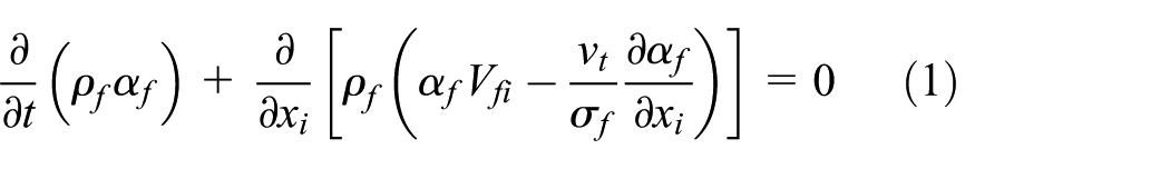
Mean continuity equation of the oil phase
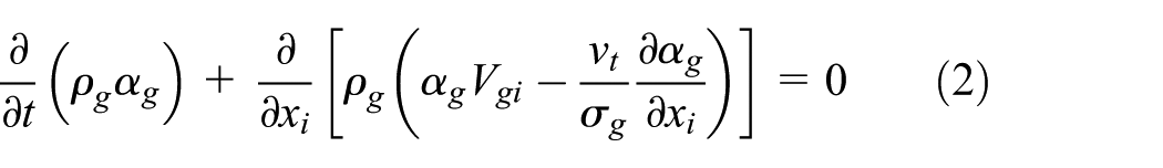
Mean continuity equation of the gas phase
Mean momentum equation of the oil phase

Mean momentum equation of the gas phase
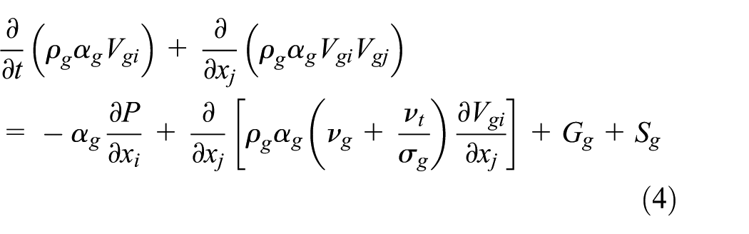
where t is the time; ρ is the density; α is the volume fraction; V is the velocity; ν is the coefficient of kinematic viscosity, νt is the turbulent kinematic eddy viscosity (νt = Cμk2/ε, Cμ ≈ 0.09); σf and σg are turbulent Schmidt numbers of the oil and gas phases, separately, σf ≈ 1.0, σg ≈ 1.0; P is the pressure; G is the interphase term; S is the source term; Gf + Gg = 0, αf + αg = 1; subscripts i and j are tensor coordinates; f and g represent oil and gas, separately.
Turbulence equations
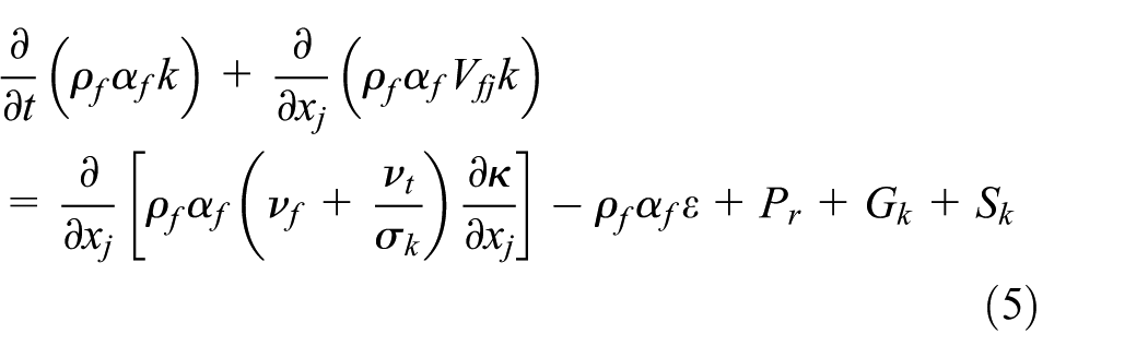
Turbulent kinetic energy k equation
Dissipation rate of the turbulent kinetic energy ε equation

where Pr is the turbulence generation term; Gk represents the turbulence kinetic energy generated by the average velocity gradient; σk and σε are turbulent Prandtl numbers of the k, ε equations, σk ≈ 1.0, σε ≈ 1.3, Cε1 ≈ 1.44, Cε2 ≈ 1.92, and Cε3 ≈ 1.3.
Calculation model of axial force and radial force
The axial force Fz and radial force Fr are calculated by applying integral to the grid area on the surface of the computational domain
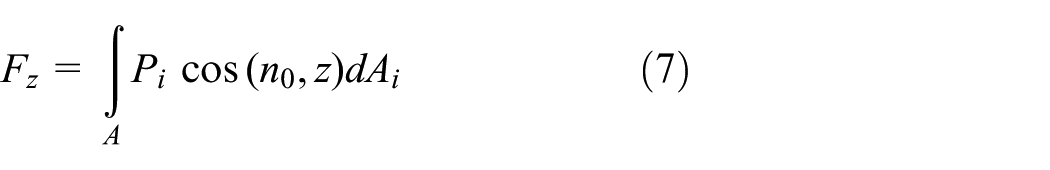


where Pi is the pressure on the grid cell, Ai is the area of grid cell, and n0 is the normal direction of the grid cell surface.
Geometric model and computational grid division
Design parameters of the pump
The pump used in this research is a three-stage axial-flow type multi-phase pump, which is composed by the suction chamber A0, the three-stage compression units A1–A5 (the compression unit is composed by the impeller and guide vanes), and the delivery chamber A6, as shown in Figure 1. The design parameters of the pump are as follows: flow rate Qd = 110 m3/h, head H = 90 m, speed n = 2950 r/min, efficiency η = 45%, scope of gas volume fraction αg = 0–0.73, oil density ρf = 910 kg/m3, number of impeller blades = 4, and number of guide vanes = 9.

Computational domain of the three-stage axial-flow type multi-phase pump.
Division of computational grid
The oil and gas flow in the compression units is the focus of this study. The structured grid was used for the impeller and guide vanes, the O-type grid was used to densify the blade surfaces, the unstructured grid was used for the suction chamber and delivery chamber, while the sliding grid technique was used to solve the multistage coupling problem between the rotating impeller and adjacent stationary guide vanes. According to the variation pattern of the hydraulic performance with the number of grids, the grid independence was verified when the variation rate of efficiency is less than 0.5%. The value of y+ (a dimensionless coefficient reflecting the grid scale on the wall boundary layer) on the blade surface of the computational grid was 50. The numbers of grids determined in this calculation are 855,534 for the suction chamber, 692,624 for the delivery chamber, 528,219 for the impeller, and 461,768 for the guide vanes.
Computational boundary conditions
Inlet boundary conditions: given the velocity inlet and the gas volume fraction at the inlet, and assuming the gas and liquid phases are uniformly distributed at the inlet. Outlet boundary conditions: given the average sectional pressure and all walls can meet with the no-slip conditions. Assuming that the media temperature is constant during the flowing process, and no cavitation exists in the pump.
To accurately calculate the transient flow process in the multi-phase pump, the steady-state results were used as the initial values, and the time step was taken as 0.113 μs.
Calculation and result analysis
The standard k–ε turbulent model was used to calculate the turbulent flow in the pump, the SIMPLIC algorithm was adopted for the coupling calculation of velocity and pressure, the standard wall equation was used to take into account the influence of the boundary layer, and the axial force and radial force were obtained by applying integral to the area of grid node on the surface of the computational domain. The conditions with gas volume fractions of 0%, 10%, 20%, 30%, 40%, 50%, 60%, and 70% were calculated in this study, but only three typical conditions (low gas volume fraction of 10%, medium gas volume fraction of 40%, and high gas volume fraction of 70%) were analyzed in this article.
Axial force on the impeller
The variation of the average static pressure on the axial face of the three-stage compression units at different gas volume fractions is shown in Figure 2. It can be seen that the overall trend of the static pressure curve is increasing from the pump inlet to the outlet. Due to the diffuser effect of guide vanes, the pressure in the guide vanes slightly increases, too. As affected by the dynamic–static interaction and the limited number of blades, the average static pressure reduces at the dynamic–static interface. The higher the gas volume fraction is, the smaller the reduction of static pressure will be. This indicates that the increasing of the gas volume fraction reduces the density of the two-phase media, and the small kinetic energy results in small hydraulic loss. However, with the increasing of gas volume fractions, the gas phase in the impeller will gather and form stable bubbles which will block the flow section and affect the flow. Thus, the pressurizing performance of the impeller will be degraded and the static pressure of flow media will be increased. By comparing the pressurization in the impeller at different gas volume fractions, it can be seen that the pressurizing process of the mixed media mainly occurs at the former half of the blade, and the effective pressurizing length on the impeller shortens with the increasing of gas volume fractions. This is caused by the increasing of gas volume fractions at the second half of the impeller hub and the gradual extension of stable bubbles toward the impeller inlet, which blocks the contact between the impeller and the liquid phase, and reduces the energy exchange between the impeller and the media.

Variation of average static pressure with gas volume fractions on the axial face of the three-stage compression units.
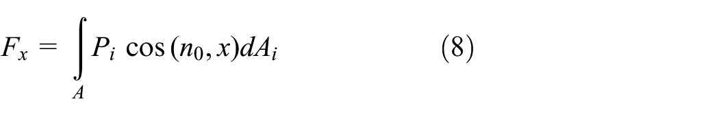
Figure 3 shows the variation of the transient axial force on the multi-phase pump at different gas volume fractions. The results show that the transient radial force varies within the scope of 3% of the average axial force during the rotating process of blades, so the fluctuation amplitude is small. The variation patterns of axial force with time at different gas volume fractions are similar. The number of peaks and valleys within a rotating cycle is the same as the number of blades, but the periodicity is not obvious. Furthermore, with the increasing of gas volume fractions, the average transient axial force on the pump reduces at first and then increases after direction change.
Variation of transient axial force on the multi-phase pump at different gas volume fractions: (a) αg = 0.1, (b) αg = 0.4, and (c) αg = 0.7.
Figure 4 shows the variation of axial force on impeller surface with gas volume fractions. It can be seen that the axial force on blades reduces with the increasing of gas volume fractions. The reason is that the two-phase flow becomes more complicated and the number of vortices is increasing with the increasing of gas volume fractions. Cavitation bubbles form and collapse frequently on the suction surface, while there is less cavitation on the pressure surface. Therefore, the pressure difference at both sides of the blade reduces, which in turn reduces the axial force on the blade pointing toward the impeller inlet. The degrading of pressurizing performance in the pump leads to the rising of static pressure of the fluid media in the compression units. Therefore, the force acting on the hub by the static pressure of the fluid media increases, and the direction of this force is toward the impeller outlet. If the gas volume fraction is less than 45%, the axial force on the blade is larger than that on the hub, so the total axial force points toward the impeller inlet, but if it increases to 45%, the direction of the total axial force begins to change toward the impeller outlet with the reducing axial force on the blade and the increasing axial force on the hub. Therefore, the transient variation of gas volume fractions has a great influence on the axial force of the multi-phase pump.

Variation of axial force on the impeller surface with gas volume fractions.
Variation of transient radial force on the impeller
The condition with the gas volume fraction of 40% was selected to analyze the causes of radial forces on various components at different stages. The pressure distributions on the circumference of the dynamic–static interface are shown in Figure 5. It can be seen that the pressure on the circumference of the impeller inlet interface varies cyclically, and the pressure fluctuation has four cycles when the impeller rotates for 360°, but the pressure distribution on the impeller at the intermediate stage is more uniform. The peak is at the head of the blade indicating local rising of regional pressure caused by small flow impact at the blade head. It also indicates that the suction chamber provides good inflow conditions for the first-stage impeller. The pressure distribution on the inlet interface of guide vanes is relatively uniform, which means that the velocity circulation existed at the impeller outlet reduces the flow impact on the guide vane inlet to a certain degree, so that the hydraulic loss is reduced. The pressure on the interface between the last-stage impeller and the delivery chamber gradually decreases and then suddenly increases, and the circumferential pressure distribution is more non-uniform.

Pressure distributions on the circumference of the middle section of the dynamic–static interface.
The variation of transient radial force (reflected by Fx and Fy) with gas volume fractions on the impeller is shown in Figure 6. When the impeller is rotating, the radial force on the first-stage impeller is mainly distributed in the first and second quadrants, that is to say the radial force points toward the tongue of the suction chamber. It is clear that the non-uniform distribution of radial force is caused by the unstable circumferential flow due to the interference between the impeller and the tongue. The distribution of radial force on the second-stage impeller is uniform, which indicates the uniform circumferential flow on the impeller. The radial force on the last-stage impeller is mainly distributed in the second quadrant, that is to say the radial force points toward the tongue of the delivery chamber. When the impeller rotates for one cycle, the variation of radial force on the first-stage impeller has four cycles, the variation of radial force on the second-stage impeller has nine cycles, while that on the last-stage impeller does not have a clear cycle. The asymmetry suction chamber and delivery chamber will affect the inflow of the first-stage impeller and the outflow of the last-stage impeller, which in turn will make the flow rate, velocity, and pressure distribution on the blade asymmetrical. With the increasing of gas volume fractions, the variation pattern of radial force is the same, but the radial force is reducing.

Variation of transient radial force with gas volume fractions on the impeller: (a) αg = 0.1, (b) αg = 0.4, and (c) αg = 0.7.
The unsteady distribution of total radial force on the impeller is shown in Figure 7. The total radial force on the first-stage and last-stage impellers is in asymmetrical octagonal star distribution. This is caused by the constant changing of relative positions between the impeller blade and the tongue. The total radial force on the second-stage impeller is in enneahedral distribution, and the number of angles is the same as the number of guide vanes, which indicates that the radial force on the intermediate impeller is related to the guide vanes. The radial force on all of the three-stage impellers reduces first and increases later. The fluctuation of radial force on the impeller near the pump inlet is large, while the radial force on the intermediate impeller is uniform and small indicating uniform flow on the circumference of the intermediate flow passage. The large radial force at both ends of the shaft is liable to cause torque increase on the pump shaft. Together with the small tip clearance in multi-phase pumps, the shaft deformation will cause impingement of the blade and the pump casing, equipment wear, and even shaft broken.

Unsteady distribution of total radial force on the impeller.
Variation of transient radial force on guide vanes
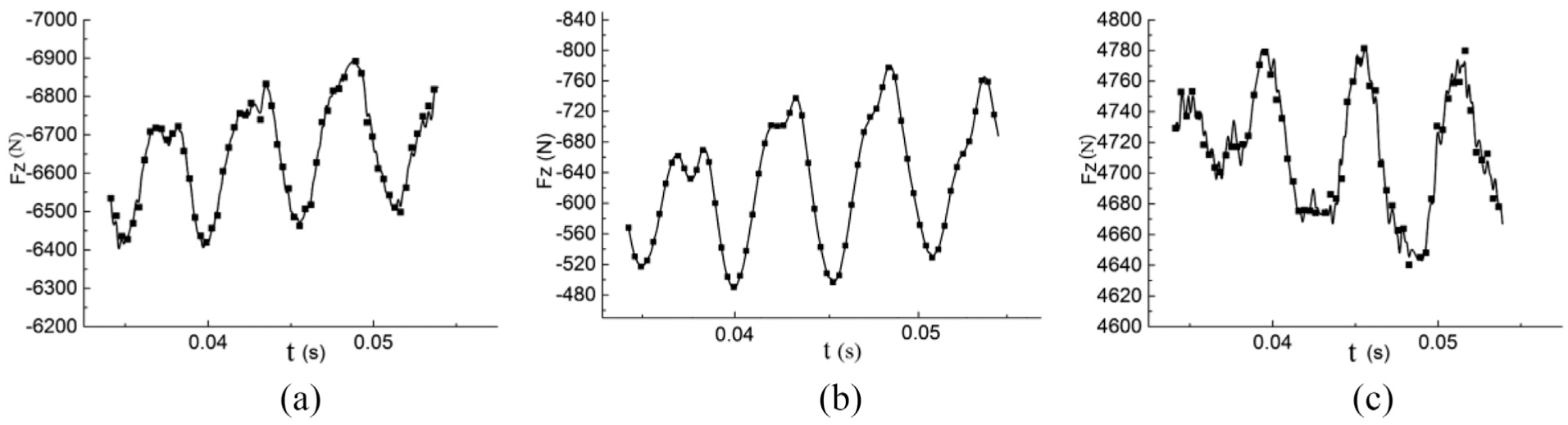
The variation of transient radial force (reflected by Fx and Fy) on guide vanes with gas volume fractions is shown in Figure 8. The distribution of radial force on guide vanes is uniform. As affected by the non-uniform flow in the first-stage impeller, the radial force on the first-stage guide vanes is in elliptical shape at first. When the impeller rotates for one cycle, the variation of radial force on guide vanes has nine cycles. With the increasing of gas volume fractions, the radial force on the first-stage impeller reduces, so the influence to the flow weakens in the guide vanes, and the variation of radial force gradually becomes a circle. After further weakening of the non-uniform flow by the second-stage impeller, the radial force on the second-stage guide vanes is uniformly distributed in a circle. The variation trend of the radial force is the same as that of the second-stage impeller and is stable. It is clear that the non-uniform flow on the circumference of the last-stage impeller is caused by the delivery chamber rather than came from the upstream.
Variation of transient radial force with gas volume fractions on guide vanes: (a) αg = 0.1, (b) αg = 0.4, and (c) αg = 0.7.
The unsteady distribution of total radial force on the guide vanes is shown in Figure 9. The distribution of radial force on the first-stage guide vanes is more uniform than that on the second-stage guide vanes. Furthermore, the radial forces on the first-stage and second-stage guide vanes reduce with the increasing of gas volume fractions.
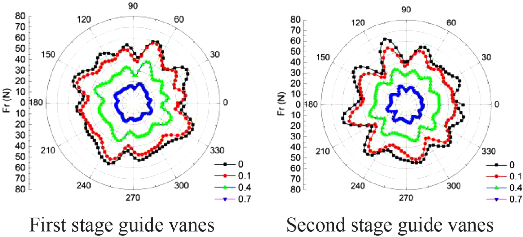
Unsteady distribution of total radial force on guide vanes.
Experimental study
Test bench
The test bench of the multiphase pump is shown in Figure 10. This is an open test bench composed mainly by the multiphase pump, the motor, the torque meter, the water supply pump, the compressor, the mixing tank, the gas flow meter, the liquid flow meter, and the differential pressure transducer.

Test bench of the multiphase pump.
Test procedures
Before the start of the experiment, the conditions of all equipments were checked to make sure they are ready. The experiment was conducted in the following procedures: starting the cooling pump, starting the water supply pump, starting the multiphase pump after water is filled to 2/3 of the mixing tank, starting the compressor after the speed of the multiphase pump is stabilized, measuring the flow rate, the pressure difference at the inlet and outlet, the speed and the torque, and then calculating the external characteristics of the multiphase pump.
External characteristics
The tested results are compared with the numerically simulated results, as shown in Figure 11. It can be seen that the error between them is within the scope of 5%. The numerical results are in good agreement with the tested results, so the validity of the simulation model is guaranteed.

Comparison between the tested results and the numerically simulated results.
Conclusion
The following conclusions are obtained through numerical modeling of the unsteady flow characteristics and the dynamic characteristics of the whole flow field of a three-stage axial-flow type multi-phase pump at different gas volume fractions:
With the increasing of gas volume fractions, the effective pressurizing length of the impeller shortens, and the pressurizing performance of the multi-phase pump degrades. As affected by the interaction between the rotating impeller and the stationary components, the average static pressure reduces at the interface.
The variation patterns of axial force with time are similar at different gas volume fractions, and the fluctuation amplitude is small. With the increasing of gas volume fractions, the pressurizing performance of the impeller degrades, so does the pressure difference at both sides of the blade. Therefore, the axial force on the blade reduces, while the axial force on the hub increases due to the static pressure of the fluid. Under certain conditions, the direction of the axial force may change.
As affected by the flow in the suction chamber and delivery chamber, the non-uniformity of flow on the circumference of the first-stage and last-stage impellers is large, and the fluctuation of the radial force is obvious. However, the influence of non-uniform flow to other components is small. The radial force is uniformly distributed on other components and the fluctuation is small. In conclusion, the radial force on the multi-phase pump is large at both ends while small at the middle. With the increasing of gas volume fractions, the radial forces reduce on various components.
Footnotes
Handling Editor: Yangmin Li
Declaration of conflicting interests
The author(s) declared no potential conflicts of interest with respect to the research, authorship, and/or publication of this article.
Funding
The author(s) disclosed receipt of the following financial support for the research, authorship, and/or publication of this article: This work was supported by the National Natural Science Foundation of China (grant number 51279172), the Scientific Research Project of Sichuan Provincial Department of Education (grant numbers 11ZZ001, 12204457), and the Open Research Subject of Key Laboratory of Fluid and Power Machinery (Xihua University), Ministry of Education (grant number szjj2015-026).