
Abstract
High efficiency and low vibration are two hot topics in the field of fluid mechanics. In this paper, different spiral volutes are designed for centrifugal aviation fuel pump based on Velocity Coefficient Method. Physical fields under different operating conditions are simulated by computational fluid dynamics (CFD) software that solved the Navier–Stokes equations for three-dimensional flow (3D-RANS). And theoretical and simulation values of radial and axial forces are analyzed. The unsteady pressure fluctuation based on the steady results at the monitoring point is solved and Fast Fourier Transform (FFT) is used to obtain the influence of different volutes on pressure pulsation. The influence of three volutes on is analyzed and compared with the simulation. The results show that the double volutes improve significantly the large flow efficiency of the aviation fuel pump, 20%–30% higher than that of the single volute. The doubles volute can also optimize the radial force under the off-design condition. The radial force of the single volute fuel pump is 100 N. The radial force of the two types of double volute fuel pump is between 10 and 20 N. The three types of volute have no obvious influence on the axial force. Two types of double volutes provide excellent suppression of fuel pump pulsation spikes over the full frequency range. The peak value of single volute is mainly concentrated in the low frequency area below 2000 Hz. The blade frequency (170 Hz) and frequency multiplication are the main frequencies of the pulsation and the pulsation decreases rapidly in the high frequency area. The research results provide theoretical support for the design of aviation fuel pump with low pressure pulsation.
Introduction
Aviation fuel pump is a special kind of aviation electromechanical equipment, which belongs to the core component of fuel system. 1 Aviation fuel pump is used mainly to deliver all kinds of aviation fuel and provide certain flow and pressure for engine and fuel system. It can be divided into centrifugal type, vortex type, volume type, and jet type. It also can be divided into supply oil pump, start-up pump, fuel-cooling pump, and emergency oil pump from functional form. 2 Centrifugal aviation fuel pump with impeller, volute, or guide vane is a kind of aviation fuel pump and has the characteristics of simple structure, reliable operation, high speed, small volume, large flow, stable performance, easy operation, and maintenance. In the future, fuel pump used in present aero-engine, space-engine, or fuel system will be oriented to smaller volume, bigger flow rate, and higher pressure. Therefore, it is important to study the external characteristics performance and unsteady flow characteristics of aviation fuel pump.
In recent years, many scholars using different turbulence models and PIV technique have done a lot of research on the internal flow simulation analysis of centrifugal pump. Based on SST turbulence model and large eddy simulation (LES), Wang and Wang 3 calculated the unsteady flow of a low specific speed centrifugal pump at both design and off-design conditions. Shigemitsu et al. 4 used PIV measurement to clarify the internal flow in the mini centrifugal pump and get the velocity distribution near the volute tongue. Rui et al. 5 simulated two phase flow characteristics of the centrifugal pumps with a full three-dimensional unsteady Reynolds Average Navier-Stokes (3D-URANS). Posa and Lippolis 6 carried out Large Eddy Simulations (LES) on a centrifugal pump to investigate the effect on pressure fluctuations through rotating and stationary channels by both flow-rate conditions and orientation of the diffuser blades. Jafarzadeh et al. 7 used commercial CFD code to study the effect of impeller blades number on the centrifugal pump efficiency. Li et al. 8 simulated flow pattern and hydraulic performance of a centrifugal pump impeller through the PIV method and analyzed the quantitative relationship between the local Euler head distribution and the internal flow in a centrifugal impeller. Ji et al. 9 used model turbulent cavitating flow with a mass transfer cavitation model by the Partially-Averaged Navier–Stokes (PANS) computational model developed from the RANS method and the k–ε turbulence model.
This paper solved Navier–Stokes equations for three-dimensional flow (3D-RANS) with three kinds of aviation fuel pumps by commercial simulation software. The static pressure distribution, streamline distribution, radial force, axial force, pressure fluctuations, etc. are analyzed.
Computational model
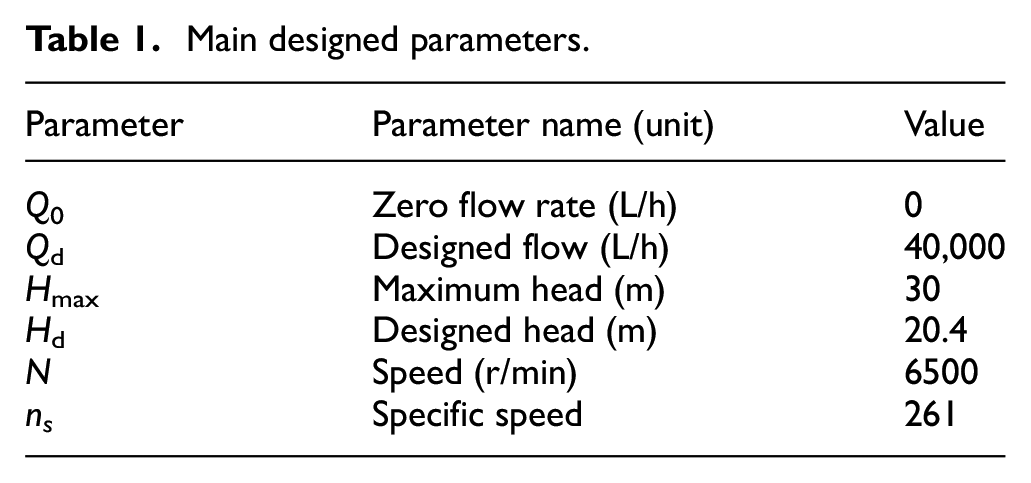
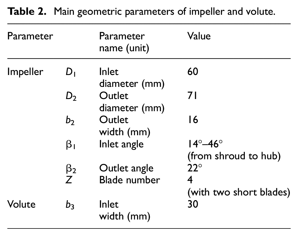
The research object is a single-suction and single-stage aviation fuel pump with a specific speed of 261. The main designed parameters are shown in Table 1. The geometric parameters of volute and impeller according to the velocity coefficient method 2 are shown in Table 2.
Main designed parameters.
Main geometric parameters of impeller and volute.
According to the reference, 2 three different types of aviation fuel pump with single volute (abbreviated as SV), double volute with short division plate (abbreviated as SDV), and double volute with long division plate (abbreviated as LDV) are designed. Four parts of calculation domain, including straight cone suction chamber, centrifugal impeller, volute, and outlet section, are created by Pro/E three-dimensional software, as shown in Figure 1.

Computational model of aviation fuel pump: (1) SV, (2) SDV, and (3) LDV.
Turbulence model and boundary conditions
The internal flow of centrifugal aviation fuel pump is three-dimensional incompressible flow and highly sufficient turbulence. The RNG k–ε turbulence model 10 is used to solve the steady single-phase problem. RNG k–ε turbulence model is a renormalization group model. The basic idea of RNG k–ε model is to treat turbulence as a transport process driven by random forces. The small-scale vortices in the RNG k–ε turbulence model are eliminated by means of spectrum analysis, and their effects are incorporated into the eddy viscosity to obtain the transport process on the required scale. The difference between renormalization group model and standard k–ε model is only C1* in the ε equation. A term is added to the ε equation to reflect the mainstream time average strain rate eij, which improves the accuracy and is better than the standard k–ε model in calculation function.
The equations of turbulent kinetic energy and turbulent dissipation rate are as follows.11,12


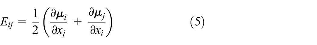
Where σ k , β, Cμ, σ ε , C1, η0, and C2 are constants. In the steady calculation, the inlet boundary condition is pressure inlet and the outlet boundary condition is mass flow. The solid wall adopts non sliding wall function, the near wall area adopts the scalable wall functions, and the frozen rotor method is used for the dynamic and static interface between impeller, volute, and inlet section, and the convergence accuracy is 10−5.
Grid analysis
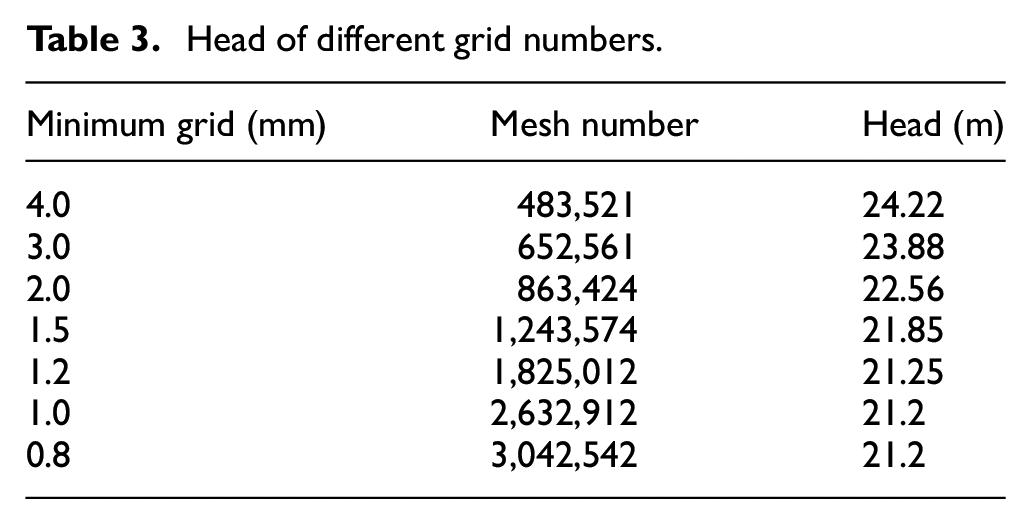
Table 3 shows the head of different grid numbers under designed conditions of SV. It can be seen that when the minimum grid number is 4.0 mm and the grid number is 483,521, the solution accuracy is the worst. When the minimum grid number is 1.0 mm and the grid number is 2,632,912, including 1,203,423 for impeller, 1,012,476 for volute, the number of grids has no effect on the calculation results. Therefore, the last set of grids is determined for subsequent calculation.
Head of different grid numbers.
Result analysis
In this paper, two equation RNG k–ε turbulence models is used to numerically calculate the internal flow of the three models under six working conditions about 10,000, 20,000, 30,000, 40,000, 50,000, and 60,000 L/h.
Steady calculation results
Performance curve
Figure 2 shows the performance curves of the three calculated models. It can be seen that when the flow rate is between 10,000 and 40,000 L/h, the SV head is larger than that of double volute, and the LDV head is the smallest, 27.5 m. The SV pump efficiency and volute efficiency are higher than those of double volutes. When the flow rate is between 40,000 and 60,000 L/h, the head defined by reference, 2 pump efficiency, and volute efficiency of LDV are higher than those of the other two, and have obvious wide high efficiency zone. When the flow rate is 60,000 L/h, the LDV head, pump efficiency and volute efficiency are 12.5 m, 72%, 93%, respectively, while the SV head and volute efficiency are in the middle.

The performance curves of the three calculated models: (1) The curves of flow rate and head, (2) the curves of flow rate and hydraulic efficiency, and (3) the curves of flow rate and volute hydraulic efficiency.
Static pressure distribution
Figures 3 to 5 show the static pressure distribution of the three calculation models. When the flow rate is 10,000 L/h, the low pressure area is located at the minimum radius of the impeller inlet, and the high pressure area is located in the diffusion section at the outlet of the volute. When the flow rate is 40,000 L/h, the maximum pressure region appears at the tongue of single volute and short double volute, while the whole volute area of long double volute is high pressure area. When the flow rate is 60,000 L/h, the highest pressure region of the three types of technical models is near the first section of the spiral case; due to the influence of the spiral case diaphragm, the highest pressure zone also appears at the diaphragm of the two types of double volute.

Flow rate, 10,000 L/h: (1) SV, (2) SDV, and (3) LDV.

Flow rate, 40,000 L/h: (1) SV, (2) SDV, and (3) LDV.

Flow rate, 60,000 L/h: (1) SV, (2) SDV, and (3) LDV.
Streamline distribution
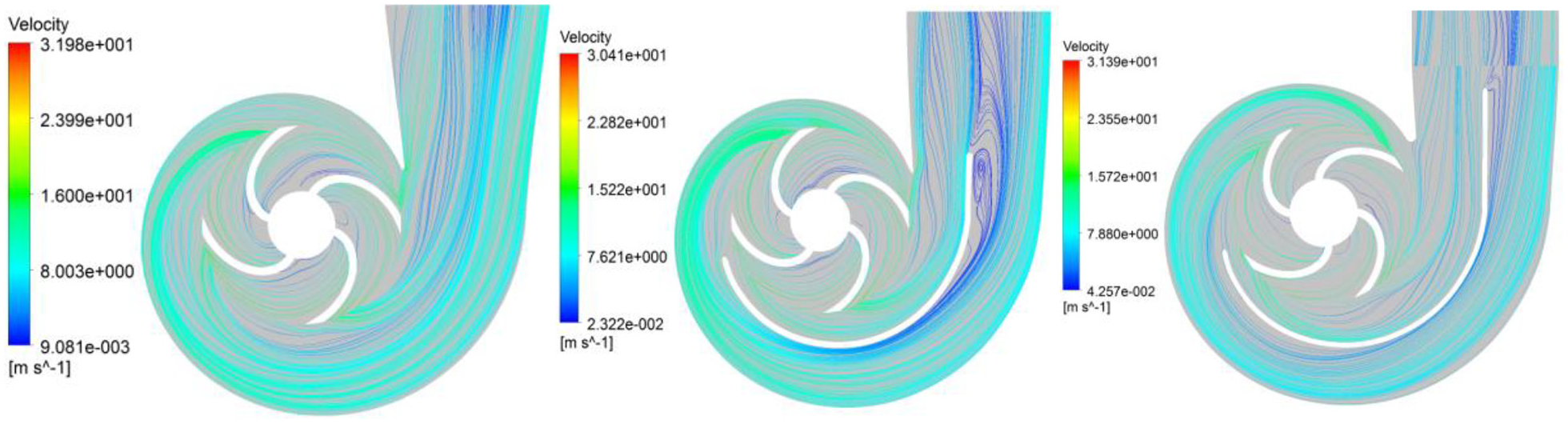
Seen from Figures 6 to 8, there are obvious axial vortices in the impellers of the three models. Due to the influence of the volute diaphragm, the streamline distribution of the two double volutes near the outside of the second spiral diffusion section is uniform and smooth. At the rated flow rate, the streamline distribution of LDV and SV is obviously better than that of SDV. Under the condition of large flow rate, there are large vortices near the tongue of the short volute, resulting in flow loss, and the streamline of LDV is still smooth.

Flow rate, 10,000 L/h: (1) SV, (2) SDV, and (3) LDV.
Flow rate, 40,000 L/h: (1) SV, (2) SDV, and (3) LDV.
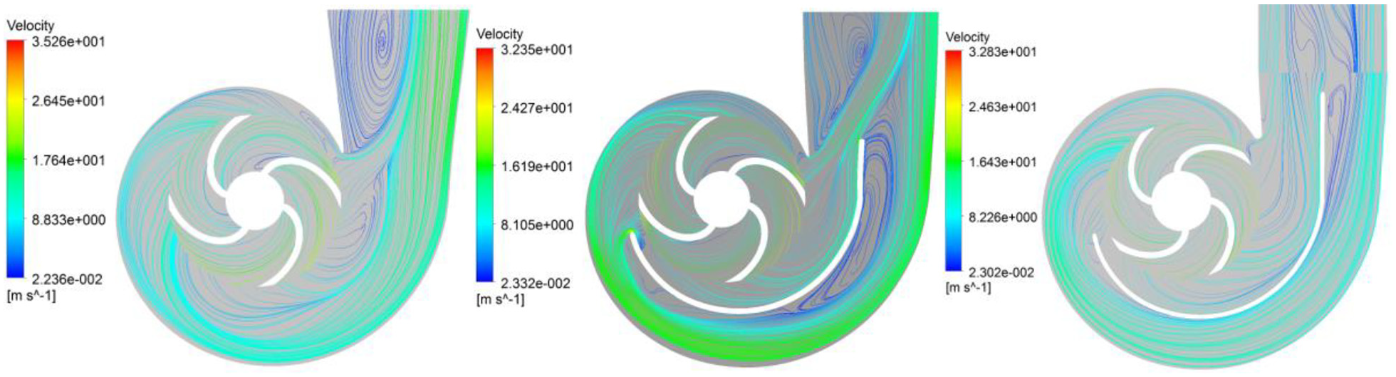
Flow rate, 60,000 L/h: (1) SV, (2) SDV, and (3) LDV.
Radial force
The static pressure distribution of the coupling surface between impeller and volute is obtained by numerical simulation of the internal flow field of the fuel pump. 13 Since the static pressure distribution of the coupling surface between the impeller and the volute is discrete, and the coupling surface is a cylindrical side. It is assumed that the static pressure is evenly distributed around each grid node of the coupling surface, and the area acting on each grid node is equal. According to the decomposition and composition theorem of forces,14,15 the force in X direction and Z direction is distributed and calculated. Finally, the magnitude and direction of the total force are obtained. The formula is as follows.

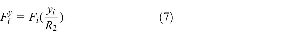
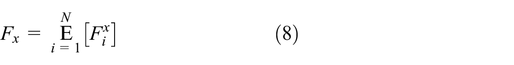


Where R2, n, FI, Xi, Yi,
The theoretical calculation formula of radial force is as follows.

Where K, H, D2, and b2 are coefficient, head, outlet diameter, and outlet width of impeller. It can be seen from Figure 9 that the influence of volute on radial force is very obvious. There is a certain difference between the numerical simulation value and the theoretical calculation value under the design condition. The radial force of SV is 40 N, and that of SDV and LDV is about 20 N. Under off design conditions, the double volute structure can obviously improve the radial force. The radial force of SV is 100 N, and the radial force of two types of double volute fuel pump is between 10 and 40 N. The theoretical calculation formula is only applicable to the centrifugal aviation fuel pump with single volute structure, and the curve path formed by theoretical calculation value and simulation value is obviously V-shaped.
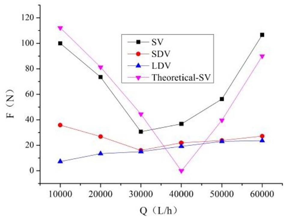
The curve of flow rate and radial force.
Axial force
The axial force generated in a centrifugal pump results from the internal pressures acting on the exposed areas of the rotating element. 16 The axial force is caused by the unbalance of liquid pressure before and after the impeller of centrifugal aviation fuel pump and the change of axial component of liquid momentum. The theoretical calculation formula is as follows.

Where Kr, H, D2, b2, ρ, and FZ are empirical coefficient, head, outlet diameter of the impeller, impeller outlet width including shroud and hub, medium density, axial force, respectively.
It can be seen from Figure 10 that the axial force also presents a V shape, but the three spiral case forms have little influence on the axial force. The axial force calculated theoretically is greater than the three calculation models, and the axial force of large flow is greater than that of small flow condition. When the flow rate is 10,000 L/h, the axial forces of the three models are about 155 N of theory, 145 N of SDV, 138 N of DV, and 127 N of LDV, respectively. When the flow rate is 20,000 L/h, the axial forces of the three models are all their minimum values. The axial force calculated by theory is close to the simulation value of single volute, which can be predicted accurately by theoretical calculation.

Curves of flow rate and axial force.
Unsteady flow analysis
In this paper, the inlet condition is set as stable total pressure and the outlet condition is set as mass flow rate. The smooth no slip wall is used for the impeller and volute, and the scalable wall is used in the near wall region. The frozen rotor interface is used for the interface between impeller inlet and inlet pipeline, impeller, and volute inlet. In order to accelerate iterative solution and reduce the solution time, a more reasonable time step is given to accelerate the convergence speed, and physical time is set to 3.211 × 10⁻³.The convergence accuracy of the solution is set to 1 × 10⁻⁵. The variation range of residuals of each detected calculation parameter with time step is 1 × 10⁻⁵. The time step is 1.61 × 10⁻⁵ s, which means one step is calculated for every 1° rotation of the impeller, and each time step is iterated for 20 times. A total of 10 cycles are calculated and the results of the 10th cycle are analyzed.
Transient radial force
Figure 11 shows that the number of sharp angles in the radial force curves of the three calculation models is equal to the number of impellers, which are 4. And the sharp angles appear in each coordinate quadrant. When the flow rate is 10,000 L/h, the maximum value of radial force is SV, followed by SDV and LDV. With the increase of flow rate, the radial force pulsation of double volute is smaller than that of single volute. The form of volute has obvious influence on the transient radial force.

Transient radial force under different flow rates: (1) Flow rate, 10,000 L/h, (2) flow rate, 40,000 L/h and (3) flow rate, 60,000 L/h.
Transient axial force
It can be seen from Figure 12 that the number of wave peaks and troughs in the radial force curves of the three calculation models is equal to the number of blades, and the wave peaks and troughs present two high and two low, corresponding to the long and short blades of the impeller. At the rated flow rate and large flow rate, the transient axial force curves of the two kinds of double volute almost coincide and are greater than that of the SV. Under the condition of small flow rate, the curves of LDV and SV are consistent, and the peaks and troughs appear synchronously. However, the transient axial force of LDV and SDV is greater than that of SV, which is a little different from that of steady calculation.
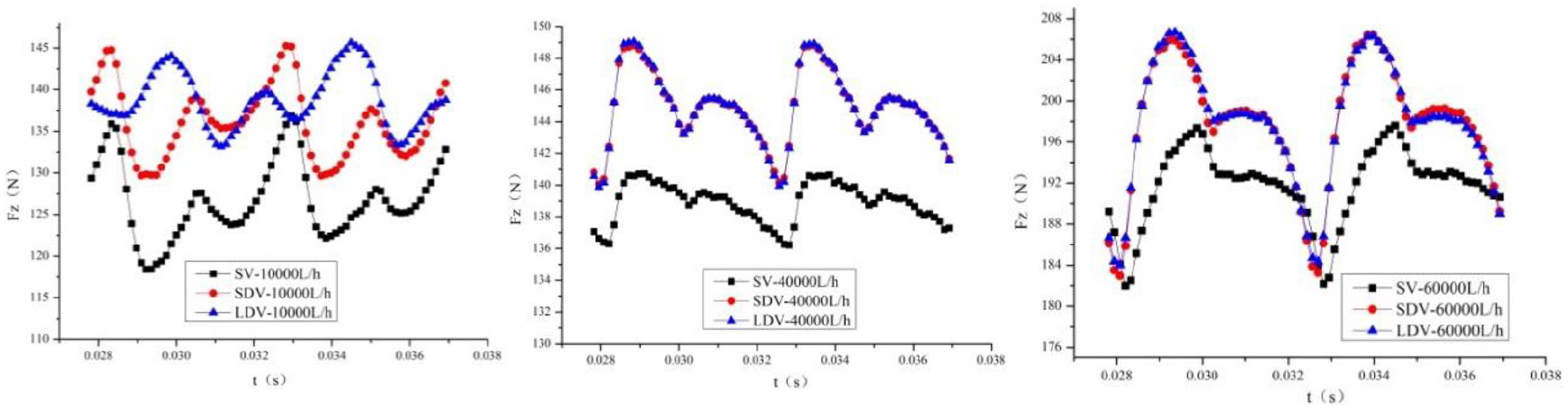
Transient axial force under different flow rates: (1) Flow rate, 10,000 L/h, (2) flow rate, 40,000 L/h, and (3) flow rate, 60,000 L/h.
Unsteady head
As can be seen from Figure 13, the peaks and troughs of the three calculation models are the same as the number of leaves. When the flow rate is 10,000 L/h, the peak and valley values of the head of LDV are smaller than those of the other two models. When the flow rates are 40,000 and 60,000 L/h, the transient head of SV is slightly higher than the other two models. The form of volute has obvious influence on the fluctuation of head curves.
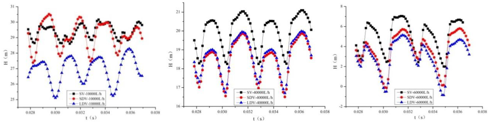
Transient head under different flow rates: (1) Flow rate, 10,000 L/h, (2) flow rate, 40,000 L/h, and (3) flow rate, 60,000 L/h.
Pressure fluctuation at monitoring points
In this paper, the pressure values of four points on the interface between impeller outlet and volute inlet and one point at volute outlet are collected for analysis. The distribution of points is shown in Figure 14.
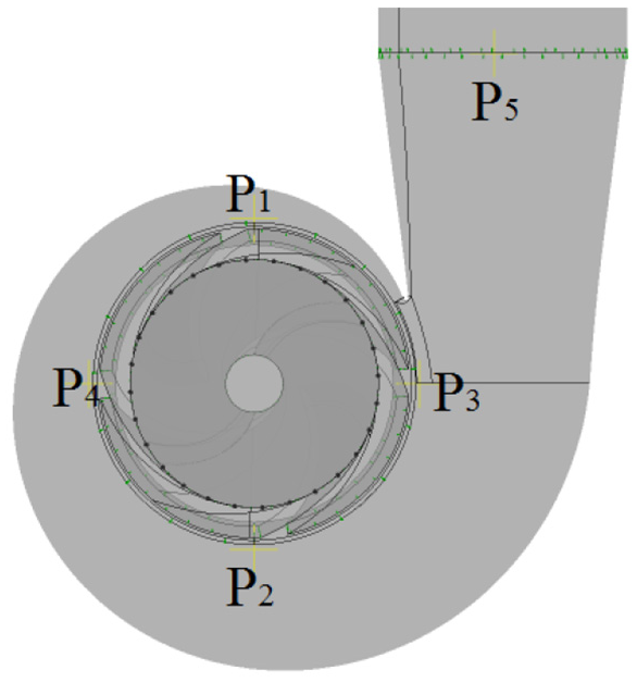
Distribution of monitoring points.
It can be seen from Figures 15 to 19 that the number of peaks and troughs presented in the pressure fluctuation curve is equal to the number of blades. When the flow rate is 40,000 and 60,000 L/h, the pressure fluctuation curves of the two types of double volute monitoring points basically coincide. Under the condition of small flow rate, only the pressure fluctuation curve of point 1 of LDV is higher than that of other points. The values of other points of SV are higher than those of two kinds of double volute in most working conditions.

Point 1: (1) Flow rate, 10,000 L/h, (2) flow rate, 40,000 L/h, and (3) flow rate, 60,000 L/h.

Point 2: (1) Flow rate, 10,000 L/h, (2) flow rate, 40,000 L/h, and (3) flow rate, 60,000 L/h.
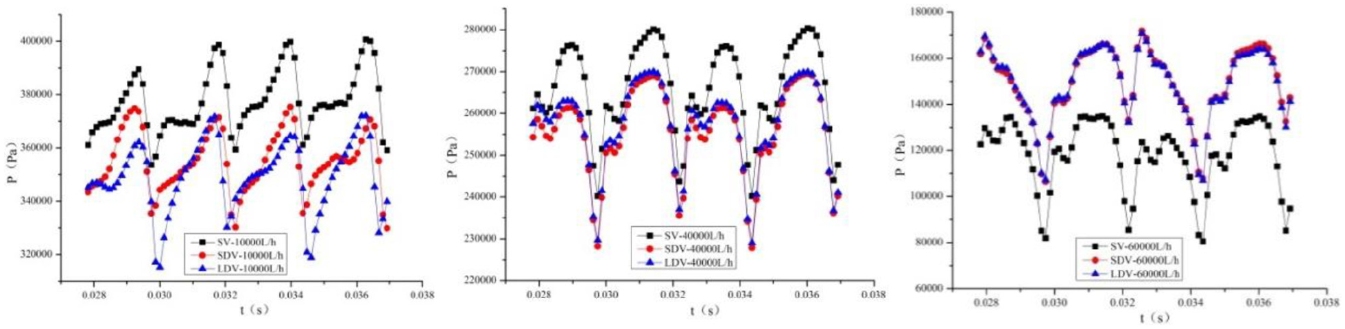
Point 3: (1) Flow rate, 10,000 L/h, (2) flow rate, 40,000 L/h, and (3) flow rate, 60,000 L/h.
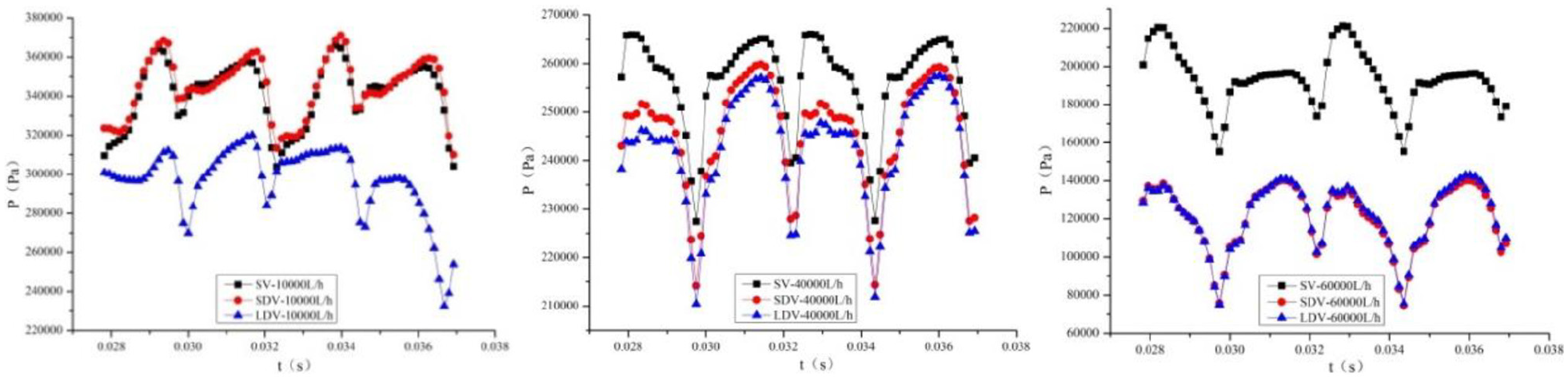
Point 4: (1) Flow rate, 10,000 L/h, (2) flow rate, 40,000 L/h, and (3) flow rate, 60,000 L/h.

Point 5: (1) Flow rate, 10,000 L/h, (2) flow rate, 40,000 L/h, and (3) flow rate, 60,000 L/h.
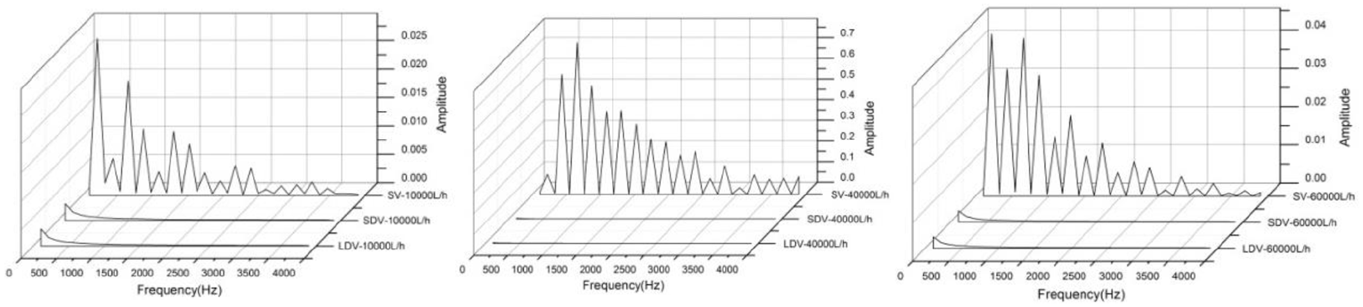
Fast Fourier Transform (FFT)17,18 is used to calculate the frequency domain diagram of pressure pulsation values in Figures 15 to 19. It can be seen from Figures 20 to 24 that when the flow rate is 10,000 L/h, the frequency domain value of point 1 of the two double volute models is smaller than that of SV. In other points, the frequency domain of the two kinds of double volutes does not show peak under different working conditions. In contrast, the peak value of single volute is mainly concentrated in the low frequency region below 2000 Hz, and the blade frequency 170 Hz, and frequency doubling are the main frequency of pulsation, and the pulsation is rapidly weakened in the high frequency region. The two types of double volute can restrain the pressure fluctuation well in the whole frequency range.
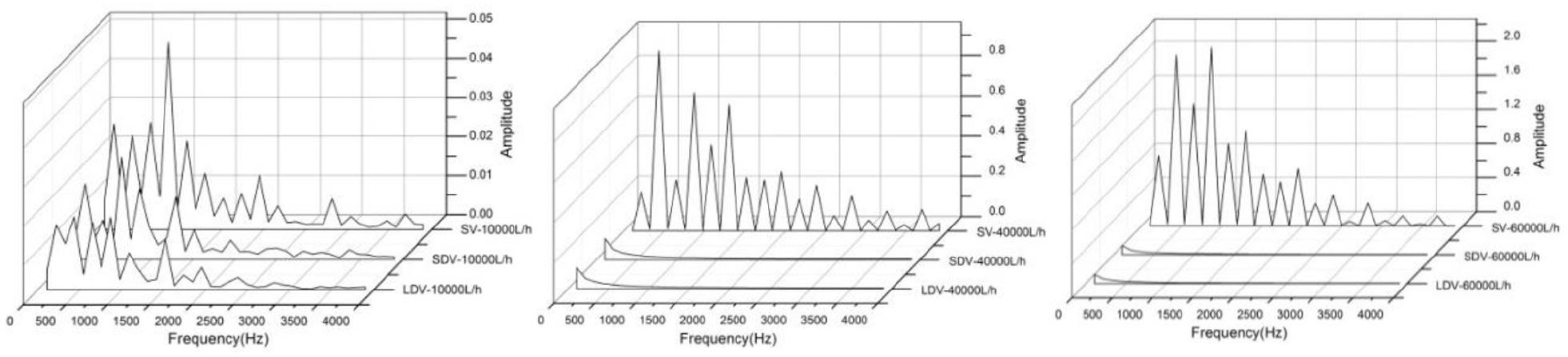
Point 1: (1) Flow rate, 10,000 L/h, (2) flow rate, 40,000 L/h, and (3) flow rate, 60,000 L/h.

Point 2: (1) Flow rate, 10,000 L/h, (2) flow rate, 40,000 L/h, and (3) flow rate, 60,000 L/h.
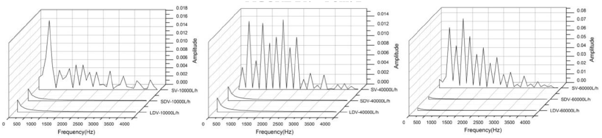
Point 3: (1) Flow rate, 10,000 L/h, (2) flow rate, 40,000 L/h, and (3) flow rate, 60,000 L/h.
Point 4: (1) Flow rate, 10,000 L/h, (2) flow rate, 40,000 L/h, and (3) flow rate, 60,000 L/h.

Point 5: (1) Flow rate, 10,000 L/h, (2) flow rate, 40,000 L/h, and (3) flow rate, 60,000 L/h.
Comparative analysis of numerical simulation and test results
From the above analysis, it can be seen that LDV can significantly improve the radial force, pressure fluctuation, and efficiency of the centrifugal aviation fuel pump. Based on the hydraulic model completed with LDV, the 3D modal is designed, as shown in Figure 25. The product composition is shown in Figure 26, including pump body assembly, impeller assembly, brushless DC motor, pump shell assembly, sealing ring, socket, and other parts.

Three dimensional structure model.
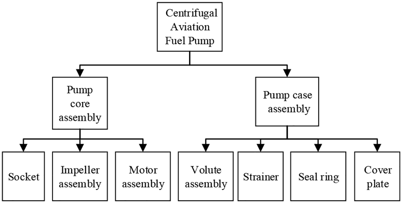
Product composition.
As shown in Figure 27, the test rig consists of 18 components including to installation flange, flowmeter connector, flowmeter connecting nut, O-ring, turbine flowmeter, stainless steel pipe, elbow, regulating valve, clamp flange, clamp, clamp flange seal ring, filter screen, pressure transmitter, pressure gauge connector, pressure gauge gasket, pressure gauge nozzle, pressure tap, pipe clamp, respectively.

Hydraulic test rig: (a) top view and (b) axonometric view.
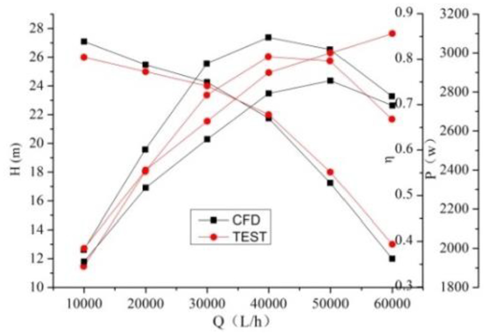
Figure 28 shows the comparison value between the test results and the numerical simulation. It can be seen that the test results of the flow head curve are in good agreement with the simulation values. Under the rated conditions, the head value is about 21.2 m, which meets the design requirements. The simulation efficiency is slightly higher than the test value, because only the loss caused by turbulence is considered in the numerical simulation process, and the mechanical damage caused by bearings and friction pairs is ignored. 19 The simulated shaft power curve has an extreme value of 2800 W, and the measured shaft power curve increases monotonically.
Simulation and test results.
Conclusion
The results show that the two types of double volute can improve efficiency of aviation fuel pump in the large flow rate, which is about 20%–30% higher than that of single volute.
Under off design condition, the double volute structure can obviously improve the radial force. The radial force of SV is 100 N, and that of two types of double volute fuel pump is about 10–20 N. Three types of volute have no obvious optimization effect on axial force.
The two types of double volute can restrain the pressure pulsation of fuel pump in full frequency range. In contrast, the peak value of SV is mainly concentrated in the low frequency region below 2000 Hz, and the blade frequency 170 Hz and frequency doubling are the main frequency of pulsation, and the pulsation is weakened rapidly in the high frequency region.
The simulation results are in good agreement with the measured values, and the changes of flow head curve and flow efficiency curve are consistent. The centrifugal aviation fuel pump with LDV meets the design requirements.
Footnotes
Acknowledgements
The authors would like to thank the National Natural Science Foundation, China (Grant No. 52079118), Sichuan Provincial Science and Technology Department Project, Sichuan, China (Grant No. 2020YFH0135).
Handling Editor: James Baldwin
Declaration of conflicting interests
The author(s) declared no potential conflicts of interest with respect to the research, authorship, and/or publication of this article.
Funding
The author(s) disclosed receipt of the following financial support for the research, authorship, and/or publication of this article: Project supported by the Open Project (Project No.: szjj2019-029) of Sichuan Key Laboratory of Fluid Machinery and Engineering (Xihua University) and the Pre-research Projects (Y2049, Y2050) of Aviation Industry Chengdu Kaitian Electronics Co., Ltd.