
Abstract
Robot acceleration is the bottleneck for high-speed pick-and-place operations. In this article, the extreme acceleration at null velocity is proposed to characterize the acceleration capability for a planar parallel manipulator having a common actuated axis, the V3 robot. Detailed dynamic model of the V3 robot is developed for computing the extreme acceleration. Since each subchain of the robot is comparable to a cantilever beam structure, its bending deflection can be considerable and thus leads to manipulation failure. Characterized by the bending deflection, the bending stiffness is thus proposed. Combining the acceleration, the bending stiffness and kinematic constraints of velocity, accuracy, and dexterity, an optimal design problem is formulated to maximize the dextrous workspace having specified desired performance. The optimized structure shows greatly improved performance in workspace, velocity, acceleration, and accuracy.
Keywords
Introduction
Thanks to their low moving mass/inertia and high acceleration, parallel manipulators have been widely recognized as prospective candidates for high-speed pick and placement of light-weight workpieces typically in pharmaceutical, electronics, food, and consumer goods industries. Great success has been achieved in commercialization since 1990s, for example, the Delta robot 1 by ABB Robotics and the Quattro robot by Adept Technology.2,3 In order to fundamentally improve the limited workspace, which is regarded as the major drawback of parallel manipulators, common-axis (co-axis for short) design was proposed for actuated joints at base. Using the parallelogram structure to eliminate rotation mobility, Brogårdh 4 first proposed a 3-degree-of-freedom (DoF) purely translational co-axis parallel mechanism in 2000. Later, it was patented 5 and named the Tau parallel robot with detailed analysis.6–8 Fully co-axis versions were presented by Brogårdh and Kock. 9 In 2010, a co-axis variation with a different arm structure was proposed for 3-DoF pure translation by Huang et al. 10 Lou et al. 11 proposed co-axis parallel mechanisms for 3-DoF planar motion in 2009. Similar structures were presented by Isaksson 12 in 2011.
The co-axis design almost fully eliminates the limited workspace drawback of usual parallel manipulators since the whole manipulator is able to rotate about a common actuated axis, which greatly enlarges the workspace to a similar level to that of serial ones. In order to further take advantage of parallel manipulators with co-axis structure, optimal design is an inevitable step since the kinematic and dynamic performances depend very much on their geometric parameters. Since 1980s, the kinematically optimal design has been extensively studied based on workspace, dexterity, manipulability, singularity, isotropy, accuracy, stiffness, force/velocity transmission, and so on, while the dynamics based optimal design remains a difficult problem for parallel manipulators. Some performance indices were proposed only based on the mass matrix in the dynamic equation, for example, the dynamic manipulability, 13 the dynamic dexterity, 14 and the dynamic isotropy.15,16 Kozak et al. 17 proposed to use the linearized natural frequency as a performance measure in dynamically optimal design of parallel manipulators. The linearized natural frequency is derived based on not only the mass matrix but also the stiffness matrix in the linearized dynamics. The first-order natural frequency is applied for optimal design of a planar 2-DoF parallel manipulator with redundant actuation. 18 For better design, more complete information in the dynamic model is used.19,20 In the dynamic design of a Delta robot, Zhao 21 proposed to minimize the maximum input torque and power given the required maximum speed and acceleration. The normalized inertial and centrifugal/Coriolis torques of single actuated joint were taken into account in optimal design of a 2-DoF translational pick-and-place parallel robot 22 and a novel redundantly actuated parallel manipulator. 23
A commercial parallel manipulator for pick-and-place applications, taking Adept Quattro as an example, performs that its maximum velocity and acceleration can achieve 10 m/s and 150 m/s2, respectively, as shown in datasheet of Adept Quattro s650H Robot. While in a typical pick-and-place task (25/305/25, in mm) with the shortest cycle time, the peak velocity of its prototype only needs to reach about 5 m/s, and the peak acceleration must be over 15g3, where its acceleration reaches the peak value while its real motion velocity is much smaller than the peak velocity value. On the contrary, the acceleration usually reaches the extremum. Nabat et al. 24 also presented a Par4 design capable of a cycle time of 0.28 s, where a large acceleration (130 m/s2) was needed while the velocity was relatively small, 3.8 m/s. Overshoot even appeared in the experiments because the actuator cannot continuously provide required torque, neither required acceleration. The R4 redundantly actuated parallel manipulator even achieved an ultrahigh acceleration of more than 100g in the pick-and-place experiment. 25 Therefore, to achieve higher efficiency, robot acceleration is the bottleneck for high-speed pick-and-place operations. However, few researches have directly applied it as a performance index in optimal design of a parallel robot because of its complexity. To obtain higher acceleration, there are fundamentally two solutions, increasing actuation torque and reducing mass/inertia of moving parts. Taking cost into consideration, the latter one is more preferable.
In this article, by taking into account both kinematic and dynamic requirements for high-speed pick-and-place operations, we propose to optimally design the V3 robot, a novel
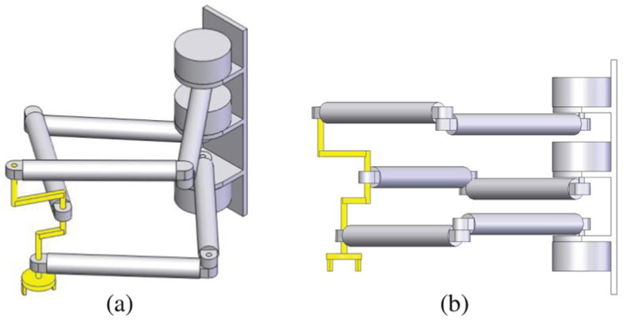
(a) The 3D model of the V3 robot and (b) side view.
The remainder of this article is organized as follows. The kinematic model and loop-closure equations are presented in section “Geometric description.” The dynamic model and the bending deflection are derived and analyzed in sections “Dynamic modeling” and “Bending deflection and bending stiffness.” The optimal design problem formulation and the optimization result are presented and discussed in section “Optimal design.” Finally, conclusions are drawn in section “Conclusion.”
Geometric description
A structural description of the V3 parallel robot is shown in Figure 2. It consists of

Notations and the coordinate system.
The variables and parameters are depicted in Figures 2 and 3 and Table 1. The V3 parallel robot undergoes the same planar motion type, 2-DoF translation in a plane and 1-DoF rotation about the axis perpendicular to the plane, as a generic planar

where

(a) An XOY projection of the V3 parallel robot and (b) the end-effector design.
Nomenclature.

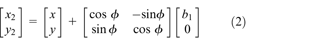
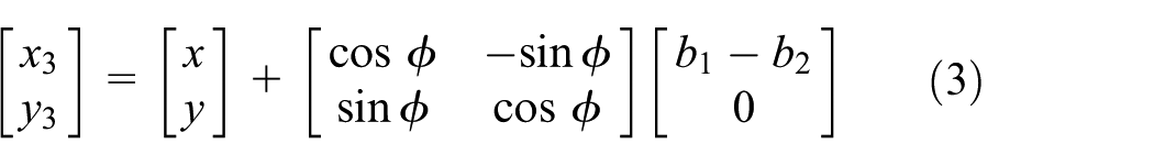
The coordinates
Acceleration analysis and dynamic modeling
In this section, the extreme acceleration capability is analyzed for optimal design of the V3 robot. Its dynamic model is then derived in detail.
Acceleration analysis
For an n-DoF non-redundant manipulator, its Jacobian matrix

where
Differentiating equation (4) with respect to time, the relation between the end-effector acceleration vector

For a planar parallel manipulator like the V3 robot, the dynamic model can be expressed in joint space as follows28,29

where

The matrix

Substituting equations (4) and (5) into equation (6) leads to the dynamics in task space relating the actuator torque to the end-effector acceleration and velocity

By left multiplying

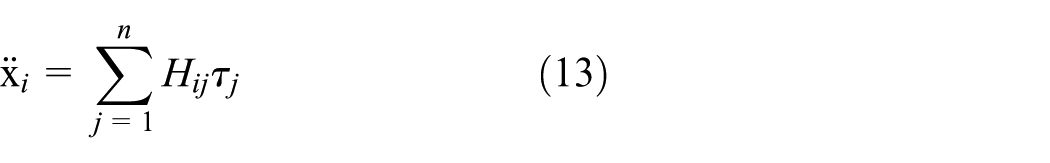
Given

where
Equation (11) provides a linear relation to compute possible end-effector accelerations depending on different configurations. Suppose that the torques are identical for all actuated joints and they are normalized by

where
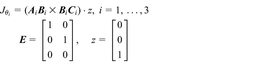
where
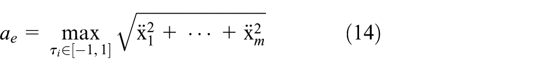
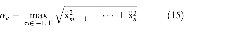
where
In order to calculate
Dynamic modeling
The modeling procedure for Delta robot
32
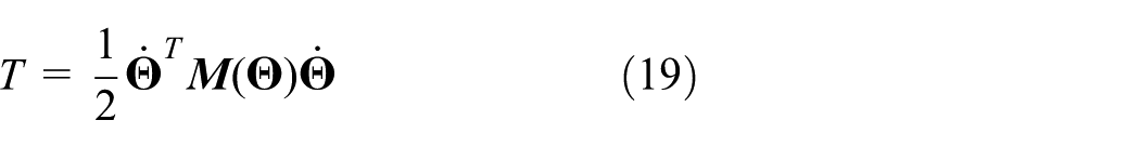
is applied to calculate the mass matrix of the V3 robot. According to Lagrangian formulation, the mass matrix of a robot can be computed from its kinetic energy. The kinetic energy of a rigid body

where

where

Substituting equations (16) and (18) into equation (17) leads to
where

From this equation, the mass matrix is formulated based on the Jacobian matrices. Thus, the main task is seeking the Jacobian matrices of the robot.
The velocity of each body can be calculated by the velocities at both of its extremities. As shown in Figure 4, the kinetic energy of the rigid bar can thus be obtained by

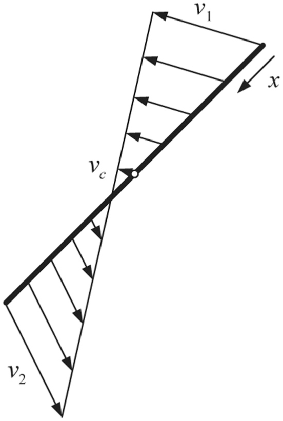
Velocities along a rigid bar.
Introducing the Jacobians

The V3 robot consists of seven moving rigid bodies, three actuated arms (the mass matrix

The contribution of the actuated arms can be readily derived as follows

where
The contribution of each passive link to the robot mass matrix can be obtained based on equation (22)

The Jacobians are presented in detail in the next section. Then, the mass matrix contributed by the three passive arms is the summation of

By direct application of equation (20) to the end-effector, its mass matrix is

where


where


Masses and inertias of the end-effector.
It is supposed that the end-effector is made up of cylinder bars with an identical radius
By combining equations (24), (26) and (27), the mass matrix of V3 manipulator is obtained as follows

Since our robot is a planar manipulator, the potential energy keeps constant during motion. Therefore, the Coriolis matrix is dependent only on the robot mass matrix. Based on Lagrangian formulation, it can be derived as follows

Substituting equations (30) and (31) into equation (6), the dynamic model of the V3 robot is thus derived.
Jacobian matrices
For the end-effector of the V3 robot, assume its translational velocity

which can be written in the form of matrix multiplication with


where we identify the Jacobians as
Before calculating the velocity of the end


where we identify the Jacobians as
The Jacobian relating the end-effector velocity vector

where

and
For convenience of representation, it is assumed that
Bending deflection and bending stiffness
Since each subchain of the V3 robot is comparable to a cantilever beam structure, especially when the subchain is in its extremely stretched configuration. The bending deformation due to gravity (robot itself and payload) may become so large that the rotation axis of the end-effector would not be perpendicular to the XY plane, which can lead to manipulation failure. In this section, the deflection of the end of each subchain is derived and is included in design.
Instead of investigating the deflection in the whole workspace, the extreme configurations are used as the worst cases to characterize the deformation. In those configurations, the bending deflections are maximum. Figure 6 shows the subchain bending model, where
Link


The subchain bending model.

The bending model of link
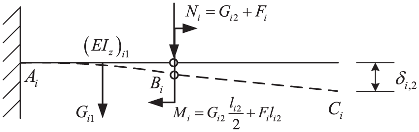
The bending model of link
The deflection due to the gravity
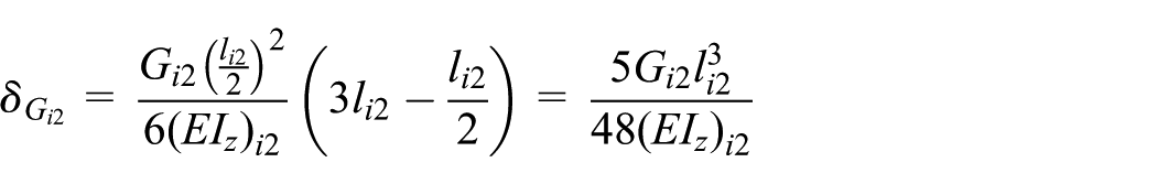
The total deflection in this case is summation of the above two parts

Link

Furthermore, the weight of the second link

The deflection and the angle deflection due to the moment
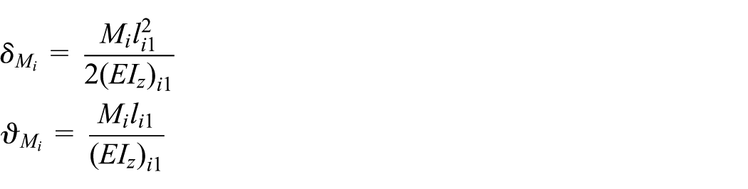
Therefore, the total deflection on the free end

where

Note that the assumption of small angle deflection is applied implicitly in the above equation. In the worst case, the maximum bending deflection of each subchain is the summation of contributions of those two cases

The quantity
Optimal design
In this section, important performance indices for a pick-and-place manipulator are presented and a design problem is formulated and solved.
Performance indices
For pick-and-place manipulations, velocity is the ultimate goal to shorten the cycle time. Due to the limited motion distance and thus the very short acceleration time, however, the velocity usually would not reach the speed upper bound imposed by actuators. The acceleration capability becomes the bottleneck to improve production efficiency. Velocity and acceleration are the crucial performance indices to characterize efficiency. Accuracy and dexterity are two additional important indices so that the manipulator is able to accomplish the task correctly and dextrously. For the special structure of the V3 robot, the bending stiffness index of each subchain is utilized to reflect manipulation properness.
The acceleration index and the bending stiffness index are presented in section “Dynamic modeling” and “Bending deflection and bending stiffness.” Brief derivation of velocity, accuracy, and dexterity indices is given as follows.
Velocity
Suppose that the velocity of each actuated joint is bounded identically

Note that the bounds for actuator velocity are normalized. Given a configuration, the extreme (or supremum) velocity can be defined as

where

Accuracy
Jacobian matrix

similar to equation (45), the independent axis error in Cartesian space can be calculated for each axis as follows

The extreme translation error


Dexterity
Dexterity index is utilized to characterize the effectiveness of the workspace. As frequently used in the literatures, the inverse condition number of the kinematic Jacobian matrix is taken to measure the dexterity of a manipulator. Since the velocities of the V3 robot have both translational and rotational components, not all the units of element in the Jacobian are the same. In order to compute the inverse condition number, a characteristic length

and the kinematics Jacobian matrix becomes

where
Note that the normalized bounds in velocity, acceleration, and accuracy indices are applied for the selection in practice. When the bounds are enlarged, the increased scales of the indices are the same. One example is in the case study.
Problem formulation
The rotational symmetry of the V3 robot architecture leads to a rotational symmetry of its performance. Its characteristics only change in radial direction. Therefore, it is not necessary to carry out performance optimization in the whole workspace. We need only to investigate the performance radially in the workspace. Without loss of generality, performances are analyzed along the radius on the
In general pick-and-place applications, the robot is required to manipulate workpieces in all orientations (excepting singular configurations). Therefore, we focus ourselves on the dextrous workspace, the set of positions with

The dextrous workspace of the V3 robot is also rotationally symmetric about the common axis. A radial workspace (e.g. along the +X-axis) is taken as the representative, which is discretized for optimization computation. When the link lengths are given, the dextrous workspace is defined. The average dexterity at a position point on the radial workspace is defined as the average of the inverse condition number of the homogenized Jacobian in full 360° orientation. Similarly, the average extreme velocity, the average extreme acceleration, and the average extreme error are defined to characterize the extreme velocity, the extreme acceleration, and the extreme error at the position point. The bending stiffness index is calculated based on the materials and geometry parameters. Given a position point on a radius in the dextrous workspace, all concerned indices are evaluated. If they all lie within given bounds, the position point is called a good point. The design objective is to maximize the number of good points, or in other words, to maximize the area in dextrous workspace having specified good performances.
According to the kinematics and dynamics, the design variable vector is

where
Optimization and results
In real implementation, the manipulator size bound is given by setting
The problem is solved using the DE algorithm,
34
a global optimization technique. In this article, all design variables are independent in the optimization problem to achieve the best performance of the V3 robot. Since there are 10 design parameters to optimize, it is time-consuming to directly carry out the search. The optimization is thus implemented in two steps. In the first step, it is assumed that the first links of all subchains are identical, that is,
Figure 9 shows computation convergence processes in the first and the second optimizations, where

The convergence of the optimizing process: (a) the first optimization and (b) the second optimization.
Table 2 shows the initial and the optimal parameters generated by the first-step optimization. Table 3 shows the final optimization results for the design parameters. It is indicated in Table 3 that the lengths of the second links in subchains tend to be identical. For the first links, however, this is not the case. The first links in the second and third subchains are longer than the first link in the first subchain, and the first links in the second subchain are the longest one. The radius of the first links is close to the double of the second ones. It also shows that the link
The initial and the optimal parameters generated by the first-step optimization (m).

The optimal parameters generated by the second-step optimization (m).


The resulting end-effector structure in the optimal design.
By the initial, the first-step and the second-step optimal parameters, it is able to compute individual dextrous workspace for each design. The corresponding inner and outer radii are respectively 0.221 and 0.553 m, 0.319 and 0.821 m, 0.236 and 0.843 m.Figure 11 shows the dextrous workspaces for the three designs, where the tori enclosed by the red solid circles, the black dashed circles, and the blue dotted circles are respectively the dextrous workspaces generated by the three resulting manipulators with the second-step, the first-step, and the initial parameters. It shows that the area of the dextrous workspace is increased by 123% and 155% by the first and the second optimization, respectively. This clearly shows the effectiveness of the optimization. Finally, the good-performance area is 82% of the dextrous workspace.

The dextrous workspace generated by the initial, the first-step, and the second-step optimized parameters.
Let us evaluate the dexterity of the optimal design radially. The configurations at a fixed point in the radial (X-axis) direction with full orientation of

The inverse condition number plot of the V3 robot with the initial parameters at

The inverse condition number plot of the V3 robot with the first-step optimal parameters at

The inverse condition number plot of the V3 robot with the second-step optimal parameters at
Figures 15 and 16 present the average extreme translational and rotational velocities and simultaneously the average extreme translational and rotational errors of each point in the good-performance radial workspace. The minimum values of the average extreme velocities are larger than the lower bounds. Since the computation expressions are identical, see equations (45) and (49), the velocity plot and the error plot should be the same shape except a multiplication of the maximum input velocity or the maximum input error. It is shown that the average extreme translational error plot touches the upper bound, which indicates that the accuracy constraints are effective. The figures show that the maximum velocities and the maximum errors appear at the same position, which coincides with our knowledge that speed and accuracy are two directly conflicting indices, that is, high speed leads to low accuracy. The maximum translational velocity/error position is at radius of 0.547 m, and the maximum rotational velocity/error is at radius of 0.519 m. Figures 17 and 18 show the average extreme translational and rotational accelerations along the good-performance radial workspace. The maximum translational acceleration position is at radius of 0.743 m, and the maximum rotational acceleration is at radius of 0.694 m.

The average extreme translational velocity and error of the end-effector.

The average extreme rotational velocity and error of the end-effector.

The average extreme translational acceleration of the end-effector.

The average extreme rotational acceleration of the end-effector.
Verification by a case study
In this section, a real actuator consisting of a motor and a gear reducer is used to compute maxima of representative indices, velocity, acceleration, and accuracy, in the constraints to verify suitability of constraint bounds. Let us consider a typical path in pick-and-place application, finishing 300 mm translation and π rad within 0.15 s. Using a triangular velocity planning scheme (Figure 19), we can compute its peak translational velocity of

The triangular velocity planning scheme.
Taking a typical actuator, Yaskawa 750W motor and a gear box with a gear ratio of 35, whose major specifications are shown in Table 4. For the actuated joint, the rated joint angular velocity is
Velocity. According to equations (45)–(47), where the actuated joint velocity is physically changed to
Acceleration. Following equations (13)–(15), the actuated torque becomes
Accuracy. The error of actuated joint is largely dependent on the error of the gear box. Here, the maximum error of the gear box is taken as the actuated joint error. In the optimal design problem, the bounds corresponding to maximum actuated joint error of
The parameters of 750W servo motor made by YASKAWA and gear box.

Through the case study above, the constraint bound settings in the optimal design problem are appropriate for high-speed pick-and-place operations.
Conclusion
In this article, the dynamic model of the V3 robot is derived for acceleration optimization. Since each subchain is comparable to a cantilever beam structure, its bending deflection is proposed to characterize the properness when manipulating workpieces. Taking the indices of velocity, acceleration, dexterity, accuracy, and bending stiffness as design constraints, the optimal design problem is formulated to maximize the dextrous workspace having specified good performance. The optimal structure shows great improvement of the good-performance dextrous workspace. It provides a good start for prototype development.
Footnotes
Handling editor: Yangmin Li
Declaration of conflicting interests
The author(s) declared no potential conflicts of interest with respect to the research, authorship, and/or publication of this article.
Funding
The author(s) disclosed receipt of the following financial support for the research, authorship, and/or publication of this article: This work was supported partially by the NSFC-Shenzhen Robotics Basic Research Center Program (no. U1713202), the Shenzhen Science and Technology Program (no. JCYJ20150731105134064, no. JCYJ20150731105106111, and no. JCYJ20160429115309834), and the Self-Planned Task of State Key Laboratory of Robotics and System (HIT) under grant SKLRS201601B.