
Abstract
In this study, the effects of a flat foot and series ankle spring on walking stability and efficiency are investigated with three passive dynamic walking models. These models are tuned on the same gait parameters to compare local and global stability with three indicators, including the largest Floquet multiplier, size of basin of attraction, and incircle of basin of attraction. Investigations show that the flat foot helps achieve better global stability on most gait parameters and better local stability near the human-like gait parameters. However, the series ankle spring degrades local stability and global stability on most gait parameters. These findings may provide an insight into the design of efficient and robust bipedal robots.
Introduction
The concept of passive dynamic walking (PDW) pioneered by McGeer 1 has been widely investigated in the past several decades2–5 for its low walking cost and human-like gait, in which both walking efficiency and stability are the major themes.
The walking efficiency is usually defined by mechanical energy cost of transport (mCOT), 3 which is mainly induced by the inelastic collisions between the foot and the ground. One direct method to cut down the cost is to use a specifically designed foot, such as rolling foot 1 and flat foot. 6 Another method is to add actuations at the right locations at the right time.7,8 Adding an energy storage device (e.g. springs) to the hip joint, 7 ankle joint,8,9 trunk, 10 and toe joint 11 can also reduce walking cost. Several models can even walk on level ground with no energy cost theoretically.8,12 This kind of solutions can be implemented passively or partially powered, without adding much complexity to the system.
Compared with the definition of efficiency, the definition of stability is quite diversified. 13 In the present context, “local stability” refers to the sensitivity of the system to infinitesimal perturbations, while “global stability” refers to the ability of the system to accommodate finite perturbations, as given in Dingwell et al. 14 McGeer 1 first analyzed the stability of the compass-like passive dynamic walkers by examining the rate of convergence, maximum allowable disturbance near the initial state of a fixed point, and jostling disturbance. Schwab and Wisse 15 found that the size of basin of attraction (BoA) of the simplest walking model 16 is extremely small, which is consistent with real prototypes’ limited ability to bear disturbance. Later, Wisse et al. 17 found that their model can sustain a disturbance of more than 8% of the initial values, much more than 2% for the simplest walking model, 15 when investigating the simplest walking model with an upper trunk. They used the hip spring to control the walking frequency and found that the hip spring stiffness is the pivotal parameter for disturbance rejection. Wisse et al. 18 also found that the area of BoA could increase significantly as long as the leg swings fast enough. This simple strategy greatly improves the global stability. Through both simulations and experiments, Mizuno et al. 19 demonstrated that energy storage device such as a spring or rubber placed between two legs can improve the walking stability of a compass-like PDW walker. Recently, Jeon et al. 20 demonstrated that the size of BoA of the simplest walking model with rolling foot or flat foot is small and the maximum slope angle and walking speed that can form stable walking are also very limited.
The flat foot, possessing a human-like shape, has the benefit of improving walking efficiency and the ability to stand still compared to an arc-shaped foot. The series ankle spring can further decrease significantly the walking cost. Wang et al. 9 used cell mapping method to get the BoA of the model with both flat feet and ankle spring of a group of default parameters, arriving at the results that the walking stability could be increased. Jeon et al. 20 have investigated three passive walking dynamic model with point feet, with curved feet, and with flat feet and obtained the fixed point of limit cycle walking of the flat foot and curved foot models of several different groups of parameters, and the BoA of curved foot models. However, the effects of the flat feet and of the ankle spring on stability have not been comprehensively investigated, such as how the effect of flat feet alone on the local stability and global stability changes as the model parameters and gait changes, how the effects of flat feet on the local and global stability vary with the length of the flat foot, and the same to the ankle spring.
In this study, three simple PDW models, one with point foot, one with fixed flat foot, and one with flat foot and ankle spring, are employed to systematically analyze the effects of flat foot and ankle spring on walking stability. The first two models with point foot and with fixed flat foot are simulated under many different pairs of model parameters, the results of which are compared to study the effects of flat foot on stability. Similarly, the last two models are used to study the effects of the ankle spring. These results may help in designing the PDW models with high efficiency while possessing high stability.
Models and methods
Models
Derived from the simplest walking model, 16 the following three PDW models are employed and investigated in this study, respectively:
PDW-I is derived from the simplest walking model, with a hip spring attached, as shown in Figure 1(a).
PDW-II is derived from PDW-I, with the point foot replaced with a locked flat foot, as shown in Figure 1(b).
PDW-III is derived from PDW-II, with the ankle joint and series ankle spring applied to the foot, as shown in Figure 1(c).

Schematic diagram of the three PDW models: (a): PDW-I, (b): PDW-II, and (c): PDW-III.
All the models are fully passive and are placed on a constant slope, actuated only by gravity. Notation of parameters of the models and their meanings are listed in Table 1. Foot length is fixed at
Nomenclature.
Mass
Both hip spring and ankle spring are linear, with no damping or friction.
The problem of foot scuffing coexisting with straight leg is ignored.
Both heel-strike and toe-strike are assumed as an instantaneous, fully inelastic impact, with no slip or bounce.
All quantities have been non-dimensionalized by the following factors: mass,
Methods
A walking step is first defined for each model, which consists of several continuous motion processes and several instantaneous collision events. The continuous motion process is solved by the Lagrange equations, while the collision process is solved by the conservation law of momentum. By combining the whole processes, the strike function is defined and its periodic fixed points can be computed. The details are as follows.
Definition of one walking step
A walking step is defined separately for each model as follows, and the key events are illustrated in Figure 2.
PDW-I: A step starts just after heel-strike collision and ends just after the next heel-strike collision. A complete step contains one continuous motion process and one heel-strike collision process. During the continuous motion process, the stance leg is connected to the ground. The model can be seen as an inverted double pendulum. The heel-strike collision occurs as the swing leg moves forward and touches the ground. After the collision, the former stance leg and swing leg are swapped immediately.
PDW-II: A step starts just after a heel-strike collision (event A) and ends just after the next heel-strike collision. A complete step includes two continuous motion processes and two collision processes. During process A-B, the heel of the stance leg is connected to the ground. As the stance leg rotates forward, the toe-strike occurs (event B) where the toe becomes the new rotating joint. Then, the stance leg continues rotating forward until the heel of the swing leg contacts the ground (heel-strike). The former stance leg and swing leg are swapped just after heel-strike collision and the next step begins.
PDW-III: A step starts just after the ankle spring of the trailing foot releases to its equilibrium position (event A). A complete step includes four continuous motion processes and four collision processes. Process A-B is the same as process A-B of PDW-II. At event B, the stance foot is flat on the ground. During process B-C, the stance foot is kept flat on the ground. At event C, the supporting force from the ground to the heel of the stance foot is zero and the heel is about to lift. During process C-D, the toe of the stance foot is connected to the ground and the model has 3 degrees of freedom. As the swing leg moves forward, the heel-strike occurs. Afterwards, there is a double-support period (process D-A). One step ends as the ankle spring of the trailing foot releases to its equilibrium position and is about to lift from the ground.

The event sequences of one walking step for the three PDW models. The hip spring and ankle spring are omitted for simplicity.
Calculation of continuous motion processes
For each process of motion, let

where
Calculation of inelastic instantaneous collision
The heel-strike collision is generally assumed as inelastic and instantaneous, resulting in sudden changes of the state of the system. Take the heel-strike collision process of PDW-II as an example, as depicted in Figure 3.

Diagram of heel-strike collision of the PDW-II model.
Before the heel-strike collision, the hip rotates around the toe of the stance leg. After the collision, the stance leg and swing leg are swapped and the hip starts rotating around the heel of the new stance leg.

During collision, there is only an impulse acting with the ground at the heel contact point of the former swing leg, and there is no external force acting on the former stance leg. Therefore, the angular momentum of the whole system is conserved about the collision point, and the angular momentum of the former stance leg is conserved about the hip joint. By neglecting the mass of the foot compared with that of the body, we obtain the following equations
where

The other collisions can be solved in the same way.
Detection of key events and failure modes
A whole step is formed by the continuous motion processes and instantaneous collision events. During the calculation of each process, the collisions should be detected during every integration step. If a collision occurs, the former process ends and the next continuous process begins, and so on. In addition, several failure modes are also checked. These failure modes are defined according to the definitions reported by Schwab and Wisse.
15
The failure mode of falling backward is defined as the case where the angular velocity
Definition of stride function and calculation of periodic fixed points
Stride function maps the initial state of a step to the initial state of the next step. The Poincare section is defined at the start of a step on the phase plane for all the models, just after event A as shown in Figure 2. Let

The motion of the system is fully determined for a given point on the phase plane. A gait cycle is defined as the motion of system if the system returns to its initial state after k steps. If
For the given model parameters (
Calculation of the indicators of walking stability
Three stability indicators are used to measure the stability of the model. They are the largest Floquet multiplier
The largest Floquet multiplier

If
The matrix

By giving two different small
Size of BoA
The size of BoA is used to indicate global stability. The larger the size of BoA is, the better the global stability is.
A point on the Poincare section could lead to stable gait cycle, chaotic motion, or one of the failure modes. BoA is defined as the collection of points on the Poincare section that could lead to stable gait cycles or chaotic motion. It is calculated using the cell mapping algorithm.15,21 The basic idea is to divide the concerned region on the Poincare section into a large number of cells. All the cells are labeled as null initially. For a cell labeled as null, the algorithm applies the stride function to the centerpoint of the cell. If the result points to another cell labeled as null, then the stride function is applied to the other one and this process is repeated until (1) the last cell leads to one of the failure modes, and then all the cells in this list are labeled as failure mode; (2) the last cell leads to a cell that is not labeled as null, and then all the cells in the list are labeled the same as that of the cell; (3) a cell that is already in the list is encountered, and then all the cells in the list are labeled as BoA. At the end of the process, all the cells are labeled as BoA, or one of the failure modes.
The concerned Poincare section is defined as
Incircle of BoA
As the indicator “size of BoA” does not consider the relative position between the fixed point and the boundary of BoA, a third indicator called as “incircle of BoA” is proposed to further indicate the global stability. It is defined as the maximum perturbation percentage around the fixed point within the BoA and illustrates how far the fixed point is away from the boundary of BoA. For example, considering

The larger the incircle of BoA is, the better the global stability is.
Simulation results
Walking stability under human-like gait
As a first attempt, the model parameters are determined and the corresponding stability indicators are computed for all the models under the same human-like gait, respectively. Walking speed is given as
Model parameters and the corresponding stability indicators under human-like gait.

PDW: passive dynamic walking; BoA: basin of attraction.

BoA, fixed points, and incircle of BoA for (a) PDW-I, (b) PDW-II, and (c) PDW-III under human-like gait successively. The maximum incircle of BoA is depicted by a red circle.
The results show that PDW-II consumes about half the energy compared to PDW-I, while PDW-III consumes only one-quarter energy compared to PDW-I. The required hip spring stiffness
The stability of the three models differs significantly. PDW-II has the best local stability and global stability. PDW-III has the worst local stability. It also has the smallest incircle of BoA despite its relatively large size of BoA. Its fixed point is closer to the boundary of BoA, as shown in Figure 4. Therefore, the results show that the flat foot improves the stability, while the ankle spring may worsen the stability. We will discuss it further in the following two subsections in detail.
Effects of flat foot on stability
In this subsection, PDW-I with point foot and PDW-II with flat foot are compared to investigate the effects of the flat foot on the three indicators of stability mentioned above. First, with the same geometry except the foot, the two models with different pairs of the slope angle
Pairs of model parameters to obtain the same gaits for comparisons
For these two models, each pair of model parameters (defined by
To fully investigate the effects of the flat foot on stability, it is reasonable to compare the stability of PDW-I and PDW-II under a great number of the same gait parameters. Given a combination of
A sampling of 20 different stiffness

where
For a given

where
In this research, the minimal slope angle
Comparison of the two models with different gait parameters
Bifurcation appears as the slope angle increases for both models when
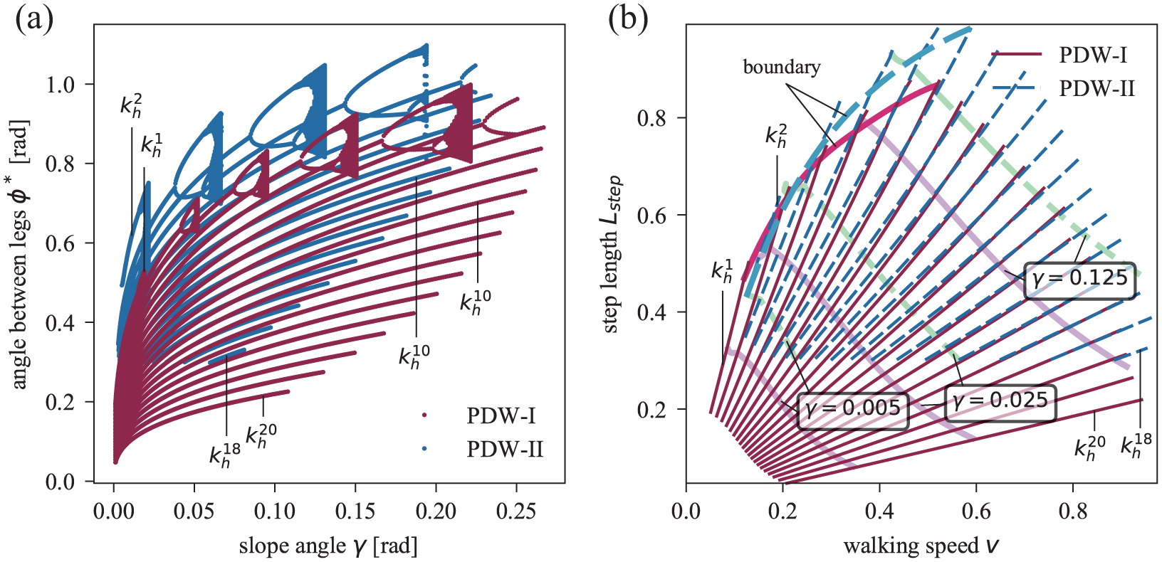
Information of stable gait cycles and chaotic motions for different hip spring stiffness and slope angles. (a) The
Walking frequency is almost fully determined by
After the fixed point has been obtained, each sampling list

Contours of the three stability indicators of PDW-I and PDW-II in the plane of gait parameters. Each column depicts the results of (a, d)
For both models, the local stability, indicated by the largest Floquet multiplier
These stability characteristics of the two models are further verified by contours of their differences, as illustrated in Figure 7. It confirms that the local stability of PDW-II is similar to that of PDW-I, but its local stability around human-like gait is better. The global stability of PDW-II is better than that of PDW-I for almost all gait parameters, as indicated by the size of BoA and incircle of BoA. In fact, it has been reported that the stability and the distance from the largest Floquet multiplier to the unit circle have limited correlation, 15 while the size of BoA has good correlation, so the result of the size of BoA is more convincing than that of the largest Floquet multiplier. Moreover, the results of difference in incircle of BoA a quite the same as that of the BoA, indicating that the index of the proposed incircle of BoA is very useful.

Contours of differences of the three stability indicators (a)
Effects of the length of the flat foot on stability
The above subsection investigates the stability of the flat foot by comparing the PDW-I and PDW-II in different gaits. However, the PDW-I model with point foot can be seen as the PDW-II model with zero-length flat foot. Thus, it is meaningful to vary the the length of the flat foot and study its effects on stability.
While obtaining the fixed human-like gait, a series of PDW-II models with foot length between 0 and 0.2 are simulated. The three indicators of the walking stability versus the foot length are obtained, as illustrated in Figure 8. The results show that, as the foot length increases from 0 to 0.2, the

Stability as a function of foot length for the PDW-II model. Gait parameters are fixed at human-like gait, that is,
In conclusion, the comparisons of PDW-I and PDW-II show that the flat foot can improve walking stability and also make the walking more efficient.
Effects of series ankle elasticity on stability
Similar to PDW-I and PDW-II, model parameters
For a list combination of

Energy-optimal model parameters: (a) slope angle
The stability of PDW-III indicated by the three indexes is shown in the contour plots shown in Figure 10(a)–(c), respectively. The results of PDW-III show that the local stability reaches its minimum value at a small walking frequency, so the small walking frequency could contribute high local stability. Moreover, the local stability becomes worse for a small step length. This might be the reason that no solution is found for the walking gait with a step length below 0.4. The trends of size and incircle of BoA are similar to those of PDW-I and PDW-II. Proper gait parameters benefit global stability, as indicated by the size and incircle of BoA.

Contours of the three stability indicators (a, d)
The stability differences between PDW-III and PDW-II are shown in the contour plots of Figure 10(d)–(f). The PDW-III model has a larger
Walking efficiency and stability in cases of non-energy-optimal ankle spring stiffness are also examined. For the human-like gait, the required

Effects of ankle spring stiffness on energy cost and walking stability for PDW-III. Human-like gait parameters are used (
In conclusion, although the series ankle spring improved walking efficiency on the basis of the flat foot model, it generally degrades both local stability and global stability.
Discussion
Compared with a flat foot and series ankle spring, the gait parameters have even more significant influence on walking efficiency and stability. For example, the size of BoA of the simplest walking model can increase from 0.004 to 0.26 only by adjusting gait parameters. Thus, it would be more appropriate to compare the stability of the two different models under the same gait parameters. The comparisons show that the flat foot can improve both walking stability and efficiency, while the series ankle spring can improve efficiency but somehow worsen stability. Both efficiency and stability are vital to the PDW, so it is reasonable to import flat foot and series ankle spring to improve the efficiency, but special attention should be paid to the stability, which may be worsened by ankle spring.
The size of BoA is broadly used to indicate the global stability of PDW models.9,11,15 However, it might not be used alone to indicate global stability. It does not take into account the position of the fixed point in the BoA. In some cases, the size of BoA can be large, but the fixed point might locate just near the boundary of the BoA shape, and thus the system can actually sustain only small perturbations. During our calculation of fixed point as a function of ankle spring stiffness of PDW-III, as the ankle spring stiffness decreases, no fixed point is found finally as the incircle of BoA suddenly approaches zero; meanwhile, the size of BoA is still very large and the local stability is relatively good. As a result, the size of BoA is better used as a stability indicator in conjunction with other indicators like, for example, the simple “incircle of BoA” indicator proposed in this study.
We did not carry out a fully parametric analysis for parameters such as ankle position and foot–leg equilibrium position. However, with the tradeoff of simplicity, we are able to carry out a full stability analysis in the coordinate of gait parameter. Our simulations are not intended to give absolute quantities, but an insight into the effects of flat foot and series ankle spring on walking stability.
Conclusion
It has been known that flat foot and series ankle spring can improve the efficiency of the PDW. However, their effects on local and global walking stability have not been studied comprehensively. In this article, three PDW models derived from the simplest walking model are employed to investigate the effects of flat foot and series ankle spring on walking stability. The local stability is indicated by the largest Floquet multiplier, and global stability is analyzed by both the size of BoA and the incircle of BoA, which is first proposed in this article. The two models with point foot and with flat foot are simulated and their results are compared to investigate the effect of the flat foot on both the local and global stability, while the models with flat foot and with flat foot and series ankle spring are compared for the effect of the hip spring. These comparisons are carried out in the coordinates of gait parameters, as the gait parameters have a significant influence on the stability. The positive effects of flat foot and series ankle spring on the efficiency are confirmed in our simulations, and we have made the following remarks regarding their effects on the stability.
Flat foot has a positive effect on walking stability. The local stability of the flat foot model is superior to the point foot model around the human-like gait parameter. Both the global stability indicators show that the flat foot model has a better global stability than the point foot model on almost all gait parameters.
The series ankle spring has negative effects on walking stability compared to the flat foot model, although it could aid more efficient walking. The model with series ankle spring has inferior local stability and inferior global stability on almost all gait parameters.
These results and the simulation methods may help in designing the PDW for both high efficiency and stability, which suggest that special attention should be paid to the design of the series ankle spring, because it could improve efficiency while worsening the walking stability.
Footnotes
Handling Editor: Pierangelo Masarati
Declaration of conflicting interests
The author(s) declared no potential conflicts of interest with respect to the research, authorship, and/or publication of this article.
Funding
The author(s) received no financial support for the research, authorship, and/or publication of this article.