
Abstract
Stiffness is one of the important parameters for estimating the performance of hybrid parallel robots as it is not constant throughout its workspace. The aim of this study is to provide an optimum path based on maximum stiffness within the workspace of a 9-degree-of-freedom hybrid parallel mechanism configuration, which includes nine linear actuators connecting one stationary and two moving platforms in series. The proposed robot is designed for ankle rehabilitation, where accurate and precise movement of lower extremities is required. The design takes advantage of two important characteristics of parallel robots: stiffness and workspace. The proposed methodology to determine the stiffness of hybrid robot in three single axes is based on calculation of position vector of each actuator in any particular pose, by considering the inverse kinematics of the system, in order to obtain the magnitude and direction of the applied forces. The results obtained from the workspace calculations have been compared with those of two standard parallel mechanisms including a 6-degree-of-freedom hexapod and a tripod with 3 degrees of freedom. The stiffness of the robot has been calculated in simulation and then compared with those of a developed prototype hybrid model in two different case studies.
Introduction
Stiffness and accuracy are the most important characteristics making parallel mechanisms suitable for applications such as medical operations, human–systems interaction, haptic interfaces and rehabilitation applications. Due to good size/power ratio and compact size, parallel robots are more appropriate than serial robots. Delta and hexapod are the most well-known structures of parallel robots with their kinematics and dynamics studied for decades. Usually, the stiffness of a tripod and a hexapod is determined by calculating the deformation caused by external force on the end-effector. Therefore, stiffness analysis of a parallel robot depends on the material properties and length of the actuators used. 1 In another study, the stiffness analysis of a parallel robot was determined by different parameters such as joints positions, structural architecture and end-effectors position. 2 Different researchers have calculated the stiffness of parallel robots based on a developed Jacobean matrix for different configurations.3,4 Inverse kinematics (IK) has been used in different studies to find the workspace of the parallel mechanism.5,6 Dimensional synthesis of a 3UPS-PRU parallel robot was investigated in order to reach maximum linear and angular velocity in desired workspace. 7
The robust finite-time tracking of a Stewart platform using forward kinematic solution has been developed to determine the unique length for the actuators by considering all the uncertainties and parameter variations. 8 The stiffness of a six-legged platform was studied by Li et al., 9 and calculated using IK and then compared with the results of finite element analysis (FEA). Zhang et al., 10 and Masouleh et al., 11 investigated combinational parallel mechanisms where their kinematics and dynamics calculated based on the kinematic change in the models. Due to the limited workspace of parallel robots, a new configuration (PARASURG-9M) was developed and its IK was investigated for surgery applications. 12 The hybrid or planner 3-degree-of freedom (DoF) parallel manipulator is a relatively new configuration of parallel robot which is developed to improve the limited workspace of a 6DoF parallel configuration.13,14 This made the hybrid parallel robot more efficient to use for ankle rehabilitation. 15 6DoF is needed in order to simulate the motion of the foot, but singularity and limited flexibility of the hexapod motivated us to push an idea for a new serial–parallel manipulator. The hybrid configuration is an elegant solution to increase the flexibility of the parallel robot and to achieve full range of foot motions. Hu et al., 16 studied the stiffness of various configurations of hybrid parallel robots for elastic deformation. Zhao et al., 17 developed a new formulation set up of stiffness for hybrid parallel kinematic mechanism (HPKM) in a multi-dimensional vibration isolator based on the screw theory method and the stiffness was evaluated considering compliances in different directions and the extremum values in the workspace.
Stiffness is one of the important parameters in estimating the performance of the hybrid parallel robots, particularly when the system is used as a rehabilitation device. The aim of this article is to calculate the stiffness and elastic deformation of 6-UPS-3SPR hybrid parallel robot. This article investigates the stiffness of a flexible configuration of a parallel robot by calculating the position vector of each actuator in the determined workspace of the system. This is carried out by calculating the stiffness matrix of the system. In the mathematical method, the workspace and stiffness of the tripod and the hexapod are calculated separately, and the data were combined together in order to determine the workspace and stiffness of the hybrid parallel robot. The external force applied by the foot was measured in the gait lab and the results were used in FEA. The final position and orientation of the end-effector are input data to the IK formulation in order to calculate the length of actuators. The developed formulation is based on a transformation matrix containing the rotational matrix with Euler angles and translation motion. The data are supported by experimental results tested on a robot prototype.
Methodology
Gait analysis
Fourteen participants including seven males

Simulated lower limb model of a participant during moving the left foot in (a) dorsiflexion and (b) plantar flexion directions. In the right side of both pictures, the Butterfly force profile is overlaid with the participant’s foot. In the both pictures, force plates are labelled with numbers 1 and 2 in white colours.
The captured data were processed using Vicon nexus 1.7.1, and a three-dimensional (3D) model of lower limb and profile of force were modelled. The position of the attached markers and the recorded data by the force plates were exported to MATLAB software to be filtered and normalised. A foot plane was defined by the attached markers 1, 2 and 3 that they were placed on ankle, toe and heel, respectively. By calculating the normal vector of the foot plane, the path motion of the foot was determined during ankle dorsiflexion/plantar flexion. Calculation of the normal vector of the foot segment has been explained in our previous work. 18
Kinematic mapping motion
Generally, the position of a point can be identified by a transformation matrix containing six independent quantities (linear and rotational motions in XYZ). The homogeneous transformation matrix was used to calculate the position of the end-effector along the foot trajectory. The system contains two moving platforms, as shown in Figure 2.

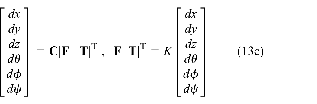
3D CAD model of 9DoF parallel robot designed in SolidWorks. The global coordinate reference of the hybrid robot is placed on the centre of platform B.
The position vector of the actuators has been calculated using a developed kinematic and transformation matrix. The stroke length of actuators is important in order to find out the velocity of the actuators. Equations (1a) and (1b) calculate the actuators vector position


where
Workspace analysis
IK identifies the positions of the platforms and the joints along the captured foot trajectory. However, applying the structural constraints of the design identifies the reachable points existing in the workspace. The stroke size and joints range of motion are the constraints considered in this study. The position of the joints on the hexapod for the motion of the ankle during dorsiflexion/plantar flexion is obtained by equations (1a) and (1b). The system contains 18 joints, and the corresponding range of motion should be determined to calculate and analyse the workspace. The angles between the actuators and joints demonstrate the motion of the joints. The angles of the joints on platform B are calculated using equations (2a) and (2b)

where


where

where
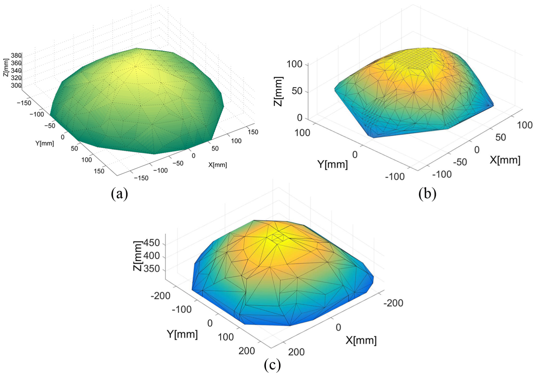
Simulated workspace of the three parallel configurations: (a) workspace of the 3-UPR tripod, (b) workspace of the 6DoF hexapod and (c) workspace of the 9DoF hybrid.
The results are based on the number of points assumed to be in the workspace; the shape of the workspace is more accurate by increasing the number of mesh nodes. The results produced by the numerical method, developed in MATLAB, suggested that the workspace of the hybrid robot is increased by
Stiffness analysis
In the Cartesian space (global frame), the pose X of the end-effector is determined by the position variables (x y z) and orientation variables

The exerted force on platform A is developed by (6)

where


where

The actuator force during the foot trajectory has been defined in a matrix format which is expressed in equation (9). Where

The relation between input and output loads of the hexapod parallel manipulator is given by equation (10)


Free body diagram of applied forces on the 3-UPR configuration.
As it is expressed in equations (12a) and (12b), the applied force and torque on the platform are balanced by three active actuator forces which are expressed by


where


Results and discussion
Finite element analysis
In this section, the displacement of the hybrid parallel robot under applied force has been simulated in SolidWorks software and the results were used to validate the theoretical method. Foot trajectory and corresponding applied force, during dorsiflexion and plantar flexion movements, were recorded by the motion capture system and the force plates in the gait lab. The recorded position and force were averaged over all participant’s trials. The results obtained for the left leg have been demonstrated in Figure 5(a) and (b). The gait results were used by the Motion Analysis toolbox in SolidWorks and the stiffness of the modelled hybrid robot was analysed while the model tracked the foot trajectories.

(a) Ground reaction forces (GRFs) in X-, Y- and Z-axes are recorded by the force plate located under the left foot, and then the corresponding values were averaged over all participants and trials. The foot moved upwards (from 0:86 s) and then moved downwards (from 0.86 s:1.49 s), then plantar flexion movement started at 1.49 s and the toe reached to its maximum height from floor at 2.11 s, and finally, foot was in the rest mode at 3.05s. (b) Position of the foot during dorsiflexion and plantar flexion.
As shown in Figure 5(a), the maximum applied forces (Fx, Fy, Fz) during dorsiflexion and plantar flexion were (8.12 N, 1.46 N), (17.15 N, 1.28 N), (69.48 N, 36.57 N), respectively. With respect to the calculated deformation of the CAD model under load, the stiffness of the hybrid parallel robot is calculated in SolidWorks during tracking the foot motion. As it is shown in Figure 6(a), the deformation of components has been calculated separately in three axes of X, Y and Z. The solid mesh type with curvature base and four Jacobian points with the mesh size of 0.3 mm were used in the FEA. The element size and tolerance were 0.497 and 0.024 mm, respectively. In addition to the material properties of the actuators and joints, other mechanical properties of the robot have been considered in the simulation, such as physical structure, position and orientation of the end-effector. Based on the hypothesis of this study, the centre point of the foot is placed on the centre point of platform E. The

Translational stiffness analysis of hybrid robot in simulation: (a) deformation of actuators under load and (b) translational stiffness along X-, Y- and Z-axes during dorsiflexion and plantar flexion.
By starting the dorsiflexion movement, the force profile has been shifted from the calcaneum towards the toes. The maximum deformation has been observed when the foot is in neutral position. Figure 6(b) shows that stiffness in the Z-axis has been sharply decreased once dorsiflexion motion completed and it has been reached to its minimum at 24 kN/mm when the heel was removed from the floor, and the calcaneum reached its maximum height from the floor.
A prototype of the hybrid robot was modelled and built in order to validate the simulation results. In the following section, the stiffness of the robot prototype is investigated during execution of different motions.
Experimentation validations
A hybrid robot was built using nine servo linear actuators, with stroke size of 10 cm, connecting to the platforms by universal joints. The hybrid robot created by combination of a 3DoF robot and a 6DoF robot. The six universal joints used on platform A are capable of rotating around themselves. The platforms are made by aluminium (Alloy 2024). In order to measure the applied forces, nine 6-axes Nano25 force sensors were embedded between the universal joints and clevises. A SSC-32 Servo Controller was used to control and receive force and position feedback. The developed prototype of the hybrid robot is shown in Figure 7. The 3D CAD model of the system, when the foot is placed on the platform, is depicted in Figure 7(b).

(a) The built 9DoF hybrid robot prototype and (b) 3D CAD model of the foot placed on the hybrid platform for ankle rehabilitation.
Protocol of experiment
The experiment was designed to determine the translational stiffness of the robot following the foot trajectory. The required actuator lengths to follow the foot trajectory were calculated by the IK and data were sent to the microcontroller to execute the motion. The calculated actuator lengths during the exercise are shown in Figure 8. Results show a higher contribution of the tripod than hexapod in tracking the foot motion by the end-effector.

Length of actuators during tracking the foot motion. Actuators [1, 2, 3,…, 6] correspond to the hexapod configuration and actuators [1, 2, 3] correspond to the tripod configuration.
In order to measure the displacement of the system, the built robot was loaded with 7 kg calibration weight and the position of the robot was recorded while it was tracking the foot trajectory. Then, this value was compared with the corresponding value of unloaded robot and displacement of the robot was calculated in X-, Y- and Z-axes. The maximum ground reaction force recorded in the gait lab was 69.48 N along Z-axis, so it was decided to use similar external force in the experiment, and therefore, 7 kg weight was loaded on platform E. This experiment was repeated over 10 trials and the averaged displacement was calculated along three axes.
The applied forces on the actuators in three axes were measured by the embedded force sensors while the robot was loaded with 7 kg weigh. The Nano25 recorded Fx, Fy and Tz with 3600 Hz, and Fz, Tx, Ty with 3800 Hz. The measured forces were averaged separately for the hexapod, the tripod and in overall for the hybrid robot. The stiffness of the prototype was calculated along three axes and the results are depicted in Figure 9(a). Based on the coordinate system used in the gait lab, the X-axis was defined as a pivot axis during the exercise.

(a) Stiffness analysis of hybrid robot during performing dorsiflexion and plantar flexion movements and following the recorded foot trajectory and (b) Stiffness error between simulation and experimental results.
Figure 9(b) shows that the maximum stiffness error between simulation and experimental results was 5.5%, 6.6% and 4.3% in X-, Y- and Z-axes, respectively. As it is shown in Figures 6(b) and 9(a), the stiffness had a similar pattern in both simulation and experiment. In simulation, the external force was changing with respect to the time, while the external force was constant in experiment and this issue was recognised as the main source of error. It is worth mentioning that increasing the mesh size will improve the accuracy of the results in simulation.
Another case study was designed in order to investigate the stiffness behaviour of the robot when there is a constraint in Z-axis and robot moved only along X- and Y-axes. The stiffness matrix is determined as a scalar value which is attributed to the stiffness of the system. This makes the comparison easier for different configurations in the same particular position. As it is shown in Figure 10, this value was calculated when the end-effector was fixed in
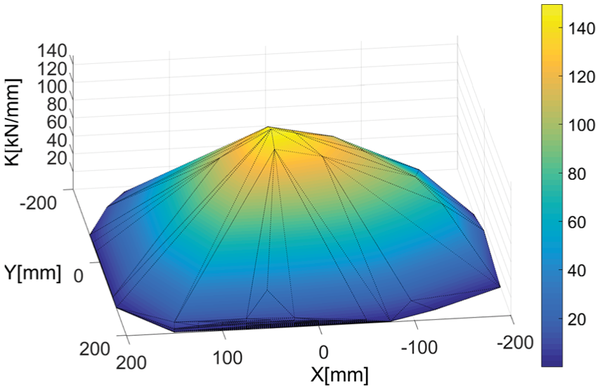
Stiffness of the hybrid robot when the end-effector was fixed in
The results approve the high stiffness of the 9DoF hybrid parallel robot and capability of the robot to be used as an assistive robotic device for ankle rehabilitation. This robot, as an alternative solution for traditional ankle rehabilitation, provides more accurate movements with respect to the range of motion of patient’s joints. In future work, the stiffness of the system in more complex motions will be investigated and results will be used to optimise the design and structure of the hybrid robot.
Conclusion
This article presents a new configuration of parallel robot with increased workspace for rehabilitation of the ankle. By analysing the workspace of the robot, it was found that the robot has the capability of tracking the foot motion within the reachability range of the end-effector. Accordingly, the results show that the workspace of the hybrid parallel robot has significantly increased by
Footnotes
Acknowledgements
The authors would like to thank West Midlands Rehabilitation Centre (WMRC) and University College London (UCL) for their support. Alireza Rastegarpanah and Hamid Rakhodaei are identified as joint lead authors of this work.
Handling Editor: Tadeusz Mikolajczyk
Declaration of conflicting interests
The author(s) declared no potential conflicts of interest with respect to the research, authorship, and/or publication of this article.
Funding
The author(s) received no financial support for the research, authorship, and/or publication of this article.