
Abstract
With the development of cities, more high-rise buildings continue to emerge. Regular cleaning of building exterior walls is necessary, which mainly relies on manual work now. In this article, the planar four-cable-driven parallel robot (CDPR) is adopted to carry out the external cleaning of high-rise buildings. Firstly, the kinematic model and static model are established. The influence of the maximum cable force on the workspace is analyzed, and the position of the cable connection points on the end effector is discussed. Then, the stiffness of the CDPR is analyzed, which reveals that a large difference of the width-to-height ratio between the end effector and the base improves the stiffness condition number and average stiffness of the CDPR. Considering the size of the cleaning module, the horizontal cross layout is adopted and cable connection points are determined. The cable force range is discussed considering the variable size of the base. Finally, the prototype of a cable-driven cleaning robot is designed accordingly.
Introduction
With the population concentration and urban development, more and more high-rise buildings appear. Glass is often used for decoration of exterior walls of high-rise buildings, and the demand for external wall cleaning is increasing. At present, the cleaning work mainly relies on manpower. The workers suspend themselves outside the building through safety ropes or stand on the suspended platform to clean the external wall, which is labor-intensive and dangerous. Therefore, scholars and engineers began to seek to design automated robots to clean the building’s exterior walls. Attempts using climbing robots for exterior wall cleaning were proposed. 1 Mir-Nasiri et al. 2 proposed a window-climbing robot with pneumatic suction cups should be able to move autonomously along an outside surface of window and meantime clean it. Vega-Heredia et al. 3 designed a robot named Mantis for cleaning windows on building exterior walls. The Mantis robot was composed of three modular climbing units and was able to move across obstacles from one window to another. Climbing robots usually adopt magnetic or vacuum adsorption, and can only be applied to metal or smooth surfaces. Their motion ability is also limited. The application of drones is limited by stability and load capacity. Besides, manual remote operation is usually required for the above robots. Efficient and highly automated approaches for exterior wall cleaning of buildings need to be further developed as an important part of service robots. 4,5
The cable-driven parallel robot (CDPR) adopts cables instead of rigid links to drive the motion of the end effector, which brings the advantages of high load capacity, small motion inertia, good dynamics, large workspace, reconfigurable, as well as low manufacturing cost. The CDPRs have been successfully applied in the wind tunnel experiment, 6 high-speed sorting, 7 large radio telescope, 8 architecture construction, 9 and so on. The reconfigurability, low cost, and large workspace of the CDPRs well meet the requirements of exterior wall cleaning of buildings, and CDPRs can carry out the automated operations, showing great application potential in this field.
To expand the movement ability, cable-driven cleaning robots were designed inspired by the suspended cable-driven structure of artificial cleaning. For example, Lee and Chu 1 designed a new cleaning robot by adding a cable structure to the pneumatic suction robot to achieve vertical motion. Seo et al. 10 used a similar design and developed the ROPE RIDE cleaning robot. However, only the vertical movement ability was expanded. To improve work efficiency, Joo et al. 11 designed cleaning platform with a large horizontal size. A rope-driven parallel structure was used to achieve the vertical movement of the cleaning platform. Jiang and Zhang 12 designed a planar two-cable-driven cleaning robot, but it is an underactuated structure with poor rigidity. In summary, there is no cable-driven cleaning robot that can move flexibly in two directions and cover a large area of flat space. In this article, a cable-driven cleaning robot is going to be designed.
The workspace is an important parameter of the CDPR for the exterior wall cleaning, which determines the area that can be cleaned by the end effector. The static workspace 13 is the most basic workspace of CDPRs, which is defined as the pose set of the end effector, which can ensure the positive cable forces under the condition of gravity. The wrench-feasible workspace 14,15 refers to the pose set of the end effector, which can produce the given range of wrench or resist the external force with the given range of cable force. The cable force and the external force of the end effector are bounded. The wrench-closure workspace 16,17 is the pose set of the end effector, which can produce or balance any external wrench under the condition of positive cable force without the range limit. Except for gravity, there is little concentrated external force and torque in the process of building external wall cleaning. High dynamic motion is also not required in such applications. In the practice, the maximum and minimum cable forces must be taken into account. Therefore, the wrench-feasible workspace considering gravity is considered in this study. According to the requirements of exterior wall cleaning, the workspace coverage rate is the most important index one cares about in the design of a cleaning robot, which directly determines whether the robot can complete the expected function. Therefore, the workspace coverage rate is considered in the configuration design and comparison.
Considering the distributed wind disturbance during cleaning, the CDPR needs to have good stiffness. Many scholars have studied the stiffness of CDPRs. Verhoeven 18 proposed the definition of the stiffness matrix. Subsequently, the stiffness condition number was proposed as the square root of the ratio of the minimum eigenvalue to the maximum eigenvalue of the stiffness matrix, reflecting the consistency of stiffness in all directions. 19 Wang 20 used the geometric mean of the eigenvalues of the stiffness matrix to define the average stiffness and illustrate the general situation. Wang et al. 21 used these indices to evaluate the stiffness of a planar CDPR for side net cleaning of deep-sea fishing ground. Abdolshah et al. 22 optimized the planar adaptive CDPR based on the stiffness condition number and dexterity. Under the condition of meeting the cleaning requirements, the stiffness of the robot should be large enough to resist the influence of wind disturbance and other factors. In this study, the stiffness condition number and average stiffness are used to analyze the stiffness property of the CDPR.
For the optimization of planar CDPR, Hay and Snyman 23 used the dynamic optimization algorithm to get the optimal base connection points of the CDPRs with a given end effector, considering the maximum workspace. Based on the assumption that the diameter of the end effector keeps unchanged, Zhang et al. 24 optimized the connection points of the end effector by the coordinate-cyclic method for a planar CDPR with four cables. Li and Xu 25 take the stiffness and dexterity as the objective, carried out the optimal design of the four CDPR, and deduced the optimal distribution of the connection point on the end effector. Wang et al. designed a planar four CDPR for side net cleaning of deep-sea fishing ground and optimized the workspace 21 and the cable force 26 using the buoyancy and redundant rotational degrees of freedom (DOFs), respectively. The main works of configuration design are to select appropriate indices to compare and optimize the configuration and the preliminary parameters. Therefore, it is very important to choose a comparison and optimization method that can clearly see how the performance changes with configuration and parameter changes. The atlas method 27,28 meets the requirements well. It can visually display the variations of the performance indices with the variations of parameters, which is very suitable for preliminary design. The design and optimization of the cable-driven cleaning robot will be combined with the atlas method.
The rest of this article is arranged as follows. The second section introduces the configuration of the CDPR. The kinematic and static models of the CDPR with four cables are deduced. The influence of the maximum cable force on the workspace is analyzed in the third section, and the layout of cable connection points on the end effector is discussed. In the fourth section, the stiffness of the CDPR is analyzed based on the stiffness condition number and the average stiffness. In the fifth section, the requirements on cable force ranges are discussed, considering different sizes of the external wall. The prototype of the CDPR is designed accordingly in the sixth section, and the conclusions of this article are given at last.
Configuration and modeling
To complete the external wall cleaning of buildings, the CDPR is required to move on the external wall. Several candidate configurations can meet the motion requirement, as shown in Figure 1. The vertical parallel cables in Figure 1(a) can move the end effector up and down, which need horizon slide rails to achieve planar motion. As shown in Figure 1(b), the end effector suspended by two intersected cables cannot control the rotation and may lead to vibration. The CDPR shown in Figure 1(c) is an underconstrained robot, whose translation and rotation DOFs are coupled. Considering the orientation control ability and good stiffness, the planar CDPR with four cables shown in Figure 1(d) is adopted.
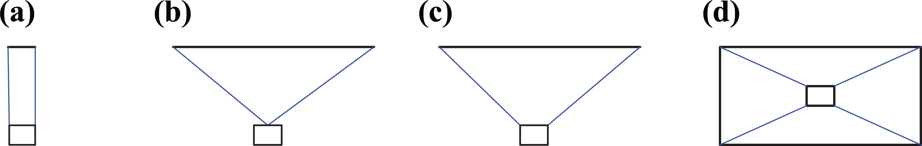
Configurations of planar CDPR: (a) Vertical parallel cables, (b) two-cable suspended, (c) two-cable underconstrained, and (d) four-cable overconstrained. CDPR: cable-driven parallel robot.
The kinematic diagram of the planar CDPR with four cables is shown in Figure 2. The base is determined by four cable connection points A1, A2, A3, and A4. The global coordinate system {A1 -XYZ} is established at point A1, the X-axis points from A1 to A2, and the Y-axis points from A1 to A4. A local coordinate system {P-xyz} is attached at the geometric center P of the end effector, which is defined by the cable connection points B1, B2, B3, and B4. The direction of {P-xyz} is parallel with the global coordinate system at the initial state.
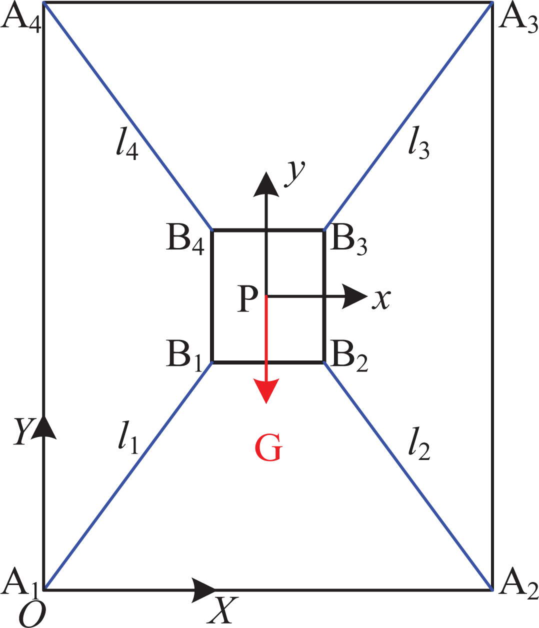
Kinematic diagram of the planar four-cable CDPR. CDPR: cable-driven parallel robot.
The rotation matrix

The length of the i’th cable can be obtained as

Differentiating both sides of equation (1) with respect to time, and one can obtain

Rewrite equation (3) in the matrix form, and the inverse kinematic model of the CDPR can be obtained as

where

The i’th cable force applied on the end effector at point B
i
can be expressed as ti

where

where
The solution of the cable force can be considered as a matrix solution problem, which is finding a vector

where
The structure matrix

where

Workspace analysis
As indicated by equation (10), the range of cable forces is an important factor that will affect the workspace of the CDPR. The minimum cable force is used to keep the cable in tension and its variation is limited. It is necessary to analyze the influence of the maximum cable force on the workspace. To describe the workspace quantitatively, the base is discretized with a fixed step and the number of discrete points that meet the equation (10) is taken to measure the workspace. For example, the width of the base is10 m, and the height is 20 m. The width of the end effector is 0.3 m and its height is 0.5 m. The base is discretized into 20301 points with the step of 0.1 m. The workspace coverage rate is calculated, which is the proportion of the number of discretized points that the geometric center of the end effector can reach to the total point number. In the analysis, the cable force is described by its ratio to the gravity of the end effector. The minimum cable force is 0.2 times of the gravity, and the maximum cable force changes from 3 to 50 times of the gravity. The workspace coverage rate of the CDPR under different maximum cable forces can be obtained, as shown in Figure 3.

Workspace coverage rate and boundaries with different maximum cable forces: (a) Workspace coverage rate and (b) workspace boundaries.
As shown in Figure 3, when the maximum cable force is small, its variation will affect the workspace significantly. With the increase of the maximum cable force, its impact sensitivity on the workspace decreases. The slope of the curve gradually approaches near 0 in Figure 3(a) if the maximum cable force is large enough. Excessive maximum cable force cannot effectively improve the workspace but put forward high requirements for the actuation system. Considering Figure 3(b) together, it is reasonable that the maximum cable force is about 10–20 times of gravity of the end effector. The maximum cable force is tentatively set as 10 times of gravity of the end effector.
The influences of the cable connection points of the end effector on the workspace are also analyzed. Considering the workspace for the exterior wall waiting for cleaning, the cable connection points of the end effector are symmetrically distributed, including four specific modes, namely noncross connection, horizontal-cross connection, vertical-cross connection, and double-cross connection, as shown in Figure 4. To represent different configurations through parameterization, a set of coordinates are defined. The horizontal x-axis reflects the coordinate difference between point B2 and point B1, while the vertical y-axis shows the coordinate difference between point B4 and point B1. Figure 4(e) shows the configurations of the CDPR under different conditions of the coordinates.

Connection mode between the base and the end effector: (a) Noncross, (b) horizontal cross, (c) vertical cross, (d) double cross, and (e) configurations of different coordinate areas.
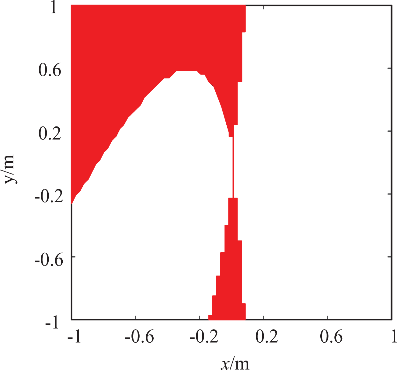
The atlas of workspace coverage rate varying with the cable connection points of the end effector can be obtained, as shown in Figure 5. Considering the factors of packing and transport, the cleaning module of the CDPR is designed as a rectangle with a side length no more than 1 m. Considering four connection modes of Figure 4, coordinate differences of the cable connection points vary from −1 m to 1 m, which are discretized by the step of 0.025 m. The workspace coverage rate can be calculated accordingly and illustrated in Figure 5. To keep the atlas simple and clear, white color is used to label the area, where the workspace coverage is less than 80%.
As can be seen from Figure 5, the distribution of connection points on the end effector has a significant impact on the workspace. When the noncross and double-cross connection modes are adopted and the width-to-height ratio of cable connection points on the end effector is similar to that of the base, the workspace decreases sharply. When the vertical coordinate difference of connection points is near 0 and the horizontal coordinate difference is large with the horizontal-cross connection mode, the workspace is larger, as illustrated at the left middle area of Figure 5. Similarly, when the horizontal difference of connection points is near 0 and the vertical difference is large with the vertical-cross connection mode, the workspace is also larger, as shown at the bottom middle area of Figure 5. Therefore, these two types of connection patterns of the end effector can be adopted to improve the workspace.

Workspace ratio changes with the connection points of the end effector.
As shown in Figure 3(b), four boundaries of the external wall are hard to cover for the CDPR. The upper and lower boundaries are easy to reach and convenient to be cleaned. However, the right and left boundaries are hard to be clean manually. It is required to make the workspace of the CDPR well cover the middle area of the building exterior wall. Considering the convenience of workers, upper and lower boundaries for 1.5 m could be left uncovered for the CDPR. Considering the width of the cleaning module, left and right boundaries can be covered and cleaned when the center of the end effector has a little distance to the edges. The offset distance is assumed to be 0.3 m. According to the cable connection points on the end effector, the workspace can be deduced to verify whether the workspace covers the middle area well. Results are shown in Figure 6. The red area in the atlas indicates feasible connection patterns of the end effector to make sure it can cover all the middle area of the base. The most feasible options locate at the upper left area, which is the horizontal-cross mode.
Cable connections that cover the middle area.
Stiffness analysis
Stiffness is used to measure the ability of a material or mechanical structure to resist elastic deformation subjected to external forces and torques. The larger the stiffness of the robot, the smaller the elastic deformation under the same external force and torque. When the generalized external force acting on the terminal

where
where

The material and specification of each cable are identical for the cleaning CDPR. Let k 0 be the unit stiffness of the cable, and one can obtain

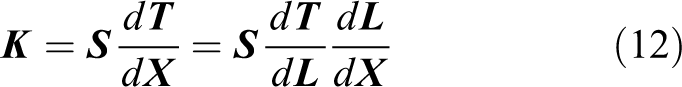
According to equations (12)
to (14) and the inverse velocity solution

Let

Since the CDPR has translational and rotational DOFs, units of the stiffness matrix are not unified. The rotational stiffness can be converted to the unified unit by multiplying the radius of the circumscribed circle of the cable connection points on the end effector. Then, the unified stiffness matrix can be expressed as

where
The stiffness of the robot can be evaluated with indices more clearly and concentratedly. The stiffness condition number index CR and the average stiffness index MR are adopted to evaluate the stiffness performance of the CDPR considering different cable connection points on the end effector. The definition of CR and MR is shown in equations (18) and (19), respectively, where


According to the definition of CR, its value is between 0 and 1. The larger the CR value, the better the stiffness isotropy. The average stiffness MR is the geometric average of the singular value of the stiffness matrix. Its value reflects the general stiffness of the CDPR at a pose. The larger the value, the better the stiffness. Since the stiffness condition number and average stiffness reflect the local performance, the global stiffness indices 31 can be obtained by averaging values of local indices in a certain area. To ensure the comparison consistency of the CDPR with different connection points on the end effector, the same area within the base is adopted, which is 1.5 m away from the upper and lower edges and 0.3 m away from the left and right edges. The global indices of GCR and GMR can be calculated by


where Nw is the number of discrete poses in the area. CR i and MR i , respectively, represent the stiffness condition number and average stiffness at the i’th discrete pose. The high-strength cable with a diameter of 7 mm is adopted and its stiffness is 125,000 N/m. The global stiffness condition number GCR and global average stiffness GMR in the target area are calculated according to equations (20) and (21), and the atlases are drawn considering different cable connection patterns, as shown in Figure 7.

Stiffness atlas with different cable connection patterns of the end effector: (a) Atlas of GCR and (b) atlas of GMR. GCR: global stiffness condition number; GMR: global average stiffness.
According to Figure 7, the stiffness of the CDPR is relatively low when the end effector is connected in the modes of noncross and double-cross, especially when the width-to-height ratio of the connection points on the end effector is similar to that of the base. The larger difference in the width-to-height ratio between the end effector and the base, the higher the stiffness condition number and the average stiffness. The horizontal-cross and vertical-cross connection modes are easy to obtain larger stiffness, as indicated with yellow color in the upper left and lower right corners.
Discussion on cable force range considering different bases
Considering Figures 5
to 7 together, the horizontal-cross connection mode is selected. The width of the end effector is 1 m and the height is 0.6 m. Although the configuration of the CDPR has been determined, the feasible range of cable forces needs to be confirmed considering different sizes of base determined by the building exterior wall. The procedure for determining the feasible range of cable forces is as follows: Determine the size of the base according to the wall to be cleaned, and the width and height of the base changes between 10 m and 30 m; Adopt the initial cable force range (0.2–10 G), T
max = 10G, and discretize the base by the step of 1 m; Use the method described in the second section to verify whether the target area (middle area) is all covered; If the answer is negative, then increase the maximum cable force T
max = T
max + 0.1 G, and return to step (3). If the answer is positive, one can find the maximum cable force T
max.
According to the above steps, the maximum cable force of the CDPR that can cover the target area of the various base is deduced as T max = 20 G.
With the deduced range of cable forces, the cable connection points of the end effector are reconfirmed under the condition of various base size. As shown in Figure 8, the red area illustrates the feasible connection patterns that cover the target area well. There are two feasible sections. The first one is in the left upper corner, indicating the horizontal-cross mode with a width of 1 m and height of 0.6 m. The other one is the section with the width close to zero. Considering the stiffness shown in Figure 7, the horizontal-cross mode is a better choice, which also verifies the cable connection points selected previously.

Cable connection analysis considering various base size.
Prototype design
With the deduced configuration and parameters, the prototype of the cleaning CDPR is designed. The cleaning CDPR is divided into three parts of winch modules, the cleaning module, and the control system, as shown in Figure 9. The winch modules include four cable winches and the electric wire and water pipe winch. The cable winch module is driven by the servo motor through a reducer. The winch is attached to the framework, which is reconfigurable. The counterweight is adopted to balance the cable force and avoid the overturn. The cable is wound on the single spiral drum, and the cable force is measured by the force sensor.

Prototype of the cable-driven cleaning robot and detailed design of winches. (a) Overview of the cleaning CDPR, (b) top cable winch, (c) bottom cable winch, (d) electric wire and water pipe winch, and (e) guiding device. CDPR: cable-driven parallel robot.
The electric wire and water pipe winch are used to provide electricity and water to the cleaning module on the end effector. Drums of electric wire and water pipe are driven by the common motor, which will control the lengths of wire and pipe according to the motion of the end effector. The slip ring is adopted to ensure a continuous supply of electrical energy and water with the rotation of drums. Large diameter nylon pulleys are used to guide the electric wire and water pipe, considering the requirement on the bending radius. Since the tension in the wire and pipe is small, the device to prevent the falling of wire and pipe is designed.
The cleaning module is mainly composed of a roller brush and two fans, as shown in Figure 10. A single-phase motor is used to drive the roller brush through the reducer. Two fans are used to keep the roller brush in contact with the wall during the cleaning and suppress the low-frequency vibration at the same time. The cable connection points can be flexibly adjusted to carry out further analysis on the reconfigurability.

Prototype of the cleaning module. (a) Front view and (b) back view.
The control system for the cleaning CDPR is shown in Figure 11. The main control unit is mainly composed of the Beckhoff CX6015 controller and an industrial computer. The computer is used for parameter setting and status display as the human interface. There are five distributed control units, which are located near the four cable winches as well as the electric wire and water pipe winch. The distributed control unit is composed of the servo driver and Beckhoff distributed ports. It controls the motor directly and feedbacks the cable force data. The optical fiber is used to connect the main controller unit and the distributed control units with long-distance communication capability.

Control system of the cleaning CDPR: (a) Main control unit, (b) Beckhoff CX6015 control card, and (c) distributed control unit. CDPR: cable-driven parallel robot.
Conclusion
To implement automatic and efficient exterior wall cleaning of high-rise buildings, this article analyzes and designs a planar CDPR with four cables. After the kinematic and static modeling, the influence of the cable force range on the workspace is analyzed, which reveals that increasing the maximum cable force will enlarge the workspace. However, the sensitivity of the workspace to the maximum cable fore will decrease gradually. The cable connection pattern of the end effector is analyzed considering the impact on the workspace, and the candidates of the cable connection pattern are determined. The stiffness analysis is carried out with the stiffness condition number and the average stiffness indices. Simulation results show that the larger difference of the width-to-height ratio between the end effector and the base, the higher stiffness of the CDPR. Considering practicality, the end effector is determined as 1 m wide and 0.6 m high, adopting the horizontal-cross mode of cable connection. Since the base of the CDPR varies with the building to be cleaned, the maximum cable force is confirmed with the specific parameters and is set as 20 times of gravity of the end effector.
With the deduced parameters, the prototype of the cleaning CDPR is proposed. The structure design of the winch modules is complete considering the reconfigurable framework and the counterweights of cable force. In the follow-up research, we will carry out the study on the stability of motion trajectory by reasonable vibration suppression and control methods.
Footnotes
Declaration of conflicting interests
The author(s) declared no potential conflicts of interest with respect to the research, authorship, and/or publication of this article.
Funding
The author(s) disclosed receipt of the following financial support for the research, authorship, and/or publication of this article: This research is jointly sponsored by the National Natural Science Foundation of China (No. U19A20101), National High-tech Ship Research Project of China (No. MC-201906-Z01), and National Key R&D Program of China (No. 2020YFB1710700).