
Abstract
This article presents the design of a hand exoskeleton that features its modularity and the possibility of integrating a force sensor in its frame. The modularity is achieved by dividing the exoskeleton in separate units, each one driving a finger or pair of them. These units or “finger modules” have a single degree of freedom and may be easily attached or removed from the robot frame and human fingers by snap-in fixations. As for the force sensing capability, the device relies on a novel force sensor that uses optical elements to amplify and measure small elastic deformations in the robot structure. This sensor can be fully integrated as a structural element of the finger module. The proposed technology has been validated in two experimental sessions. A first study was performed in a clinical environment in order to check whether the hand exoskeleton (without the integrated force sensor) can successfully move an impaired hand in a “Mirror Therapy” environment. A second study was carried with healthy subjects to check the technical feasibility of using the integrated force sensor as a human–machine interface.
Introduction
A wide diversity of robotic devices, which can actuate/assist the movements of the human hand, can be found in the current scientific literature. 1 Depending on the application, a hand exoskeleton may require uneven features. For example, a rehabilitation-aimed exoskeleton needs to be fairly backdrivable and allows a wide range of movement, so it is flexible enough to perform different rehabilitation exercises. 2 In contrast, an assistance exoskeleton must be stiff enough to ensure a firm grasping of objects present during activities of daily living and can sacrifice flexibility of movement in favor of predefined grasping patterns.
These different requirements result on diverse force transmission architectures:
Some devices use linkages in order to transmit the force from the actuator to the human joints.3–5 This is a stiff architecture that requires a proper alignment between kinematic centers of the linkage and human joints, but allows a good control of the hand pose. Due to the flexibility of the design, with the correct sizing, these mechanisms can achieve complex movement patterns with simple actuators.
Another extended architecture is the cable-driven glove.6–8 These are more flexible and simpler alternatives that rely on the own human joints to direct the movement, so they are less prone to uncomfortable poses. In contrast, they require pulleys to achieve high forces and are harder to control in intermediate positions. Additionally, this kind of exoskeletons need a pair of cables in antagonist configuration in order to assist both extension and flexion movements.
Finally, some devices use deformable actuators, like pneumatic muscles or shape-memory alloys, attached directly to the hand by means of a glove.9,10 They result in very light and simple devices, but actuators are not placed in the most advantageous place to achieve great forces.
Regarding the exoskeletons based on linkages, especially those which rely on electric actuators, having a measurement of the interaction force between user and device may result an interesting feature in order to ease control tasks and improve safety. In certain devices, different sensor technologies have been implemented, such as torque sensors, 11 strain gauges, 12 flexion sensors, 13 and miniature load cells. 14 These sensors may be effective in their respective applications but present some shortcomings for their integration in exoskeletons. In particular, torque sensors measure loads in the motor shaft so, in over-constrained mechanisms, they might not measure all the interaction forces. Strain gauges are complex to fix in the proper place and shorter ones may not perform correctly, so for being usable they require geometries with size comparable to human phalanxes. Another miniature sensors, like load cells or force-sensitive resistors, normally can measure force in only one sense (compression or extension) and those that can measure both directions are too big for the scale of the human hand.
Research background and objectives
In our previous paper, 15 we studied the feasibility of using multimodal systems in order to assist post-stroke patients during the execution of rehabilitation therapies with real objects. In this context, we evaluated the suitability of using a hand exoskeleton device, 16 such as the aforementioned ones, for assisting an impaired person during the grasping of objects present in activities of daily living. This device has experienced substantial improvements with respect to the previous design in order to be able to interact safely with disabled users.
In that previous experimentation, the electromyographic (EMG) signal of the forearm muscles was proposed as a method to estimate user’s intention and consequently trigger the open/close movement of the hand exoskeleton. This method proved to be effective, but it can be used only for users with a coherent and relatively strong EMG signal, which might not be the case for most patients. 17 From these results, there is a need for additional technologies that can detect the movement intention of the subject in order to cope with a wider range of user profiles.
Despite that the presented device will also be used in assistive context, the objective of the exposed research is to show whether the proposed improvements of the hand exoskeleton, including a miniature optical force sensor, allow its use in a real rehabilitation environment. Special attention will be given to the development of a force sensing method in order to measure the human–robot interaction forces and therefore to estimate user’s intention in rehabilitation scenarios.
Hardware description
Hand exoskeleton
Among the different existing architectures, we have decided to implement an exoskeleton based on the linkage approximation, since we consider that this is the most flexible solution in order to achieve a good compromise between the requirements of both rehabilitation and assistance scenarios. The motion transmission is based on a bar mechanism that allows the possibility of coupling the motion of phalanxes, so a natural hand movement is achievable using only one active degree of freedom per finger. Additionally, bars can transmit both tensile and compressive loads so the same mechanism is able to perform extension (most demanding movement in rehabilitation) and flexion (mandatory for assistance) movement of the fingers.
In detail, the designed exoskeleton is composed by three identical finger modules that drive index, middle and the pair formed by ring and little fingers. Each finger module has a single degree of freedom actively driven by a linear actuator. Unlike many of the referenced exoskeletons, due to the inherent uncertainty introduced by the human–exoskeleton interface (modeled as a slide along the phalanx longitudinal axis in Figure 1), we have decided not to rely on the human finger as the element that closes the kinematic chain. Conversely, we have adopted an approach similar to the one adopted by Ho et al. 5 This way, adding a pair of circular guides whose centers are coincident with the joints of a reference finger, the mechanism is kinematically determinate without needing the human finger. Ho’s device uses slots with flange bearings to implement the guides; this may result effective but requires precision machining and miniature elements to achieve a compact solution. In contrast, we have designed a double-edged guide that slides between four V-shaped bearings (Figure 2). These elements allow the optimization of the required space and may be easily manufactured by prototyping technologies or plastic molding. To make up for the additional constraints, we have decided to actuate only medial and proximal phalanxes.

Kinematics scheme of the finger linkage attached to the human finger. Metacarpophalangeal (MCP), proximal interphalangeal (PIP), and distal interphalangeal (DIP) joints have been modeled as revolute joints. Additionally, the interface between the module and the phalanxes has been modeled by means of slide.

Left: Finger module represented in its extreme positions. Right: Detailed view of the designed circular guide to minimize mechanical clearances with minimum friction.
As shown in Figure 1, the mechanism is formed by two parallel linkages that form two closed kinematic chains between them as well as with the human finger, resulting in a complex non-linear system of equations with multiple solutions. For this reason, kinematics has been solved by numerical methods.
18
Despite the nonlinearity of the equations, the relation between the stroke of the actuator


Since the movement of the linkage is fully determined and it has been sized for a reference finger dimension, we must design an exoskeleton-to-hand interface that can cope with misalignment and deviations from the reference finger. In this regard, we have designed a fixation system that uses ring-like pieces that are inserted on proximal and medial phalanxes and can be easily attached and released from the exoskeleton by a snap-in connection (Figure 3, left). This fixation system provides a fast and simple setup of the device, allows a fast reaction against possible dangerous situations, and provides more comfort to the user since it does not required to be tightened to the body (in contrast with straps or belts). Likewise, the finger module is fixed to the hand frame by means of a similar snap-in attachment; however, in this case, the finger module connection side has a slot that allows to adjust the position of the module along the longitudinal direction of the finger. The module is held in the correct place by the friction of the snap-in fixation (Figure 3, right). The hand frame consists on a semi-rigid commercial orthosis that wraps both palm and back of the hand.
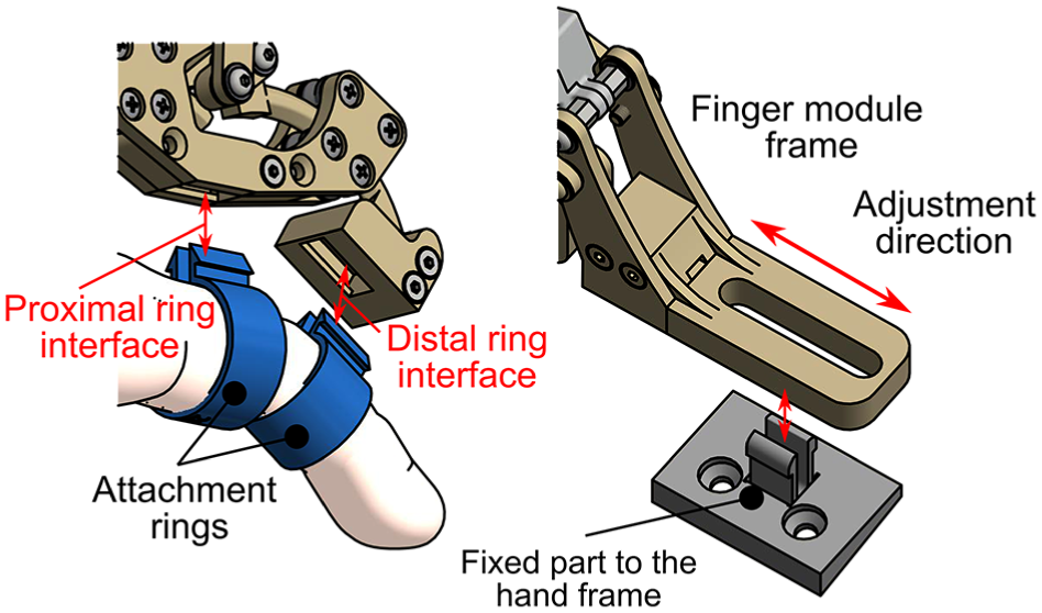
Left: Detailed view of the finger to exoskeleton snap-in fixing system. Right: Interface between finger module and hand frame.
Regarding the thumb, its movement cannot be well approximated by a planar mechanism, due to the opposition degree of freedom. However, many usual grasps can be performed by just holding firmly the position of the thumb. Therefore, in this design stage, we have designed a linkage that can be placed manually in a suitable pose and then be blocked during the activity.
In order to evaluate constructive factors such as clearances in the interfaces or joint misalignments, which cannot be easily considered in simulations, we have built a prototype to check the real performance of the proposed design (Figure 4). Each finger module has been manufactured by fused filament fabrication (FFF) three-dimensional printing with polylactic acid (PLA) as structural material. Additionally, we have printed a set of rings for finger diameters from 15 to 25 mm, with steps of 1 mm. The movement of the ring and little fingers is controlled with a single finger module by adding an intermediate part that couples their respective ring parts.

Top: Different parts that compose the hand exoskeleton; they can be easily assembled with the snap-in connections. Bottom: Fully assembled hand exoskeleton attached to a hand. This is the basic arrangement of the hand exoskeleton without any force sensing device.
Force sensing method
We propose the usage of optical sensors similar to the ones used in micrometry.19,20 These kinds of sensors work by measuring the deviation of a light beam incident on a photosensitive surface. In particular, we have designed an optical setup composed by:
A light emitting diode (LED) as a point light source.
A pinhole element that will narrow the light emission bulb of the LED, so stray light is minimized.
A cylindrical lens that refract the beam of light that comes from the pinhole and focus it in the opposite side.
A photodiode array that gathers the light focused by the lens, outputting current signals proportional to the light that hits each individual photodiode.
The deviation of the light beam is induced by displacing the cylindrical lens along the direction perpendicular to both optical and lens axes (Figure 5). With a correct sizing of the optical elements and gaps between them, it is possible to convert the displacement of the lens to deviations of the incidence of the light in the photodiode array with one order of magnitude higher (e.g. tenth of millimeters to millimeters). Placing the photosensitive surface out of focus with respect to the lens, we can obtain a luminance distribution along the photodiode cells. This distribution will vary with the deviation of the lens, so certain photodiodes will experiment a loss of luminance while the remaining ones will receive the rest of the light. Figure 6 shows the light distribution in the photodiode array computed by ray-tracing for the next hardware configuration:
Light source: LED Kingbright APTD1608LSECK/J3-PF.
Pinhole: 0.8 mm diameter hole in a wall of 5 mm width.
Lens: poly(methyl methacrylate) (PMMA) rod with a diameter of 2 mm, refraction index: 1.49.
Photodiode array: OPR5911 Quad Photodiode, grouped into two pairs
Light source–lens distance: 6.5 mm.
Lens–photodiode distance: 3.5 mm.
Sensor total length: 10 mm.

Schematic view of the optical force sensor. Blue lens and rays correspond with the neutral position. Red lens and rays show how do a small displacement in the lens changes the light distribution in the photodiode array (Ph1 and Ph2).

Relation between the fraction of total light received by each pair of photodiodes (Ph1 and Ph2) and the lens displacement.
The proposed implementation achieves an unbalance of about 60% of the input light between both pairs of diodes in a displacement range of ±0.1 mm. Moreover, the amount of light received by each cell with respect to the lens displacement clearly follows a linear trend. Therefore, due to the linearity of the photodiode array response, we may expect that the response of the proposed sensor is consequently linear.
In order to convert the displacement measurements into force values, the lens is connected to the frame of the sensor by means of an elastic interface such that its shift is proportional to the force through Hooke’s law. Due to the small movements required to produce a significant output, the stiffness of the interface may be such that the deformation is not appreciable by the user nor affects the exoskeleton kinematics.
With the proposed configuration, the elastic interface has a theoretical stiffness of 125 N/mm, if the extreme admissible lens displacement is ±0.1 mm, then the limit force that can be measured with this implementation is ±12.5 N. Regarding the sensor resolution, due to the basic electronic components and techniques used for the signal acquisition (general-purpose operational amplifiers LM324 and analogical to digital converters integrated in an ATmega328P microcontroller, with a simple mean filter with five-element window), the electronic noise limits the smallest measurable step to about 0.05 N. These are preliminary values based on theoretical assumptions; however, further studies will be carried out in order to accurately determine and improve the performance of the sensor.
Sensor integration
The main feature of this sensor is its potential miniaturization, so it can be inserted between the human interface and the force transmission elements. One of the most advantageous locations to install a force sensor is the distal ring interface, since the leverage is maximum in this position. For this purpose, the original distal link of the finger module has been split into two elements (Figure 7, bottom): the block formed by the ring housing and the electronic components (colored in green and gray), and the circular guide attached to the rest of the linkage (colored in blue). Both parts are bound by a plate that works like an elastic interface (colored in yellow).

Top: Comparison between the original distal link of the finger module and the replacement link with integrated force sensor. Bottom: Section of the modified distal link that shows the implementation of the sensor proposed in Figure 5.
Top of Figure 7 shows the comparison between the original and modified distal links. The addition of the force sensor does not entail a remarkable increment in the size of the part, and the travel of the guide remains unaltered, so both configurations can be freely exchangeable without affecting the rest of the exoskeleton.
Unlike other technologies that measure the force directly in the actuator, the proposed architecture can isolate the interaction force between the user and devices, neglecting other effects like internal reactions and frictions in the linkage. It also avoids the measurement of preloads and uncertainties present in sensors that must be in contact with the human skin, like button load cells or force sensing resistor (FSR).
Experimental validation
For the validation of the exposed system, two different experiments have been defined. In the first experiment, the hand exoskeleton has been tested with six post-stroke patients to evaluate the improvements of the new mechanical design with patients. These tests will evaluate the performance of the hand exoskeleton (previous to the setup of the force sensor) when it is attached to a paretic hand.
On the other hand, an experiment with eight healthy people has been carried out to test the performance of the novel force sensor presented in this work. In these tests, two different control strategies that use the force feedback will be studied.
Validation of the exoskeleton
In order to test and validate the new design of the hand exoskeleton, an experiment based on Mirror Therapy (MT) concept has been carried out. Since MT has been widely used with satisfactory results in upper limb rehabilitation,21–24 the design and development of a task based on this therapy with the exoskeleton seems to be appropriated to improve and validate the hand rehabilitation system. The proposed activity involves the next systems:
5DT Data Glove, from Fifth Dimension Technologies, to measure the position of the fingers of the non-paretic hand.
Hand exoskeleton attached to the paretic hand in order to perform movements following the data extracted from the 5DT Data Glove.
Virtual Reality (VR)-based task, developed with Ogre3D, as a user interface where two hands are shown so that the user can see a visual feedback of the movement of his hands.
The objective of the task is to reach the target pose of both hands that is shown in the VR. To this end, subjects have to move their non-paretic hand, and the hand exoskeleton will move their paretic hand following the same movement. Based on the movement of the non-paretic hand, a target trajectory is used to control the exoskeleton by means of a PID controller with the exoskeleton position feedback (Figure 8). For simplicity, this target trajectory is the same for all actuated fingers. In Figure 9, the setup for the experiment is shown.
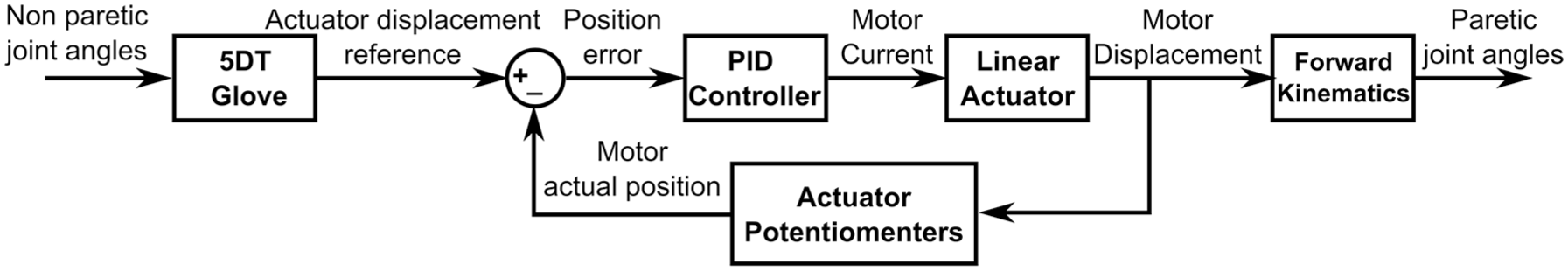
Control scheme of the position control commanded by the 5DT Glove used for the validation of the exoskeleton with Mirror Therapy.
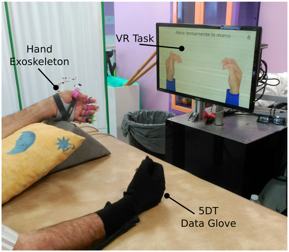
Setup for the Mirror Therapy based task: (1) 5DT Data Glove on the right hand, (2) hand exoskeleton on the left hand, and (3) Virtual Reality (VR)-based task.
The study has been performed in a hospital of attention to chronic patients and long-stay. The experiment protocol of the proposal study was approved by the Medical Ethics Committee. The medical team has been responsible for including patients who are receiving physiotherapy and occupational therapy treatment. All patients have been informed properly by the medical staff and they gave written consent before starting the study, indicating that they understood the purpose and requirements of the study. A total of six patients (Table 1) were involved in this study. Each patient was asked to carry out about 8–15 movements in several sessions (depending on the patients’ will). All of them were able to perform the task with no major problems.
Demographic and clinical characteristics of participants.
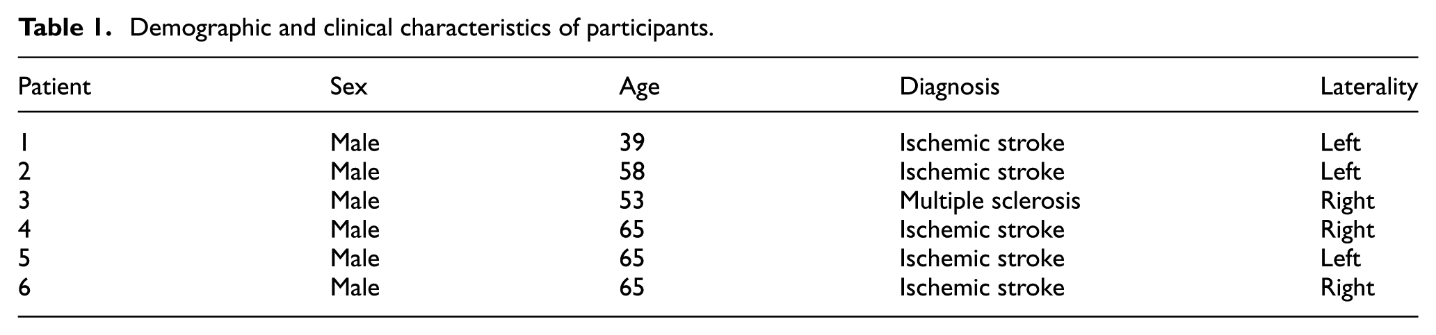
Table 2 displays the statistics for the position error of the finger modules in terms of joint angles for each user. These data show that there are three different working conditions in which the performance of the system is clearly different (Figure 10). When holding a position (steady position), the mechanism has an accuracy of typically less than 0.2°, with a root of mean square error (RMSE) lower than 0.4°. When following the trajectory computed by the glove in the non-paretic hand, the position error shows two different distributions that depend on the rate at which the reference changes. This is due to the speed limitation (7.5 mm/s) empirically imposed on the displacement of the linear actuator, in order to avoid abrupt movements in the impaired hand that might be counterproductive for the rehabilitation, as well as to prevent reaching the limit speed of the actuator. Thus, when the reference changes at a rate lower than the limit speed (suitable speed), the errors are typically lower than 1.5°, with a RMSE less than 2.5°. However, if users move their reference hand at a rate higher than 7.5 mm/s (fast reference), then the speed of the actuators is limited to that value and the tracking error increases with the speed. These phenomena are shown in the example presented in Figure 11.
Results for the “Mirror Therapy” experiment.

PIP: proximal interphalangeal; MCP: metacarpophalangeal; RMSE: root of mean square error.
Data refer to the statistical analysis of the error in position of the finger modules for all trials of each user. Data have been split into three cases according to the variation rate of the reference signal (
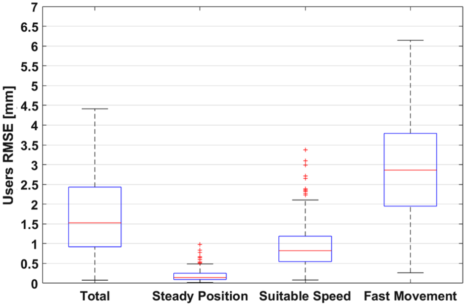
RMSE of the trajectories of all users in terms of motor stroke. There are three differentiate distributions for the error according to the variation rate of the reference signal. Red line indicates the mean value, blue boxes enclose the samples between percentiles 25 and 75, and black whiskers cover an standard deviation of

Reference and actual motor position for a single finger. Sample extracted from a session of the user 4. This example clearly shows the difference between the tracking error when users move their non-paretic hand at different speeds. The first part of the opening–closing cycle is performed at a suitable speed with a low tracking error. The second part of the movement is carried out at an excessive speed and the tracking error increases due to the limitation on the speed of the hand exoskeleton.
Ideally, during this kind of therapy, both hands should move at once (suitable speed or steady position cases). Since the reference signal is only controlled by the subject through the 5DT Data Glove, users may move faster than the maximum allowed speed. However, with practice and familiarization with the therapy, they can achieve a sufficient control over the system.
One point that must be underlined is that the joint errors quantified in this section are computed by applying equations (1) and (2) to the displacement of the actuators, so real errors will depend on mechanical clearances and hand bio-mechanics. A more detailed study can be found in a previous work. 18
Force sensor preliminary tests
Based on force measurement provided by the developed optical force sensor, we have defined two control strategies to command the hand exoskeleton. By being able to measure the force interaction between the robotic device and the user, we are able to estimate the user’s movement intention. According to this, we have implemented two control strategies:
The first strategy has been named “Triggered Control.” This method consists in measuring the intention of the user when he or she is trying to perform a certain movement. When the measured force exceeds a certain threshold value, previously calibrated, the exoskeleton will start the full movement autonomously (fully open or close the hand). This strategy has been implemented using the state machine shown in top of Figure 12.
The second strategy has been named “Continuous Control.” In this mode, the force information, based on the interaction of the robot with the user, is used as feedback in the control loop in order to move the hand exoskeleton in the desired direction. In this way, users can freely move their hand to reach a target pose. Bottom of Figure 12 shows the block scheme of the implemented control, which consists in a proportional closed-loop controller with a negative gain and null force as reference signal.

Control schemes for both studied control strategies. Top: State machine for implement the control by means of a force trigger. Bottom: Block diagram that shows a zero force control.
We have carried out an experimental session with healthy subjects (Figure 13) to test and validate both force-based control strategies. For this purpose, we have established the following protocol:
First, subjects were informed of the objective and procedure of the experiment.
An adaptation period of few minutes is given to the subjects to practice both modes of control (Triggered and Continuous Control) before starting the experiment.
Then the subject performs the Triggered Control. Each subject tries to perform 20 movements (10 opening movements and 10 closing movements). Using a graphical interface, they have to show their intention to perform the ordered movement within 5 s.
Finally, the subject performs the movements using the Continuous Control approach. Each user has to perform four movements. In every trial, they have to reach a specified target within 5 s to achieve a successful movement. Target position ranges from 10 metacarpophalangeal (MCP) degrees to 40 MCP degrees (and its associated proximal interphalangeal (PIP) angle) with steps of 10° between trials.

Setup for the force-based control experiment. A detail of the integrated force sensor is shown in the upper right corner.
Eight subjects participated in the experiment. All were healthy, with no major cognitive or physical deficits. They were aged between 26 and 44, mean age 31.6 years, median age 27 years, and standard deviation 8 years. Before the study began, ethical approval was obtained from the Ethics Committee of the Universidad Miguel Hernández of Elche, Spain.
Table 3 summarizes the users’ profile and the results of the experimentation with “Triggered Control” for each one. As for the parameters used to evaluate the performance of the system, response time parameter is computed as the mean time required to trigger the movement of the exoskeleton since visual stimuli were given; false positives correspond to movements triggered before the user is told to initiate the movement; and fails indicate the trials in which movement was not triggered after 5 s since the visual signal.
Results for the “Triggered Control” experiment.

Table 4 presents the results of the tests performed with the second strategy “Continuous Control” for the same subjects. For each user and trial, the absolute value of the steady-state error is shown in terms of joint angles.
Results for the “Continuous Control” experiment.

MCP: metacarpophalangeal; PIP: proximal interphalangeal.
Regarding the “Triggered Control” tests, the system presents a success rate between 95% and 100%, with only two fails or false positives in 160 trials. This fact indicates the simplicity of use of the system for this control strategy. The disparity in response time for the different users is due to the the reaction time to the visual stimuli inherent to the user, and not to the reaction time of the system, since fastest users can achieve response times lower than half a second.
As for the “Continuous Control” tests, the error in reaching a certain target varies significantly between users, since subject 7 can command the exoskeleton with a mean MCP accuracy of 0.23° while subject 3 reaches the target with an error of 2.17°. However, as shown in Figure 14, when comparing the error between movements, there are no significant differences between the error distributions corresponding to the different targets. Therefore, one can conclude that despite that the skill of the user is a decisive factor for the performance of the system, the target position does not affect the precision of the positioning.

Statistics of steady-state error in “Continuous Control” for all users according to the target position.
Furthermore, we must stand out that the chosen population included a wide range of hand sizes, requiring the usage of most of the different ring sizes. Results show that there is no relation between these sizes and the performance in the tests, so we can conclude that the exoskeleton is relatively robust to deviations respect to the reference design hand size.
Conclusion and future work
After considering the results obtained in the experimental sessions, we can conclude that the designed device is fit for exhaustive tests with patients with hand physical impairments. Thanks to the newly developed force sensor, the exoskeleton now provides a suitable interface that can cover several rehabilitation stages. In early stages when the patient cannot perform any kind of movement in the affected hand, the proposed MT-based robotic therapy can be an effective starting point. Once the users get certain hand control, they might use “Triggered Control” mode to actively involve the paretic limb in the exercises. In advanced stages of the rehabilitation process, a continuous force feedback control strategy may result an interesting approach to gain fine motor control and grip strength.
All the presented tests were performed with the same finger modules without requiring any kind of repair or maintenance between users. This is a first sign that the usage of technical polymers as structural material might be feasible. This fact might lead to a lightweight device and a design that can be cheaply mass produced with molding techniques. Anyway, this is only a preliminary conclusion that needs a more detailed research. With the loads estimated with the newly integrated force sensor, finite element structural simulations can be performed with different polymers so the most suitable structural material can be chosen. The knowledge of the resistance limits of the different structural elements, in conjunction with the force measurement, might allow the implementation of additional security measures to preserve the integrity of the device and the user.
Footnotes
Handling Editor: Francesco Aggogeri
Declaration of conflicting interests
The author(s) declared no potential conflicts of interest with respect to the research, authorship, and/or publication of this article.
Funding
The author(s) disclosed receipt of the following financial support for the research, authorship, and/or publication of this article: This work has been founded by the European Commission through the project AIDE: Adaptive Multimodal Interfaces to Assist Disabled People in Daily Activities (grant agreement no: 645322), by the Spanish Ministerio de Economía y Competitividad through the project DPI2015-70415-C2-2-R, and by Conselleria d’Educació, Cultura i Esport of Generalitat Valenciana through the grants ACIF2016/216 and APOTIP 2016/021.