
Abstract
In order to precisely measure water impact loads of a spherical structure vertically dropping onto a calm water surface, a new validity check of the analysis using the levitation mass method experiment is proposed. The main feature of levitation mass method experiment is to obtain a better estimation of early water impact loads through the application of Doppler effect. Experimental results of different heights are verified based on the Assessment Index and are in comparison with the classical experimental data for validation purpose. It shows that the levitation mass method measurement is useful and effective to obtain the water impact loads for the crashworthiness analysis. Besides, early water impact hydrodynamic behaviors are simulated based on the nonlinear explicit finite element method, together with application of a multi-material arbitrary Lagrangian–Eulerian solver. A penalty coupling algorithm is utilized to realize fluid–structure interaction between the spherical body and fluids. Convergence studies are performed to construct the proper finite element model by the comparison with experimental results, where mesh sensitivity, contact stiffness, and time-step size parametric studies are thoroughly investigated. The comparisons between experimental and numerical results show good consistency by the prediction of the water impact coefficients on the structure.
Keywords
Introduction
Recently, some analytical, experimental, and finite element methods have been available to water impact domain, such as naval and offshore structures slamming, aircraft ditching, space capsule water landing, and torpedo water entry.1,2 A quintessential example of aircraft ditching is on the 15 January 2009, the pilot of an Airbus A320 performed an emergency landing onto the Hudson River successfully rewriting aviation history. The lost Malaysia Airlines Boeing 777 (Flight MH370), on 26 March, 2014, was conjectured to be ditched on the south Indian Ocean. And the Airbus 320-200 of AirAsia Flight QZ8501 had not controlled ditching into seawater on 28 December 2014. More and more researchers pay attention on water impact problem, especially for aircraft ditching, in the view of structural crashworthiness design and other related factors, for example, water flow and water jet.
Water impact is a complex physical phenomenon which is different from ground impact. Water impact is a soft impact scenario which involves fluid–structure interaction (FSI) behavior resulting in more severe crash. It is frequently analyzed by a combination of analytical methods, experiments, or numerical simulation.
T Von Karman 3 and H Wagner 4 were the pioneers to consider theoretically study water impact problem for the purpose of estimating the impact forces and pressures based on the conservation of momentum. The rigid body impact against a calm fluid surface is analyzed with the theory of potential flow neglecting gravity. Water pile-up and jet are important factors distinguishing von Karman’s and Wagner’s works. Following their works, more accurate results were obtained with closed-form solution, experiment, and numerical methods.
Miloh 5 solved the displacement, velocity, and acceleration histories of a rigid sphere analytically, by employing the matched asymptotic method. The semi-Wagner approach to determine the slamming coefficient is in the consideration of water splash up which make significant effect on the impact force. Generalized Wagner model (GWM) was created using the linearization analysis on the exact boundary condition around the intersection between the body and the free surface6,7 and can thus obtain satisfactory results. Modified Logvinovich model (MLM) was proposed by Korobkin and Pukhnachov 8 and the hydrodynamic loads were computed by taking into account nonlinear effects related to the quadratic term of the Bernoulli equation and the real geometry of the wetted surface. Most of the analytical studies on the water impact problem were limited by some hypothesis because water impact problem is a complex event, so experiments were widely performed.
Historically, many experiments were carried out in laboratory to study the impact loads on a body entering a smooth or rough liquid surface. The first study used photography to illuminate the dynamics of fluid flow following spherical body entry. Further significant experiments with spheres entering free surfaces of water were conducted to collect more hydrodynamic loads with pressure sensors or piezoelectric accelerometers.9–11 To determining water impact forces by measuring acceleration, the accuracy of data for a given experiment is always limited by the measuring devices or experimental environment. So it is indispensable to utilize a reliable and verified numerical method, which finally becomes a part of the methodologies to analyze structure crashworthiness during water impact.
In recent decades, many numerical methods such as the grid-based 12 and mesh-free methods 13 have been widely implemented, partly accompanying experimental tests to study water impact problem.14–16 Numerical simulation saves both time and computational effort, is able to deal with complex structures, and provides valuable insight. But it is particularly difficult to validate the numerical models because of the lack of most precise and accurate experimental data.
The present work consists of two parts: water drop experiment and numerical simulation. First, the water impact experiment using the levitation mass method (LMM) is presented and is assessed to accurately measure the water impact loads of a three-dimensional rigid spherical body dropping onto a water surface. This is then compared with analytical results and some classical experimental data. The ultimate intention of water drop experiments is to generate reliable data for numerical validation. Second, numerical simulations by the arbitrary Lagrangian–Eulerian (ALE) method are performed on the explicit FE code LS-DYNA. Convergence study is carried out by sensitivity analysis which focuses on some important numerical parameters, that is, the mesh density of the fluid in the impact domain, contact stiffness, and time-step. Numerical modeling techniques thus validated can be used to simulate the water landing of other sphere-bottomed structures. The comparisons between two parts show good consistency by the prediction of the water impact coefficients on the structure. The recent work will draw some guidelines of the improvement for further investigations for water landing problems.
Mathematical formulations
The origin of Cartesian coordinate system OXYZ is set on the impact point of the fluid surface at time


where

Sketch of the water impact problem.
The body boundary conditions require no flow through the body surface, so


In finite element analysis, the governing equations of mass, momentum, and energy based on ALE description are described respectively as follows


The relation of Lagrangian, Eulerian, and referential coordinate can be expressed as

where
The body is treated by a Lagrangian formulation and the fluid by multi-material ALE formulation. The multi-material arbitrary Lagrangian–Eulerian (MMALE) formulation is a finite element method for modeling the fluid with the capability to deal with large deformations in fast dynamic problems like water impact or slamming. Some equations of state dependent on the problem type are also needed for the solution of the system. The coupling loads at the fluid–structure interface are computed by a FSI solver. The main solution methodology utilizes explicit time integration to save a great deal of processing time without inverting the stiffness matrix at each time-step. The coupling algorithm uses a penalty coupling similar to penalty contact in Lagrangian analysis. 17 The former is more suitable for solving FSI problems.
The multi-material ALE formulation is adopted by overlap capability of grid to structure in the numerical analysis for water impact. The MMALE description is based on the interface reconstruction and advection algorithm. The interface reconstruction implies the capturing interface between two or more materials and the free surface is captured by the volume-of-fluid (VOF) method. The ALE configuration is due to the motion of the material of the initial material configuration in the interface tracking phase. When the mesh moves with one or multi-material in the pure Lagrangian approach with easily tracking moving interfaces and boundary conditions, the mesh remains fixed in the pure Eulerian description. The advection algorithm is used to approximate the variables like density, the stress tensor, internal energy, and history variables. It will not change the mass, momentum, and energy of the system. In the ALE formulation, it allows two materials in one element in a fixed mesh and contains a certain volume fraction of each material. When the nodal repositioned has been performed, the solution from the previous configuration need to be mapped onto the new one, known as the advection step. The advection algorithm is presented in the remap step. The interface cut with a plane between these two materials is to be tracked by an advection algorithm. In LS-DYNA, there are two different algorithms, i.e. the Donor Cell algorithm and the Monotone Upwind Schemes for Conservation Laws (MUSCL) Van Leer scheme. 18 MUSCL Van Leer scheme can achieve second-order accurate monotonic results and will similarly keep the mass and energy conservation and it is particularly important to avoid the negative values.
Assessment Index
The analytical models with some assumptions provide simple hydrodynamic results for engineering applications, especially for preliminary design. The structural body can be generally assumed rigid in the hydrodynamic loads assessments of the theoretical analysis. And gravity and buoyancy effects can be neglected in comparison with the impact forces. The airflow is usually unimportant, and irrotational flow of incompressible water can be assumed. And the free fluid surface is assumed to be an equipotential surface which pressure is the initial atmosphere pressure or zero.
It is commonly convenient to assess the results in terms of some dimensionless parameters. 6 The impact drag coefficient is representatively designated to the assessment index. It governs that the impact forces of a body impacting onto water are mathematically defined as

where
The water impact drag coefficient also is given base on the generalized von Karman model (GvKM) with precondition of the small-time penetration. If the added mass is approximated by the Lamb-disk model, then at free dropping situation, the drag coefficient is expressed as

where mass coefficient is
In the present work, the GWM and the GvKM are applied to determine the upper and lower threshold of water impact load in order to carry out further assessments of the water drop experiments.
Experiment apparatus and measurement
The impact of a stainless sphere on the clam water surface with initial downward velocity with variable water-entry height and then plunging into the water is tested by the LMM measurement based on the Doppler effect.19,20 The experimental setup (shown in Figure 2) divides into four systems, including water pool, the laser Doppler measurement module, quick-releasing facility, and high-speed camera.
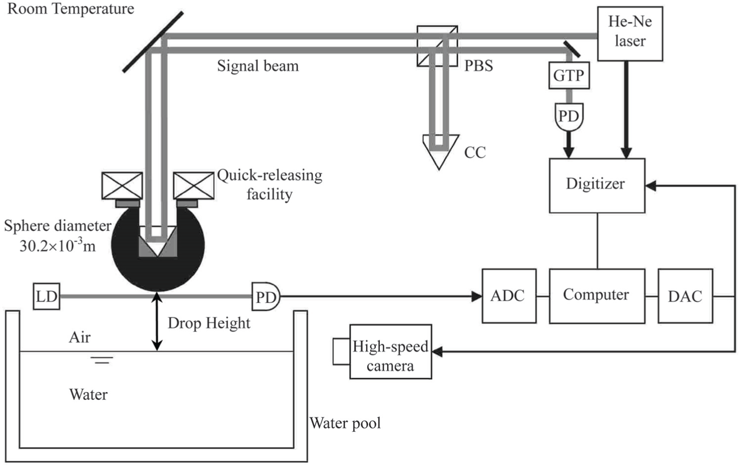
Experimental setup arrangement.
Water pool is made of transparent acryl resin. During the test, it allows to adjust the variable dropping height which is between the bottom of the test article and water surface. The quick-releasing facility is equipped with a hollow-circular electromagnet to guarantee the test articles quick-release automatically without any vibration. In this experiment, the test article is a tempered stainless sphere, which is punched a hole on the top and inlaid a cube corner prism. A high-speed camera is used to capture the images around the impact region with a resolution of 135,424 pixels and a frame rate of 15,000 fps. The digitizer and the high-speed camera are initiated by a sharp trigger signal generated using a digital-to-analog converter (DAC). This signal is activated by means of a light switch, which is a combination of a laser diode and a photodiode.
The laser Doppler measurement module utilizes the laser Doppler interferometer to measure the velocity. A digitizer records the output signals of PD1 and PD2 with a sample number of 5M for each channel, a sampling rate of 30M samples per second, and a resolution of 8 bit. A Zeeman-type two-wavelength He-Ne laser is used as the light source. Each beam has different frequency and orthogonal polarization.
A method to measure the water impact loads has been proposed by modifying the LMM 21 to avoid aliasing and guarantee a reasonable large number of sample points during the initial phase of the impact. Differentiating the body’s velocity which is calculated from the measured value of the Doppler shift frequency of the signal beam of the interferometer, the acceleration is calculated. The acquired water impacting accelerations are made to nondimensional impact drag coefficient as the assessment index.
Three sets of test-run are conducted by the difference of the predetermined dropping position from the water surface. In an effort to guarantee the reliability of measures and accuracy of test data, five drop measurements are taken in each set of measurements. The dropping heights are about 136, 150, and 190 mm, respectively. Figure 3 presents the assessment index against the nondimensional penetration depth with the dropping height of 136 mm, together with the available literature-based experimental results for the comparative verification. In order to compare with each other, the previous experimental data are introduced from the classical experimental methods. A variety of sensors are mounted on the specimen to measure impact decelerations and pressures, for example, piezoelectric accelerometers and pressure transducers. Or a high-speed camera is used to capture pictures to provide insight of it.

Nondimensional impact drag coefficient of a rigid sphere as a function of the nondimensional penetration depth, comparison of Doppler measurement results with three conventional experimental ones.
The data curve change shows that the new measure for the dropping sphere coincides well with the other experimental data. It shows the impact drag coefficient rises rapidly to a maximum when the depth of penetration is less than a fifth of the radius in the early entry stage. Thereafter, it declines more gradually when water-entry cavity begins to obviously emerge. The maximum of the drag coefficients of these data curves are very good consistency only with very small deviation, as shown in Figure 4.
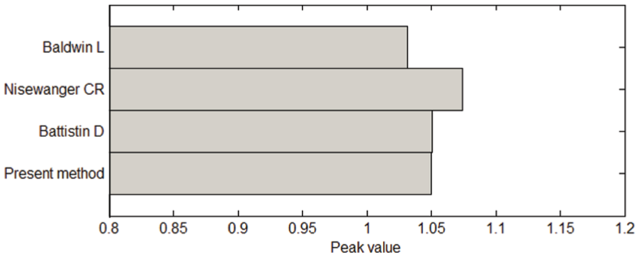
Accuracies of the peak value.
LMM experimental results were further compared with the maximum and minimum impact load from GvKM by equation (12) and GWM 7 solution, respectively, in Figure 5. The thresholds of two analytical solutions are used to limit the peak loads for engineering application. Three sets of experimental results validated the new LMM measurement for the peak loads. The nearly identical curves indicate a good repeatability of the measurements. Comparing the present measures to the other classical experimental methods, the repeatability and the reliability of the tests of impact accelerations supports the effectiveness of the crashworthiness design for the sphere-bottom structures.

Dependence of nondimensional drag coefficient with different dropping heights.
Numerical modeling and analysis
The experimental cases are numerically simulated using the ALE method and a penalty algorithm. The main interest of the numerical simulations has been compared with the Doppler measure to estimate the efficiency of the nonlinear explicit codes to predict dynamic response of the structure. Discrete structural geometry and material properties are important to gain accurate simulation results. It is very convenient to model with separate meshes for FSI between ALE (fluids including air and water) and Lagrangian (impactor structure) materials. The fluid is defined as the MMALE which is most versatile and widely used 1-point ALE multi-material element, the structure is modeled with the classical Lagrangian approach by the default Belytschko–Tsay element formulation. The MMALE solver in the finite element analysis codes LS-DYNA is available to solve the mathematical formulations for water impact problem.
Material modeling
Structure models
Structure modeling is based on the assumptions of no deformation and rotation motion, and the default Belytschko–Lin–Tsay shell element and the material type called *MAT_RIGID. These are utilized to improve the computational efficiency. The shell element formulation, integration rule, and cross sectional properties are defined with the LS-DYNA card *SECTION_SHELL. We use two integration points through thickness, element formulation 1, and shear factor 5/6 in all the analyses.
In order to reduce the computer time-consumption, a quarter of the models is only established with symmetric boundaries on XOY and YOZ planes, as shown in Figure 6. A cylindrical hole is embedded into the spherical body in order to insert a cube corner prism. Meanwhile, it demands the optical center coincide with the center of gravity of the sphere.

Three views of water impact model and 1/4 ALE model with gradient mesh.
In all case studies, the properties of the spherical body are taken as below. The total mass of the entire spherical body is approximately 93.88 g. The density of the stainless steel body is 7650 kg/m3, Young’s modulus is 2.0 × 10¹¹ N/m2, and Poisson’s ratio is 0.3. Poisson’s ratio and Young’s modulus of the material do not change the behavior of the sphere part for its rigidity.
Fluid models
A set of constitutive equations that realistically describe the physics of material needs to be numerically solved with appropriate boundary conditions. The constitutive model and the equation of state (EOS) model are simultaneously utilized to describe the nonlinear properties of a fluid or fluid-like deformation material in explicit dynamic codes LS-DYNA. The constitutive model describes the partial stress of the material, and the EOS for the relationship between the volume of deformation and stress. So the total stress tensor is often partitioned into deviatoric stresses and pressure component, that is

where
To begin with, the air is modeled as perfect gas with zero shear strength. Material model *MAT_NULL and EOS model *EOS_LINEAR_POLYNOMIAL were contemporary used here. The pressure is given by

where
And then, the water was modeled using the Mie–Grüneisen EOS based on a cubic shock velocity–particle velocity. Actually, the linear polynomial EOS for air property is Mie–Grüneisen type. EOS defines the pressure, using the relative volume as

where

where
Material properties of water are very important in water impact simulation, so a suitable set of fluid properties were validated through several of cases analysis. All fluid materials parameters and constants together with their values as specified in SI units are summarized in Table 1.
EOS coefficients of fluid models. 22

Actually, fluid domain is infinite or similar infinite domain in water impact problem. The limitation of fluid domain should be defined in order to avoid the boundary effect at the
where
In order to decrease the computation domain and obtain simultaneously a convergence of the results, the infinite models of fluid can be considered as the finite one shown in Figure 6. The fluid domain is limited to L1 × L1 × (H1 + H2): 32 mm × 32 mm × 30 mm (length × width × height) as plotted in Figure 6 (left). But in water drop tests, the impact waves of pressure will go through the fluid domain and reflect back to influence the impacting body and interact with the fluid, resulting in some high-frequency numerical noise. Besides, in the numerical analysis, a non-reflecting condition is used to all around closed boundaries directly for reducing the reflection of shock wave emerging from fluid–structure impact.
Parameters selection
Considering the numerical stability, the penalty-based coupling and viscous hourglass control must be discussed here as given below.
Penalty-based coupling
The penalty-based coupling treats the FSI problem between a Lagrangian formulation modeling the structure and an ALE formulation modeling the fluid. It allows fluid to flow around the contact surface of a Lagrangian structure but not penetrate the contact surface. And at the same time, the ALE algorithm will search for the elements which intersected or overlapped between the Lagrangian parts and the ALE multi-material groups. Then it computes the penetration distance of the Lagrangian surface across the ALE material surface during a remap step. The penalty coupling behaves like a spring-damping system and the magnitude of this penalty forces is calculated proportional to the penetration and spring stiffness

where
The coupling mechanism between the MMALE and the structure is controlled by the keyword *CONSTRAINED_LAGRANGE_IN_SOLID (CLIS). The keyword is used to define contact between MMALE groups (*CONTROL_ALE) and Lagrangian elements. The parameters including penalty factor are listed in Table 2.
Selected parameters for the *CLIS card.

Viscosity hourglass
For the present numerical method, it is necessary to introduce artificial viscosity to deal with the shock wave intermittent problem. In order to let the numerical results consistent with experimental data, the effective way is to regulate a first-order and second-order artificial viscosity coefficient in *CONTROL_BULK_VISCOSITY card. 23 The bulk viscosity may create an additional additive pressure term given by

where
Because excessively large deformations occur in flow jet, resulting in numerical problems, a reduced hourglass coefficient, HQ, is used in water impact problem. Standard default viscous form is selected as hourglass control type and then the viscous hourglass control is recommended for IHQ = 0, with hourglass coefficient QM = 1.0e–6 in *HOURGLASS.
Convergence study
To get the proper numerical model and reach more correct solutions, convergence studies should be performed based on the convergence theorem, with respect to some parametric studies. Mesh sensitivity, contact stiffness, and time-step size are more specifically discussed here.
Mesh sensitivity
In general, it is known that the numerical results are sensitive to the ALE mesh refinement in FSI problem. 24 The meshes need to be fine enough to approach the accurate results; yet the coarser meshes should be favorable in terms of computational cost. In order to find the best compromise between accurate results and computational time, the mesh sensitivity study is first analyzed in the region near the contact area between the Lagrangian structure and MMALE fluid.
The mesh sensitivity study is conducted by the mesh density ratio (DR) which formulated as

where
The rigid spherical body model consists of 2500 shell elements in all numerical analysis. The error of mass moment of inertia (MMI) of the FE structure calculated by LS-DYNA is less than 0.5% compared to the actual MMI. A fluid volume of L2 × L2 × (H3 + H4) located beneath the bottom of spherical body is selected for the impact domain, as shown in Figure 6 (right). From the figure, it shows that the fluid grid consists of two types of grid, including the consistent grid in the inner fluid domain and the gradient grid in the exterior fluid domain. The consistent grid of the fluid volume was varied in length, width, and depth for the convergence study. The gradient mesh is moderately expanding toward the boundaries in the proportional way.
As shown in Figure 7, two figures show that the penetration time histories of three mesh DRs are the same with the experiment data. And when the mesh DR is 0.25, the predicted velocity is in good agreement with the experimental measurements at the initial stage. When DR is increasing, from 0.50 to 0.75, the numerical oscillation of velocity is more apparent.

Penetration and velocity time histories with different mesh density ratios.
Accordingly, coarse mesh is often used to predict the trends of the problem and finer mesh to ensure a sufficient accuracy. However, the finer mesh size will need more computer time because the hydrodynamic pressure, velocity, and displacement parameters of elements completely transfer and exchange with others. It is obvious that the model with 0.25 mesh DR is more appropriate to compute the time history of impact force when considering the computing accuracy.
Current computation is running on Intel® Core™ i5 CPU650 at 3.2 GHz with 4.0 GB (3.24 GB usable) installed memory (RAM) on the LS-DYNA SMP licenses. Number of CPU of the PC is 4. The numerical results of acceleration are summarized in Table 3 to explain the mesh sensitivity.
Summary of results of acceleration.
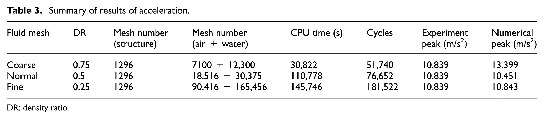
DR: density ratio.
Contact stiffness
Furthermore, it is the most difficult to determine the correct contact stiffness for FSI problem. In other word, a correct contact stiffness which affects the coupling forces is given to achieve a correct FSI. Very low contact stiffness will lead to numerical fluid leakage across a Lagrangian surface, but bigger contact stiffness results in numerical noise and high-frequency signals.
23
Therefore, the selection of contact stiffness is required here based on the penalty coupling algorithm. The coupling stiffness via the parameter PFAC, the penalty factor, in *CLIS is analyzed in detail. The contact stiffness is computed by the coefficient
It shows that the larger mesh density results in the smaller grid, and the greater contact stiffness; on the contrary, the smaller mesh density leads to the larger grid, and the smaller contact stiffness. Therefore, the contact stiffness is increasing with the growth of penalty factor value.
Figure 8 shows that the impact acceleration time histories are almost identical as the body enters the clam water, with some minor oscillation near the acceleration peak. Therefore, the influences of the coupling stiffness factor on the impact load, including the displacement and velocity responses, are small.

Impact acceleration for different PFAC values in *CLIS.
Time-step size
The proper time-step size termination is a very important factor for convergence study, together with mesh density analysis in the water impact event. If the characteristic element is smaller, the shorter time-step size will be needed because time-step is linked to the shortest duration for an acoustic wave to travel across any element of the models. Consequently, small time-step will increase the computation time in the same numerical analyses. The central difference method of LS-DYNA codes is conditional stable. The time-step size must not exceed a critical time-step size for numerical stability reason. A safety factor, TSSFAC in *CONTROL_TIMESTEP card, is applied to automatically compute the time-step. In present work, the time-step is read from the ASCII file of massage in practice. The time-step size for the models with DR = 0.75 is 1.96 × 10⁻⁷ s, 1.32 × 10⁻⁷ s for DR = 0.5, and 6.61 × 10⁻⁸ s for DR = 0.25. It is found that the time-step size is proportionally decreased with the reduction of the mesh DR.
Validation and results
Numerical models of the experiment scenario are created and employed based on Lagrangian formulation in the structure model and ALE formulation for fluid models. Meanwhile, a penalty coupling algorithm is used to predict the FSI loads with reference to the parameters selection previously described through the convergence study. The dropping structure with rigid body material takes into account no deformation or roll motion. Water surface is taken as the calm surface without the ripple and surface tension effects. During the analysis, the acceleration of gravity is not negligible in order to accurately simulate the impact velocity time histories.
For deeply verifying the new experimental and numerical results, the impact drag coefficient is introduced because it is independent of entry velocity, and the dropping height of the tests. Figure 9 shows the comparisons of the experimental, theoretical, and numerical drag coefficient. The experimental data are based on the Doppler measurement as explained in section “Experiment apparatus and measurement.” The most concerned result is the maximum impact forces in the early water entry. In the view of the acceleration peak and the overall shape of the curve, the prediction of nonlinear LS-DYNA codes coincides very well with ones derived from the analytical MLM and shows a quite satisfactory agreement. And then the theoretical value drops more quickly and numerical curve climbs in advanced due to the consideration of the water-entry cavity in the second water impacting phase.

Numerical–analytical–experimental correlation for the impact drag coefficient.
The numerically predicted water impact loads are synthesized for the same impactor at three different dropping heights as shown in Figure 10. Figure 10(a) illustrates the penetration depth time history during the initial impact stage. The maximum dropping height 190 causes the highest entry velocity in Figure 10(b) and consequently the largest impact forces in Figure 10(c).
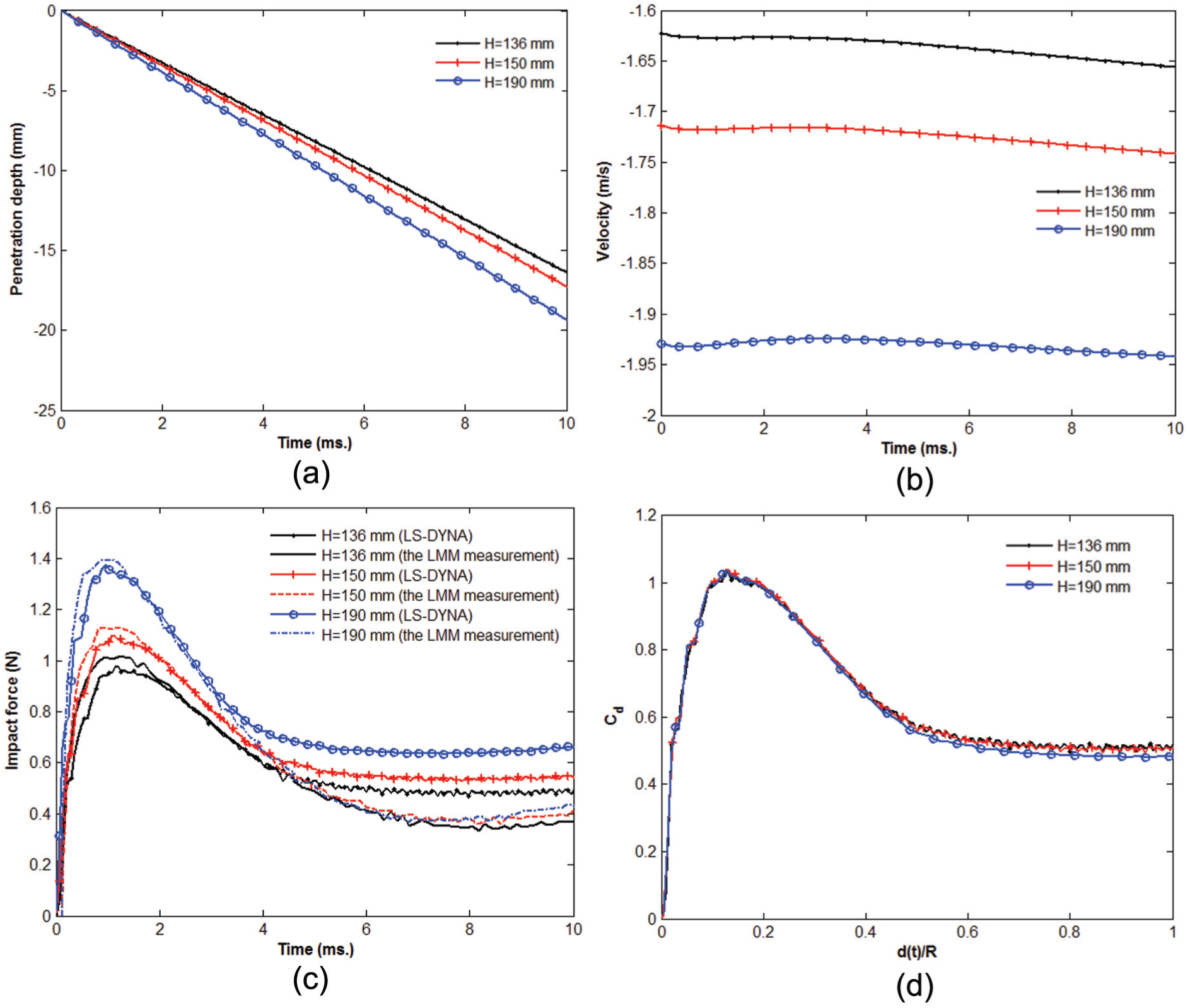
Impact loads with three different dropping heights.
The penetration velocity relatively remains the constant, although the tendency of penetration velocity is decreasing for all small-velocity test runs. The graphs demonstrate that the assumption of a constant entry velocity can be applied to the theoretical and numerical analyses, and the impact drag coefficients of drop velocity and constant velocity coincide well at the initial stage. 12 Figure 10(c) gives the comparisons between the numerical and experimental results about the relationship of impact force time histories. The numerical results follow the trend of experiments with the peak value deviating more than numerical results, especially in the region between 0.2 and 1.7 ms. The reasons could be the interaction of the reflection pressure waves from the tank walls with the pressure around the wetted surface of the spherical body. Due to higher speed of sound in water fluid, the pressure waves rise from the tank walls increase the pressure of the wetted surface of the spherical body, causing high upward impact forces.
Three experimental cases are numerically performed using ALE method and comparing the impact drag coefficient with the time delay as shown in Figure 10(d). It concludes the dependence of the drag coefficient Cd on the drop height. It can be numerically seen that the drag coefficients rise sharply when the spherical body impacts the water surface and then decrease, as happened in the experiment. It can be conjectured that water piles and jets consume much kinetic energy, resulting in further decrease of flow resistance.
And then the numerical results are bigger when water-entry penetration depth is more than half the radius of spherical body. It is because the process of water-entry cavitation formations is difficult to be dynamically simulated. And the interaction between the wetted surfaces with water flow only involves few elements because of cavity ventilation. Water ripple, water surface tensile, viscosity, and test article with smaller entry velocity can possibly cause the impact force peak by LMM higher than the numerical results. The peak value predicted from the numerical calculations and experimental measurements is reached almost at the same time. The peak values of water-impact load shown in Table 4 are given to assess of the numerical accuracy of the results.
Accuracies of numerical results.

The change of velocity during the entry period of less than ½R of sphere, similarly like a sinusoidal curve, can be negligible because the change is only about 0.001 m/s. It is the reason that the most analytical analysis is based on the constant velocity during the initial water entry. However, physically fluid surface is violently disturbed by the kinetic energy of the spherical body. The impact force enforces the spherical body to decelerate and the total energy loss is dissipated into the fluid around the spherical body to partly form the flow jet.
As seen in Figure 11, it is seen that the impact drag coefficients are nearly identical within range of [0, 0.5] which indicates that the drag coefficient is independent of the dropping height and the same to the maximum impact forces. Then the drag coefficients begin to show the difference with the several of water-entry velocity after the dimensionless depth of 0.5. However, the curve is relatively flat implies the impact drag coefficients remain essentially unchanged because the Reynolds number is lower than 2 × 10⁵.

Flow jet patterns and surface elevation state films from the records of simulations and tests.
Figure 11 graphically shows a selected number of screenshots of a spherical body vertically penetrating the free water surface for a drop height of 136 mm. The propagation of a flow jet along the outer surface of the body and the water surface elevation can be clearly seen. The spherical body is represented by the node assemble, and deep blue color domain is water fluid.
The LMM measurement can accurately measure water impact loads in order to evaluate the validity and efficiency of numerical models. But the limitation of LMM measurement for water impact problem is as follows. First, the penetration depth is not bigger than nearly a diameter of the spherical body because water splash will interrupt the signal beam of the optical interferometer. Second, the range of drop height is limited to about [60 mm, 190 mm] due to the measure capability of the digitizer. 20
Conclusion
The present work is to mainly verify and compare the LMM measurement with the classical experiment and analytical methods, together with numerical simulation methods. The drop tests utilized by the LMM measurement are performed on a rigid spherical body with different drop heights. The first goal of the study is to develop a water drop experiment using the LMM measurement and obtain perfect data for numerical validation purpose. The impact drag coefficient time histories, as assessment index, are compared with other classical experimental results, the analytical method, and numerical results. The main interest of the numerical simulations has been performed by a multi-material ALE solver and a penalty coupling algorithm in LS-DYNA codes. The structure is generally treated as formulations and FSI is used for coupling with the ALE domain. Sophisticated EOS control the behavior of fluid transmissions. The numerical results are compared to the LMM measurements with high-speed camera images. The main results of the research are emphasized as follows.
First, the good agreement is obtained at the initial entry stage between the determinations of the impact drag coefficient by the new measurement and other classical experimental results. The repeatability and the reliability of the tests of impact forces are showed the effectiveness of the crashworthiness design. The LMM measurement appears to be a very effective measure tool in the application of water impact problem.
Second, numerical model can be improved with the accurate experimental data which obtained using the modified LMM experiments. In the view of the peak values and the overall profile of the curves, the numerical predictions of nonlinear LS-DYNA codes coincide very well with the LMM measurement results. And then the verified numerical model can estimate the efficiency of the nonlinear explicit codes to predict the dynamic responses of the sphere-bottomed structure such as space capsules.
Finally, parameters selection and convergence study in simulation are implemented and verified by the experimental results. Especially, the focus is on study mesh sensitivity which is highly dependent on the relationship between the ALE and the Lagrangian mesh size.
Not only computation time but also the numerical solutions are dependent on the time-step size. Mesh DR is determined through the convergence analysis because the influence is the maximum. Considering the trade-off of the accuracy and the computation expense, the mesh DR is selected 0.5 near the contact domain, and the penalty factor is 0.1. Sizes of ALE fluid elements were advised to be smaller than the Lagrangian structural shell elements to get the best coupling quality. The reasonable time-step sizes may be automatically calculated and adjusted to the satisfactory solution according to the equivalent mesh length. Acceptable numerical predictions compared to experimental results and the numerical–experimental correlation are obtained and extensive investigations can be further applied to aircraft water landing problems.
Footnotes
Acknowledgements
The strong support for the numerical research is greatly appreciated because of the offering of ANSYS/LS-DYNA from NPU and NTU.
Handling Editor: Yucheng Liu
Declaration of conflicting interests
The author(s) declared no potential conflicts of interest with respect to the research, authorship, and/or publication of this article.
Funding
The author(s) disclosed receipt of the following financial support for the research, authorship, and/or publication of this article: The work has been done in the framework of the Joint Funds project of the National Natural Science Foundation of China (grant nos U1333133, U1733203, U1733105, and U1433126). The work related to the experiment was supported in part by the Grant-in-Aid for Scientific Research (B) 18824360156 (KAKENHI 24360156) in Japan.