Transient free convection in a composite enclosure having a cold flexible plate and a hot rigid plate is simulated numerically. It is assumed that the flexible plate is hyper-elastic. A porous layer with various sizes and permeabilities is attached to the rigid plate. The enclosure is filled with water. Fluid flow in the fluid domain was governed by the Navier–Stokes equations, and the flow within a saturated porous layer was governed by the Brinkman-Forchheimer extended Darcy model. The unsteady continuity, momentum, and energy equations are solved using the Arbitrary-Lagrangian-Eulerian (ALE) approach based on the fluid-structure interaction (FSI). It is found that the development of convective flow goes through initial, transitional, and stationary states. Each state interval is shifted by varying the Darcy number and Rayleigh number. In the transitional state, the deformation of the flexible parts reaches its maximum bending. The profile of the flexible plate at steady state is in a sinusoidal shape for the non-Darcy regime, while it is in an asymmetric parabolic shape for the Darcy regime. The steady state is reached for , , and before .
Free convection problem in a porous enclosure is important in industrial and geological implements. In many cases, the porous medium has multiple layers with different permeabilities and porosities, and the enclosures are composites with a fluid part and a porous part. Beckermann et al.1 studied theoretically free convection in the composite enclosure. A different configuration was later studied by Beckermann et al.2 They found that increasing the permeability and heating intensity increased the amount of fluid penetrating the porous part. Chen and Chen3 considered again the free convection in the composite enclosure. Free convection of a binary fluid with porous medium integrated was studied by Goyeau et al.4 Chen et al.5 looked at porous parts installed on the top and bottom walls and discovered that the porous size, permeability, and heat intensity all influence the heat transfer rate. Ismael and Chamkha6 considered the composite enclosure, where a nanofluid part and a porous part were arranged side by side. Baytas and Baytas7 updated the energy equation by considering the non-equilibrium model for certain parameters. Recently, Alsabery et al.8,9 concluded that increasing the porous thickness enhance the heat transfer rate. Al-Srayyih et al.10 concluded that the thermal performance keeps its maximum value until the porous thickness exceeds the critical threshold of 0.3. Raizah et al.11 concluded that the thermal performance achieves its highest value in the scenario of a horizontal heterogeneity porous layer. Moria12 demonstrated the importance of porous layers in improving the natural convection of an L-shaped enclosure. Venkatadri and Beg13 found that higher Darcy and Rayleigh numbers increase Nusselt number at the hot and cold walls.
The heat transfer area observed within a composite enclosure with rigid surfaces drew the majority of subjects. The newly formed material affords a flexible surface with an adjusted elasticity, is extremely thin, and has several thermal properties. For instance, inelastic water performs many tasks beneath the expected radiation within solar drying, and an extremely thin membrane layer protects the sensitive electronic segment where the membrane acts highly elastic and influences the fluid circulation. A flexible wall is shifted or oscillated periodically, causing a deformable domain, and the fluid exerts a force on the flexible solid subject to a stress boundary condition. Engel and Griebel14 mentioned that the effect of the flexible deformations of the solid on the fluid is given by the position and the velocity of the moving boundary. He presented the contour of velocity and displacement at the interface due to the forces exerted by the fluid movement on the flexible structure. There were considerable differences in the structure of flow fields between the elastic and rigid wall aortic aneurysm models as reported by Khanafer et al.15 Alamiri and Khanafer16 numerically studied convection in a lid-driven cavity with a flexible bottom surface. Khanafer17 made a comparison of the isotherms, streamlines, and Nusselt numbers between rigid and flexible right walls. Their observation indicated that heating intensity and the elasticity of the flexible surface had a penetration impact on the form of the flexible surface and consequently on the heat transfer enhancement. Later, Khanafer18 performed a comparison between the flexible and wavy geometry regarding the heated bottom surface. Contrary results were reported by Wang and Davidson19 where the performance of the flexible manifold was lower than the performance of the rigid manifold due to the collapse of the manifold entrainment in solar water heaters. Selimefendigil and Oztop20 considered the MHD mixed convection within a flexible walled lid-driven cavity filled nanofluids having volumetric heat generation. Jamesahar et al.21 studied a perfectly thermal-conductive flexible diagonal partition. Raisi and Arvin22 looked at the top elastic wall and found that increasing the Rayleigh number improved heat transfer and increased the deformation of the flexible parts. Selimefendigil and Oztop23 investigated a localized heated triangular enclosure filled with nanofluid and containing a partially elastic surface that generated internal heat. Selimefendigil et al.24 investigated the interaction of nanofluid and magnetic field inside a lid-driven cavity with an elastic side wall. Then, Selimefendigil et al.25 extended to the lid-driven cavity with elastic top wall. Later, Selimefendigil26 studied a flexible bottom wall subject to a conductive inner L-shaped obstacle in vented cavity. Selimefendigil and Oztop27 reported 11% heat transfer enhancement utilizing the flexible in an inclined L-enclosure. Alsabery et al.28 examined the case of heat transfer and entropy generation within a 2D cavity including a flexible right surface and an active rotating cylinder. Ghalambaz et al.29 looked into a square enclosure divided by a flexible membrane and controlled by non-uniform temperature heating. The elastic plate was found by Mehryan et al.30 to have the lowest deformation and tension if located at the center. Mehryan et al.31 found that heat performance and the wall tension enhances by the increasing the heating intensity. Shahabadi et al.32 reported that the heat transfer rate at the hot wall do not follow the modulus Young value. Shahrestani et al.33 concluded that the overall stress exerted to the surface will be increased over 70 times by increasing the Prandtl number from 0.71 to 200. Ghalambaz et al.34 found that the pseudoplastic fluid boosts the heat transfer enhancement from the flexible heater. Al-Amir et al.35 observed that the bottom wall of the enclosure is highly sensitive to the flexible wall, but the top wall’s Nusselt number grows with Hartmann number regardless which the wall is flexible.
Prior research focused almost entirely on two distinct cases: convection in an enclosure with flexible walls and convection in composite enclosures without flexible walls. Thus, the present numerical study aims to analysis fluid structure interaction on natural convection within a composite enclosure having flexible wall. Accordingly, the main novelty of this study is the investigation of the co-effect of wall deformation and porous thickness on fluid circulation. In addition, simultaneous influence of the time interval and the heating intensity on heat transfer properties is studied using the Brinkman-Forchheimer model. The physical model presented in this study can be a specimen of composite enclosures where the flexible walls can help to protect sensitive electronic components from damage caused by impacts or vibrations. The flexible wall layer absorbs these shocks and dissipates the convection, lowering the chance of component damage. Furthermore, the flexible wall layer can aid to prevent vibration transmission from external factors such as machinery or other devices.
Mathematical formulation
A model diagram and coordinate system of the model are sketched in Figure 1. The model depicts unsteady free convection and heat transfer in a Newtonian and incompressible liquid enclosed in a composite enclosure with a size and a right flexible wall. The left wall of the container is at a hot isothermal temperature (), while a cold temperature () is confirmed at the flexible wall. On the other hand, the thermal insulation situation is maintained at the horizontal walls. Considering 2D model with the following assumptions:
Incompressible flow,
The Boussinesq approximation is valid,
The Brinkman-Forchheimer-extended Darcy flow model,
Vertical interface between the fluid and porous layers is permeable,
All outer boundaries are impermeable,
A simple hyper-elastic wall material at the right,
Fluid filling pores and the solid matrix are in thermal equilibrium,
Homogeneous and undeformable pores in the porous layer,
Negligible viscous dissipation, radiation, Soret, Joule-heating, and Dufour effects.
Schematic diagram of the composite enclosure.
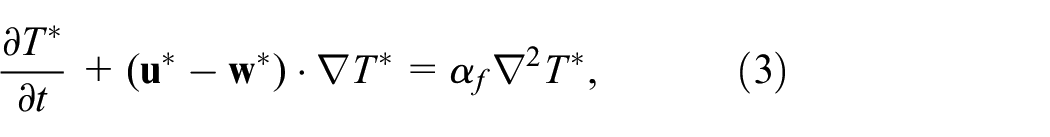
Using the pointed out assumptions, the dimensional principal equations in the Arbitrary Lagrangian-Eulerian (ALE) formulation can be written as28:
where denotes the fluid velocity vector, represents the velocity vector of the moving mesh. Here, and represent the pressure and temperature fields. The symbols of , , , and denote the thermal diffusivity (liquid and the structure), density, thermal volume expansion, and the kinematic viscosity, respectively. The gravitational acceleration is indicated by .
The deflection of the flexible thin wall is evaluated as given by Haghani et al.36:
where , , and shows the stress tensor, the motion of the wall structure, and the imposed volumetric forces, respectively. The hyper-elastic model was used to simulate the motion of the wall structure while the Neo-Hookean model was employed to evaluate the stress tensor, :
in which
In the above equation, indicates the transpose operation. The strain (), and its energy density () could be formulated as given by Jamesahar et al.21:
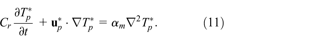
in which, the Lame first and second constants could be introduced by and . Here, denotes the primary invariant for the tensor of Cauchy-Green displacement. The Poisson’s ratio and the Young modulus are indicated by and . The continuity, momentum, and energy equations of the porous part are:
Here is the porous temperature. The symbols is the porous velocity vector. The ratio of composite material heat capacity to convective fluid heat capacity is , is the porosity, is the permeability, and is the Forchheimer constant.
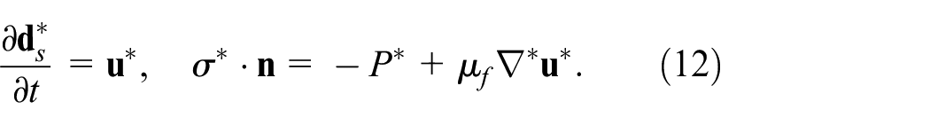
Finally, the continuity of displacement and forces at the wall-liquid interface were adopted as the boundary conditions:
The continuity of heat flux and temperature were employed at the interface of a thin wall and the liquid:
The boundary condition at the porous to fluid interface are:
Where is the effective dynamic viscosity defined as , is the effective thermal conductivity defined as . The is the conductivity the flexible wall and here . The thickness of the flexible wall is set at 0.000012.
Now, invoking the following non-dimensional parameters:
The porous and fluid layers governing equations are combined as given by Omara et al.37 and Jamesahar et al.,21 then it is stated as:
Where , , for fluid layer and , , for porous layer. In the above, and stands for the thermophysical ratios of the thermal diffusivity and density, respectively while represents the Prandtl number. Here, the impact of the buoyancy body force on the structure was ignored which leads to . is the ratio of thermal conductivities. The initial velocity and temperature are considered 0 and 0.5, respectively. The dimensionless boundary conditions of equations (18) to (20) are:
On the left surface:
On the flexible wall:
On the adiabatic top and bottom horizontal walls:
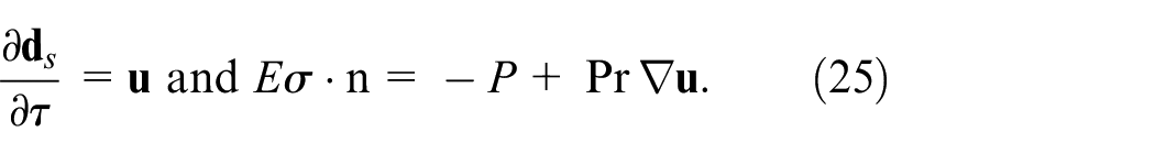
The boundary conditions on the flexible surface were derived as:
The characteristic parameter of heat transfer is the Nusselt number (), which corresponds to the rate of heat transfer across the enclosure. The heat transfer rate at the at the hot rigid wall is given by:
Integration over the local Nusselt number leads to the average Nusselt number, (), which denotes the average of heat transfer rate across the enclosure:
Computational methodology
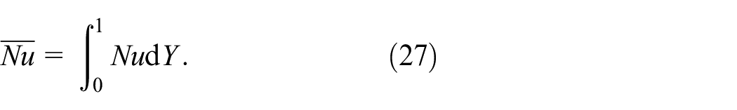
The dimensionless governing equations in equations (18) to (21) subjected to the initial and boundary conditions in equations (22) to (25) are determined numerically by COMSOL 5.4. COMSOL is a general-purpose solver of interlinked differential equation based on the Galerkin finite element method (GFEM). This method is simple, compact, and result-oriented, making it widely popular among the engineering community. Modeling complex geometry and boundary conditions is easier than with other approaches since a wide range of finite elements are available for domain discretization. The first step is to create the geometry of the model. The next step is defining the parameters such as , , , , , and others. Selecting the FSI and HT modules is the next step. This involves specifying the equations (22) to (25). Then the mesh is generated as shown in Figure 2. The next step is to set up the simulation and run then compute the solution. The final step is to visualize and analyze the results.
Mesh distribution for a mesh size 6369 at different time for and : (a) τ = 0.0005, (b) τ = 0.0015, (c) τ = 0.015, and (d) τ = 1.5.
To ensure the independence of the present numerical solution from the mesh size of the numerical domain, we have used different mesh sizes to calculate the minimum strength of the flow circulation () and average Nusselt number () for the case of , , , and . The results are shown in Table 1 indicate insignificant differences for the extra-fine mesh and above. Therefore, for all computations in this paper for similar problems to this subsection, the extra-fine uniform mesh is employed.
Mesh testing for and at different mesh sizes for , , , and .
Predefined mesh size
Number of elements
CPU time(s)
Coarse
3393
19.5008
−40.913
257
Normal
3891
19.6238
−40.718
259
Fine
4699
19.7222
−40.304
298
Finer
5329
19.7554
−39.932
339
Extra-fine
6369
19.7956
−39.791
421
Extremely-fine
7845
19.9216
−39.896
466
Verification of the current streamlines and isotherms was made against that of Beckermann et al.1 for the rigid wall in the case , , , , and (see Figure 3). In addition, Table 2 exhibits a validation by computing the values of for several values of and for a horizontal porous layer in Darcy model at and . As it can be seen from the above tables, in each case, the outcomes are considerably consistent with those in the literature and these comparisons give support to the present technique, which can produce acceptable results.
Comparison of the current streamlines and isotherms (left) against that of Beckermann et al.1 for rigid wall at , , , , and .
Comparison of present for horizontal porous layer case in Darcy model at and .
In order to validate the FSI, elastic wall, different validation is conducted by comparing the published work, Mehryan et al.39 for the FSI model and convective heat transfer inside enclosure that uniformly divided with elastic wall for , , , and , as demonstrated in Figure 4. According to these comparisons, the current results are noticeably consistent when compared to previously published works.
Streamlines (a) and isotherms (b); Mehryan et al.39 (left) and present study (right) for , , , and .
Results and discussion
The investigation into this work is directed toward the following specialty about the associated dimensionless combinations: the porous thickness, ; the Darcy number, ; Rayleigh number, . The time is in the range of . The Rayleigh number, to keep the convection in laminar regime and the applicability of Boussinesq approximation. The Darcy number, to cover a pore-level in the Darcy and non Darcy models. The porous thickness, and the time, were used to show the impacts of the layer size on the transient or steady convection. The modulus Young is taken as and the thermal conductivity ratio is taken as . The Prandtl number and the porosity are fixed at and , respectively.
Figures 5 and 6 depict the time evolution of streamlines and temperature contours for the case of , , , and . At the early time, that is, , the elastic cold wall is straight, and there is a very weak convective flow in the enclosure. The distance between the streamlines is quite large. Figure 6 also shows that all of the enclosure is at the constant cold temperature of at the initial time except a narrow region around the hot wall. Figure 6(c) shows a plume of hot fluid moving toward the top wall of the enclosure. When the rigid hot wall heats the fluid, decreases density and consequently, it circulates upward due to the buoyancy effect. Figure 6(c) shows the beginning of the bending of the elastic wall at the top right corner of the enclosure. The heated fluid exits the hot wall and circulates horizontally along the top boundary until it reaches the elastic wall in the top-right corner. Here, the fluids change their direction from horizontal to vertical, toward the bottom boundary. As a result, the elastic wall experiences a force in the opposite direction of the fluid circulation. Hence, the cold wall at the top is concave. After a while, a strong convective flow takes action in the enclosure. In the steady phase, the hot fluid circulates upward and follows the top boundary until it reaches the elastic wall. The fluid adjacent to the elastic wall circulates downward toward the bottom wall and loses its energy. Figure 5(f) exhibits a large bending of the elastic wall at the upper part, which is a concave shape. The streamlines in Figure 5(h) show that the cold fluids circulate along the cold wall and leave the wall before they reach the bottom. When the fluid leaves the cold wall, it produces a low-pressure area at the bottom, which imposes a weak tendency for the flexible wall to move toward the enclosure and form a convex shape. Finally, due to the conservation of mass, the total volume of the enclosure remained equal. Hence, the bottom part of the elastic wall formed a convex shape to balance the total volume change.
Time evolution of the streamlines at , , , and . (a) τ = 0.0001, (b) τ = 0.0006, (c) τ = 0.0018, (d) τ = 0.003, (e) τ = 0.01, (f) τ = 0.03, (g) τ = 0.035, (h) τ = 0.2, and (i) τ = 1.0.
Time evolution of the isotherms at , , , and . (a) τ = 0.0001, (b) τ = 0.0006, (c) τ = 0.0018, (d) τ = 0.003, (e) τ = 0.01, (f) τ = 0.03, (g) τ = 0.035, (h) τ = 0.2, and (i) τ = 1.0.
Figure 7 and shows the influence of the porous thickness on the stationary streamlines and stationary temperature contours for , , and . The behavior of the streamlines at the top and bottom walls is almost identical. This is since the hot fluid moves toward the top wall regardless of the shape of the wall, and then the fluid stream will be controlled by the horizontal wall. Similarly, when the cold fluid leaves the cold wall, it reaches the bottom wall and moves along the wall horizontally. Figure 7 also shows that the thickness has minor effect on the bending of the elastic wall. The effect of porous thickness on the hydraulic behavior in the core region is limited as long as the thermal layer surrounds the rigid wall. As previously stated, the thickness solely impacts the left region, which is near to the inflexible hot wall, whereas momentum exchange forces mostly occur at the top and bottom of the cold wall. As a result, the parameter has no effect on the elastic wall’s sinusoidal shape. The streamlines and hot flow move toward the top wall, so that the influence of such a change in the flow path can be seen in the isotherm contours. More distortion is observed by thinning the porous layer. This is due to the fluid layer size modifying the inner heat circulation in the enclosure, especially at high heating intensities.
Variation of the streamlines (left) and isotherms (right) evolution by porous thickness for , , and . (a) S = 0.0, (b) S = 0.2, and (c) S = 0.3.
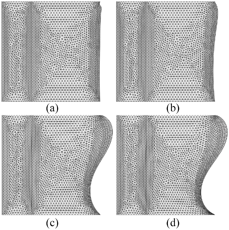
Figure 8 illustrates the effect of the Darcy number on the steady streamlines and steady isotherms for , , and . This figure interestingly shows that the variation of the Darcy number induces a maximal impact on the general behavior of the streamlines and isotherms in the enclosure. The hot rigid wall heats the fluid, and consequently, a stream of hot fluid forms over the rigid wall toward the top. When the isotherms at the hot plate are looked at, it can be seen that a thermal layer of hot fluid always covers the hot plate for the Darcy number that is being looked at. The thermal layer gets heated and moves upward. Indeed, when the permeability is high, the heated layer of fluid covers the entire hot wall and damps the hydraulic impact on the wall shape. The impact of such a change in the flow path can be seen in the isotherm contours. The elastic plate has an asymmetric parabolic shape in the Darcy regime, and the elastic wall has a sinusoidal shape in the non-Darcy regime. When the permeability is high in a non-Darcy regime, it allows fluids to pass and generates maximal mechanical power for the flexible plate. Moreover, the momentum exchange forces mainly take place at the middle plate. Hence, the flow changes the geometry of the elastic plate into a sinusoidal shape. The sinusoidal shape has a favorable effect that increases the flexible wall’s contribution on enhancing energy transfer. Therefore, larger Darcy numbers tend to have greater flow circulation than lower Darcy numbers. Previously, Alkhalidi et al.40 indicated that the concave shape of the rigid wall reduces the flow circulation.
Variation of the streamlines (left) and isotherms (right) evolution by Darcy number for , and . (a) Da = 10−5, (b) Da = 10−3, and (c) Da → ∞.
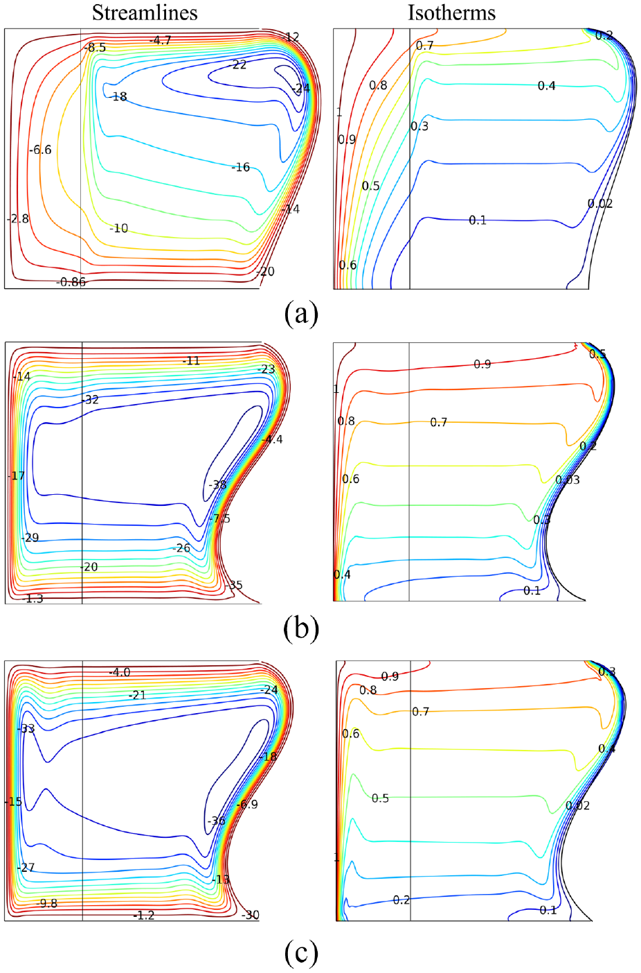
Figure 9 exhibits the impact of Rayleigh number on the streamlines and isotherms at the stationary state conditions for , , and . When the Rayleigh number is small, the flow circulation is weak, and hence, the momentum exchange between the elastic wall and the fluid circulation is poor. When the Rayleigh number is small, the convective flow generates a circular vortex, and the isotherms deviate slightly, especially inside the porous layer, as shown in the streamlines. The core vortex elongated vertically and shifted to the cold, elastic boundary as the Rayleigh number increased. The fluid’s motion coincides with its enthalpy change, which is proportional to the strength of the heating. So, the advantages of using an elastic wall could be significant at high Rayleigh numbers. Profile of the flexible plate is in a sinusoidal shape for the strong convection intensity. This indicates that improved heat transmission can be accomplished by introducing strong convection into flexible walls. The extent of buoyancy force will depend on the temperature difference between the fluid and the wall. The convective flow is exerting a force on the wall, which causes it to move. Overall, the effect of convection on a flexible wall will depend on the Rayleigh number.
Variation of the streamlines (left) and isotherms (right) evolution by Rayleigh number for , , and . (a) Ra = 105, (b) Ra = 106, and (c) Ra = 107.
The impact of the length of porous layer and Darcy number on the steady local Nusselt number are displayed in Figure 10(a) and (b), respectively. In Figure 10(a), the results are plotted along the left wall. From Figure 10(a), it can be seen that there is substantial convection heat transfer at the bottom of the wall, regardless of the length of the porous layer and Darcy number. This is where the stream of the cold fluid reaches the wall. The general trend of the local Nusselt number is decreasing as the distance from the bottom wall increases. Interestingly, the Nusselt number in the case of are comparable to that of and . The increase of the Darcy number increases the capacity of a porous material to transmit fluids, and hence, the larger temperature gradient. means the full capacity of a porous material to transmit fluids and in this work similar to case . The co-effect of pore and porous layer size generating more hot fluid that diffuses during convection causes the fluid velocity to increase, which implies the maximum temperature gradient is above the value of .
Variation of steady local along the left wall for different porous thickness (a) and Darcy number (b) at and .
Figure 11 shows the time history of the average Nusselt number for various size of the porous part (a) and Darcy number (b) at and . This figure reveals that the size and permeability effects are significant at the early, transitional, and steady stages. The phase time ranges are locked by changing the Darcy number or . There is no wavy pattern observed at Darcy regime (). The wavy pattern at the transitional stages related the oscillatory deformation of the elastic wall and it free from the effect of the porous size. The higher the Darcy number, the higher the wavy pattern shown at the transitional phase. The steady state is reached for , , and before . At and , the porous and fluid parts stretch out from the hot to the cold plate, resulting in the same total temperature drop across the enclosure. At steady state, the Darcy number has a moderate impact on the local Nusselt number and a large impact on the local Nusselt number during the transitional phase. However it induces less impact on at the initial phase. In the early stage, the variation of and could induce a small impact, in parallel with the contours of streamlines and isotherms discussed in previous figures. The steady state is reached for the all cases of porous thickness before .
Variation of the unsteady with for different (a) and (b) at and .
Figure 12 explores the impact of Rayleigh number on the steady local Nusselt number for two cases of (a) and (b). Figure 12(a) shows an unfluctuating Nusselt number for the case of . When at the Darcy regime, the fluid movement is slow, and the convection effects are small. The higher the Rayleigh number, the higher the overall local Nusselt number, except near the bottom, left corner. At the top right corner, the local Nusselt number of is slightly below the local Nusselt number of and . In Figure 12(b), it can be seen that the increase of Darcy number boosts the convective flow. The highest local Nusselt number appears near the top left corner. The highest local Nusselt number corresponds to regions where hot fluid diffuses and temperature gradients are high. When the Rayleigh number is reduced, the flow circulations weaken and the temperature gradients decrease, resulting in no heat transfer at the top, right corner. Following the streamlines and isotherms as the fluid moved unevenly, resulting in an unnecessary reduction of the temperature gradients at the top, right corner. Attention to these figures shows that the greatest cross-flow along the fluid-to-porous boundary occurs at the bottom or top plates. In addition, a temperature gradient of two-fold magnitude is noticed in the bottom corner. When the flow velocity increases due to an increased Darcy number, the thickness of the thermal boundary layer is reduced. This allows for more efficient heat transfer since the heat has less distance to travel between the plate surface and the bulk fluid.
Variation of steady local along the left wall for different when (a) and (b) at and .
Figure 13 shows the time history of the average Nusselt number for various Rayleigh numbers for two cases of (Figure 13(a)) and (Figure 13(b)). Development of convection in Darcy and non Darcy regime goes through an initial phase at , a transitional phase at and a steady phase after for . The phase time ranges are shifted by changing the Rayleigh number. The steady state is reached for before . The wavy pattern in at the initial phase is because of the bending of the elastic wall. The higher the Rayleigh number, the higher the wavy pattern shown at the transitional phase. Finally at the stationary phase, the is much higher for stronger Rayleigh number in non-Darcy regime (Figure 13(b)). There are fee expectations at stronger convection intensity about and higher permeability where the fluid movement have the higher velocity and diffuses through the porous layer.
Variation of the unsteady with for different when (a) and (b) at and .
Conclusions
The fluid-structure interaction on natural convection in a composite enclosure with a flexible right wall was investigated in this study. The Navier–Stokes or Brinkman-Forchheimer equations, together with the energy equations, are solved numerically using the COMSOL program. The computational outcomes regarding flow and thermal distributions, as well as the overall heat transfer, were visualized graphically. The developments of streamlines, vortices, thermal patterns, and heat transfer forms were closely linked by the Darcy number, porous thickness, elasticities, and Rayleigh number. The significant findings concerning the existing investigation are as follows:
The development of convective flow goes through an initial state, a transitional state, and a stationary state. Each state range is shifted by varying the Darcy number and Rayleigh number. By varying the porous thickness, each state’s range is not affected.
During the transitional state, the elastic wall undergoes an oscillatory deformation. When the flexible parts’ deformation reaches its maximum bending, the deformation is minimized, and the stored energy in the flexible parts is transferred to the fluid flow.
The profile of the flexible plate at steady state is in a sinusoidal shape for , while it is in an asymmetric parabolic shape for . The steady state is reached for , , and before .
A substantial convection heat transfer at the bottom of the wall regardless of size of porous layer and Darcy number.
The theoretical prediction in this research should serve as a valuable guide for experimentalists studying composite enclosures under various porous layer thickness, Darcy and Rayleigh numbers. Further applications, the enclosure may be filled with two different fluids. Considering different elasticity of the flexible wall, venting element, different porosity, different effective thermal conductivity, and other thermophysical properties could be the subject of future research undertaking.
Footnotes
Appendix
Handling Editor: Chenhui Liang
Declaration of conflicting interests
The author(s) declared no potential conflicts of interest with respect to the research, authorship, and/or publication of this article.
Funding
The author(s) received no financial support for the research, authorship, and/or publication of this article.
ORCID iDs
Abeer Alhashash
Habibis Saleh
Data availability
The data used to support the findings of this study are available from the corresponding author upon request.
References
1.
BeckermannCRamadhyaniSViskantaR.Natural convection flow and heat transfer between a fluid layer and a porous layer inside a rectangular enclosure. J Heat Transf1987; 109: 363–370.
2.
BeckermannCViskantaRRamadhyaniS.Natural convection in vertical enclosures containing simultaneously fluid and porous layers. J Fluid Mech1988; 186: 257–284.
3.
ChenFChenCF.Convection in superposed fluid and porous layers. J Fluid Mech1992; 234: 97–119.
4.
GoyeauBLhuillierDGobinD, et al. Momentum transport at a fluid–porous interface. Int J Heat Mass Transf2003; 46: 4071–4081.
5.
ChenXBYuPSuiY, et al. Natural convection in a cavity filled with porous layers on the top and bottom walls. Transp Porous Media2009; 78: 259–276.
6.
IsmaelMAChamkhaAJ.Conjugate natural convection in a differentially heated composite enclosure filled with a nanofluid. J Porous Media2015; 18: 699–716.
7.
BaytaşAFBaytaşAC.Thermal non-eq28 natural convection in a square enclosure with heat-generating porous layer on inner walls. Transp Porous Media2017; 120: 167–182.
8.
AlsaberyAIChamkhaAJSalehH, et al. Darcian natural convection in an inclined trapezoidal cavity partly filled with a porous layer and partly with a nanofluid layer. Sains Malays2017; 46: 803–815.
9.
AlsaberyAIChamkhaAJSalehH, et al. Natural convection flow of a nanofluid in an inclined square enclosure partially filled with a porous medium. Sci Rep2017; 7: 2357.
10.
Al-SrayyihBMGaoSHussainSH.Natural convection flow of a hybrid nanofluid in a square enclosure partially filled with a porous medium using a thermal non-equilibrium model. Phys Fluids2019; 31: 043609.
11.
RaizahZASAhmedSEAlyAM.ISPH simulations of natural convection flow in E-enclosure filled with a nanofluid including homogeneous/heterogeneous porous media and solid particles. Int J Heat Mass Transf2020; 160: 120153.
12.
MoriaH.Natural convection in an L-shape cavity equipped with heating blocks and porous layers. Int Commun Heat Mass Transf2021; 126: 105375.
13.
VenkatadriKBégOA.Lattice Boltzmann simulation of thermo-magnetic natural convection in an enclosure partially filled with a porous medium. Waves Random Complex Media2022 Epub ahead of print 20 December 2022. DOI: 10.1080/17455030.2022.2157516.
14.
EngelMGriebelM.Flow simulation on moving boundary-fitted grids and application to fluid-structure interaction problems. Int J Numer Methods Fluids2006; 50: 437–468.
15.
KhanaferKMBullJLBerguerR.Fluid–structure interaction of turbulent pulsatile flow within a flexible wall axisymmetric aortic aneurysm model. Eur J Mech B/Fluids2009; 28: 88–102.
16.
Al-AmiriAKhanaferK.Fluid–structure interaction analysis of mixed convection heat transfer in a lid-driven cavity with a flexible bottom wall. Int J Heat Mass Transf2011; 54: 3826–3836.
17.
KhanaferK.Fluid–structure interaction analysis of non-Darcian effects on natural convection in a porous enclosure. Int J Heat Mass Transf2013; 58: 382–394.
18.
KhanaferK.Comparison of flow and heat transfer characteristics in a lid-driven cavity between flexible and modified geometry of a heated bottom wall. Int J Heat Mass Transf2014; 78: 1032–1041.
19.
WangSDavidsonJH.Fluid–structure interaction in the flexible porous stratification manifold. J Sol Energy Eng2016; 138: 011005.
20.
SelimefendigilFÖztopHF.Analysis of MHD mixed convection in a flexible walled and nanofluids filled lid-driven cavity with volumetric heat generation. Int J Mech Sci2016; 118: 113–124.
21.
JamesaharEGhalambazMChamkhaAJ.Fluid–solid interaction in natural convection heat transfer in a square cavity with a perfectly thermal-conductive flexible diagonal partition. Int J Heat Mass Transf2016; 100: 303–319.
22.
RaisiAArvinI.A numerical study of the effect of fluid-structure interaction on transient natural convection in an air-filled square cavity. Int J Therm Sci2018; 128: 1–14.
23.
SelimefendigilFÖztopHF.Mixed convection in a partially heated triangular cavity filled with nanofluid having a partially flexible wall and internal heat generation. J Taiwan Inst Chem Eng2017; 70: 168–178.
24.
SelimefendigilFÖztopHFChamkhaAJ.Fluid–structure-magnetic field interaction in a nanofluid filled lid-driven cavity with flexible side wall. Eur J Mech B/Fluids2017; 61: 77–85.
25.
SelimefendigilFOztopHFChamkhaAJ.MHD mixed convection in a nanofluid filled vertical lid-driven cavity having a flexible fin attached to its upper wall. J Therm Anal Calorim2019; 135: 325–340.
26.
SelimefendigilFÖztopHFAbu-HamdehN.Impacts of conductive inner L-shaped obstacle and elastic bottom wall on MHD forced convection of a nanofluid in vented cavity. J Therm Anal Calorim2020; 141: 465–482.
27.
SelimefendigilFÖztopHF.MHD mixed convection of nanofluid in a flexible walled inclined lid-driven L-shaped cavity under the effect of internal heat generation. Phys A Stat Mech Appl2019; 534: 122–144.
28.
AlsaberyAISelimefendigilFHashimI, et al. Fluid-structure interaction analysis of entropy generation and mixed convection inside a cavity with flexible right wall and heated rotating cylinder. Int J Heat Mass Transf2019; 140: 331–345.
29.
GhalambazMMehryanSAMIsmaelMA, et al. Fluid–structure interaction of free convection in a square cavity divided by a flexible membrane and subjected to sinusoidal temperature heating. Int J Numer Methods Heat Fluid Flow2020; 30: 2883–2911.
30.
MehryanSAMAlsaberyAModirA, et al. Fluid-structure interaction of a hot flexible thin plate inside an enclosure. Int J Therm Sci2020; 153: 106340.
31.
MehryanSAMGhalambazMKalantar FeeojR, et al. Free convection in a trapezoidal enclosure divided by a flexible partition. Int J Heat Mass Transf2020; 149: 119186.
32.
ShahabadiMMehryanSAMGhalambazM, et al. Controlling the natural convection of a non-Newtonian fluid using a flexible fin. Appl Math Model2021; 92: 669–686.
33.
ShahrestaniABAlshuraiaanBIzadiM.Combined natural convection-FSI inside a circular enclosure divided by a movable barrier. Int Commun Heat Mass Transf2021; 126: 105426.
34.
GhalambazMMehryanSAMFeeojRK, et al. Free convective heat transfer of a non-Newtonian fluid in a cavity containing a thin flexible heater plate: an Eulerian–Lagrangian approach. J Therm Anal Calorim2022; 147: 1809–1824.
35.
Al-AmirQRHamzahHKAliFH, et al. Comparison study of vertical and horizontal elastic wall on vented square enclosure filled by nanofluid and hexagonal shape with MHD effect. Eur Phys J Spec Top2022; 231: 2623–2643.
36.
HaghaniAJahangiriMYadollahi FarsaniR, et al. Transient fluid-solid interaction and heat transfer in a cavity with elastic baffles mounted on the sidewalls. Math Probl Eng2021; 2021: 1–15.
37.
OmaraATouikerMBourouisA.Thermosolutal natural convection in a partly porous cavity with sinusoidal wall heating and cooling. Int J Numer Methods Heat Fluid Flow2022; 32: 1115–1144.
38.
SinghAThorpeG.Natural convection in a confined fluid overlying a porous layer-a comparison. Indian J Pure Appl Math1995; 26: 81–95.
39.
MehryanSAMGhalambazMIsmaelMA, et al. Analysis of fluid-solid interaction in MHD natural convection in a square cavity equally partitioned by a vertical flexible membrane. J Magn Magn Mater2017; 424: 161–173.
40.
AlkhalidiAKiwanSAl-KouzW, et al. Rarefied flow and heat transfer characteristics of rectangular cavities with heated concave surface. Adv Mech Eng2019; 11: 1687814019860988.