
Abstract
Transient conjugate free convection in flexible enclosure is examined numerically. Isoflux heat sources are mounted in a left wall of finite thermal conductivity while a right wall is assumed to be hyper-flexible. The finite element method (FEM) is adopted to solve the governing partial differential equations, an arbitrary Lagrangian–Eulerian (ALE) approach inherent in the unstructured mesh. The governing parameters under consideration are: the number of the heat source,
Keywords
Introduction
Free convection has been selected as the heat transfer mechanism for electronic cooling. This is due to low-cost operation, the quietest, independent from electromagnetic effect and the most important this is a very high reliability. The electronic circuits or components may be mounted to one vertical wall of an electronic casing or an enclosure. The component heating is discrete and can be highly non-uniform heat source. An optimal arrangement of the discrete heaters has been addressed in the literatures. Ho and Chang 1 study of free convection in an enclosure with discrete heater. Heindel et al. 2 found that the discrete heater no longer have their thermal identity. Sezai and Mohamad 3 put a discrete heater on the bottom of the enclosure. da Silva et al. 4 concluded that the optimal distribution is not in equidistant arrangement and as the heating intensity increases the heat sources must be installed near the tip of a boundary layer with zero spacings. Three discrete heaters was attached on the vertical wall by Bae and Hyun. 5 Chen and Chen 6 obtained the two different thermal boundary conditions appear following heat sources arrangement on the vertical and horizontal walls. Müftüoğlu and Bilgen 7 investigated when the discrete heater were varied from one to three various size. They concluded that the heat transfer and flow rates are increasing function of heating intensity, heater size, and number of the heaters. Sankar and Do 8 reported that the thermal performance is always higher at the bottom heat source. Lopez et al. 9 indicated that the flow evolves into three categories: the first when vertical levels below the heat source, an essentially low temperature, stagnant pool is formed, and the heat flow through the outer pool is zero. Nardini and Paroncini 10 and Nardini et al.11,12 sequentially investigated free convection with multiple discrete sources using experimental and theoretical approach. Different configuration of hot wall locations have been identified by Mahapatra et al. 13 to enhance the heat transfer, thermal mixing, and thermal uniformity distribution. Elsherbiny and Ismail 14 considered the tilted enclosure having two localized heat sources. Naffouti et al. 15 concluded that the increasing heating intensity and the distance between the heaters increase the heat transfer rate. They also showed that the most influential factors on flow and heat transfer rate were heater height and aspect ratio. Nayaki et al. 16 set the array isoflux heaters. El-Moutaouakil et al. 17 studied that the heated cavity from six identical isothermal elements put on the walls and observed that the case uniform arrangement 2 × 2 × 2 leads to the maximum thermal performance. Parveen and Mahapatra 18 considered nanofluid heat transfer in a wavy enclosure with a central heating element.
Most studies of discrete heaters in enclosures have focused on rigid surfaces. However, recent advances have introduced a novel material that provides a flexible surface with customized elasticity, extreme thinness, and unique thermal properties. For example, in applications such as inelastic water distribution tasks under expected solar radiation for drying processes. In such cases, a very thin membrane case shields sensitive electronic components. This membrane exhibits high elasticity and is influenced by fluid circulation. The flexible wall undergoes periodic displacements or oscillations within a deformable domain subject to stress boundary conditions as the fluid exerts force on it. In their study, Engel and Griebel 19 pointed out that the effect of solid deformations on the fluid is determined by the location and velocities of the dynamic boundary. They show that the velocities and displacement contours of the interface resulting from the forces exerted by the motion of the fluid on the elastic structure. Notably, there were significant differences in the flow field structures between flexible and rigid wall models in aortic artery experiments, as reported by Khanafer et al. 20 In a numerical study, Al-Amiri and Khanafer 21 investigated combined convection in a lidded cavity with an elastic bottom surface. Khanafer 22 compared convective flow and Nusselt numbers between rigid and elastic right walls and showed that heating intensity with surface elasticity significantly affects flexible surface shapes and consequently enhances heat transfer. Subsequent research by Khanafer 23 involved a comparison between flexible and corrugated geometries for heated bottom surfaces. Raisi and Arvin 24 investigated heat transfer enhancement with an elastic top wall, where higher Rayleigh numbers lead to larger deformations of the flexible wall. Selimefendigil and Öztop 25 studied a locally heated triangular cavity filled with nanofluid, with a partially flexible surface and internal heat generation. Nanofluid-magnetic field interaction in a lidded cavity with flexible sidewalls was studied by Selimefendigil et al., 26 who later extended their research to the flexible top wall.
Further studies were conducted to analyze the impact of flexible bottom walls incorporating conductive internal L-shaped obstacles by Selimefendigil et al. 27 and inclined L-enclosures by Selimefendigil and Oztop 28 . These studies demonstrated an 11% enhancement in heat transfer. Ghalambaz et al. 29 studied an enclosure separated by a flexible thin wall and controlled by uneven temperature heating. Mehryan et al. 30 found that the elastic plate experiences less deformation and stress when located in the center, while the heat output and wall stress increase with heating intensity. Shahabadi et al. 31 noted that the thermal performance along the hot wall does not follow the value of Young’s modulus. Haghani et al. 32 considered transient heat transfer from fluid to solid in a cavity with elastic baffles on the sidewalls. Ghalambaz et al. 33 studied non-Newtonian working fluids in an enclosure containing a thin flexible heating plate. Al-Amir et al. 34 made a comparison between vertical and horizontal flexible walls in an open enclosure filled with nanofluid, highlighting the high sensitivity of the bottom wall to the flexible surface. Yaseen et al. 35 evaluated several layouts of flexible step barriers. They noticed a step of vertical flexible wall to increase the Nusselt number/pressure drop percentage. Ismael et al. 36 discovered that the flexible sheet can increase the pressure drop by up to 200% in some situations, causing the thermal performance requirement to fall below unity. The elastic baffles, which have a smaller modulus of elasticity, were found by Salih et al. 37 to increase the Nusselt number only marginally. Yaseen et al. 38 verified the applicability of a flexible wall and a certain displacement of the upper wall. Alshuraiaan 39 found that calculating the average Nusselt number was highly dependent on the heating intensity and wall flexibility. Recently, Alhashash and Saleh 40 discovered that the evolution of fluid flow passes through distinct stages, including an initial phase, a transition phase, and a steady state phase. Each of these phases experiences a shift in its duration based on changes in the Darcy or Rayleigh numbers.
In summary, previous research has emphasized the relationships between convective heat transfer and wall flexibility. The studies reviewed above have primarily examined the effect of heating intensity on the shape flexibility of various working fluids in different configurations. However, limited information is available regarding discrete block heaters within an elastic enclosure. An electronic enclosure with elastic walls or membranes offers the advantage of protecting sensitive electronic circuitry compared to rigid walls. The vertical enclosure wall may contain electronic circuitry or components, and these discrete, finite thickness components can serve as highly non-uniform heat sources. This study aims to contribute to the existing knowledge by numerically investigating the unsteady conjugate free convection problem within an elastic enclosure. The objective is to explore the scenario of an elastic wall with discrete heaters optimally arranged.
Mathematical formulation
A schematic diagram and rectangular coordinate system for this model is shown in Figure 1. The model represents an unsteady conjugate natural convection and heat transfer involving a Newtonian and incompressible fluid enclosed in an enclosure of size

Schematic model of the enclosure having two discrete isoflux block.
Given these assumptions, the dimensional governing equations can be expressed in the Arbitrary Lagrangian-Eulerian formulation as follows 41 :


with the subscript of
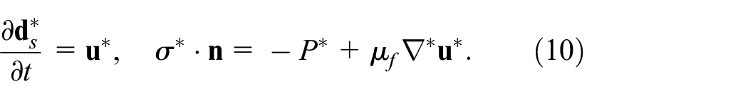
Flexible thin wall deformation is calculated using 42 :

In this context,

where

In the equation earlier, the symbol


In this context, the first and second constants of Lame can be derived using the expressions
The continuity of heat flux and temperatures was used at the thin wall/fluid junction:

in which,
Now, the next set of non-dimensional quantities is invoked:

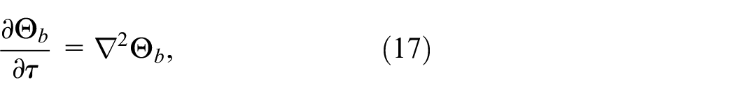
The dimensionless expression of the governing equations was achieved as:


In this context, the thermophysical ratios for thermal diffusivity and density, denoted as
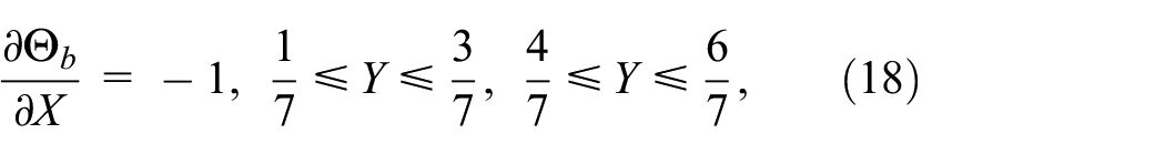
The nondimensional boundary conditions of equations (13)–(16) are:
On the isoflux block:
On the block-fluid interface:

On the flexible wall:

On the top and bottom horizontal walls:

On the left adiabatic wall:

where

The Nusselt number
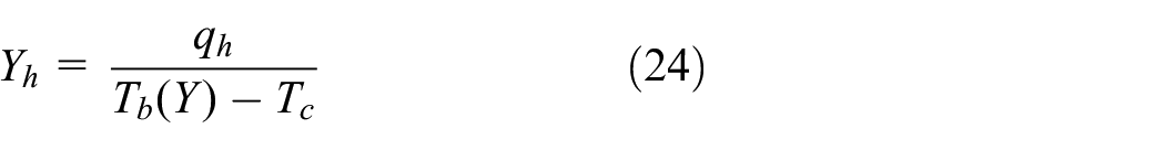
where

By integrating the local heat transfer values, the mean Nusselt number
The above case is for

Previous case for
Computational methodology
The non-dimensional governing equations in equations (13)–(16) subjected to the initial and boundary conditions in equations (18)–(23) are determined numerically by finite element method (FEM) via Comsol. The computational region is discretized toward triangular components that performed in various times as drawn in Figure 2. Features of the finite element method procedure in comsol are explicitly explained by Alhashash and Saleh. 40 In addition, for each of the current variables, the convergence to the solution continues when the relative error satisfies the following condition in each time step:


Grid-points distribution for a mesh size, Extra-Fine with 6369 total elements at different time for
In this study, the crucial selection of an appropriate time step for coupling fluids and structures is automated using a backward differentiation formula (BDF). BDF methods, being implicit numerical integration schemes, employ backward differences for derivative terms, expressing them in relation to previous time steps. The conditionally stable nature of BDF methods imposes restrictions on time step size, requiring a balance between accuracy and computational efficiency. The chosen time step follows a geometric sequence with a ratio of
To assure the robustness of the computational solution and the independence of the mesh size within the computational domain, a series of simulations with different mesh sizes was conducted to evaluate three key parameters, the minimum strength of the flow circulation
Grid sensitivity for

To validate, the streamlines and isotherms were compared against that of Öğüt
43
for the absence of block in the case
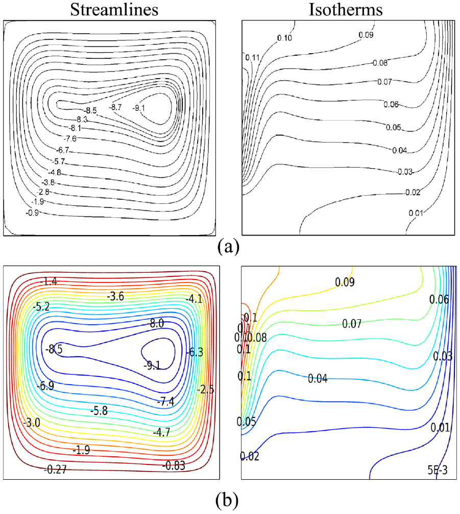
Comparing the streamlines and isotherms obtained from existing literature (a) with the currently calculated streamlines and isotherms (b) excluding the block at

Streamlines (a) and isotherms (b) with the left side showing results from the study by Mehryan et al.
42
and the right side showing results from our current investigation under the conditions of
Results and discussion
The study in this work is carried out toward the following specializing on the linked dimensionless compositions: the number of the heat source,
Figures 5 and 6 present the time evaluation of streamlines and isotherms for the case of

Time dependent of the streamlines at
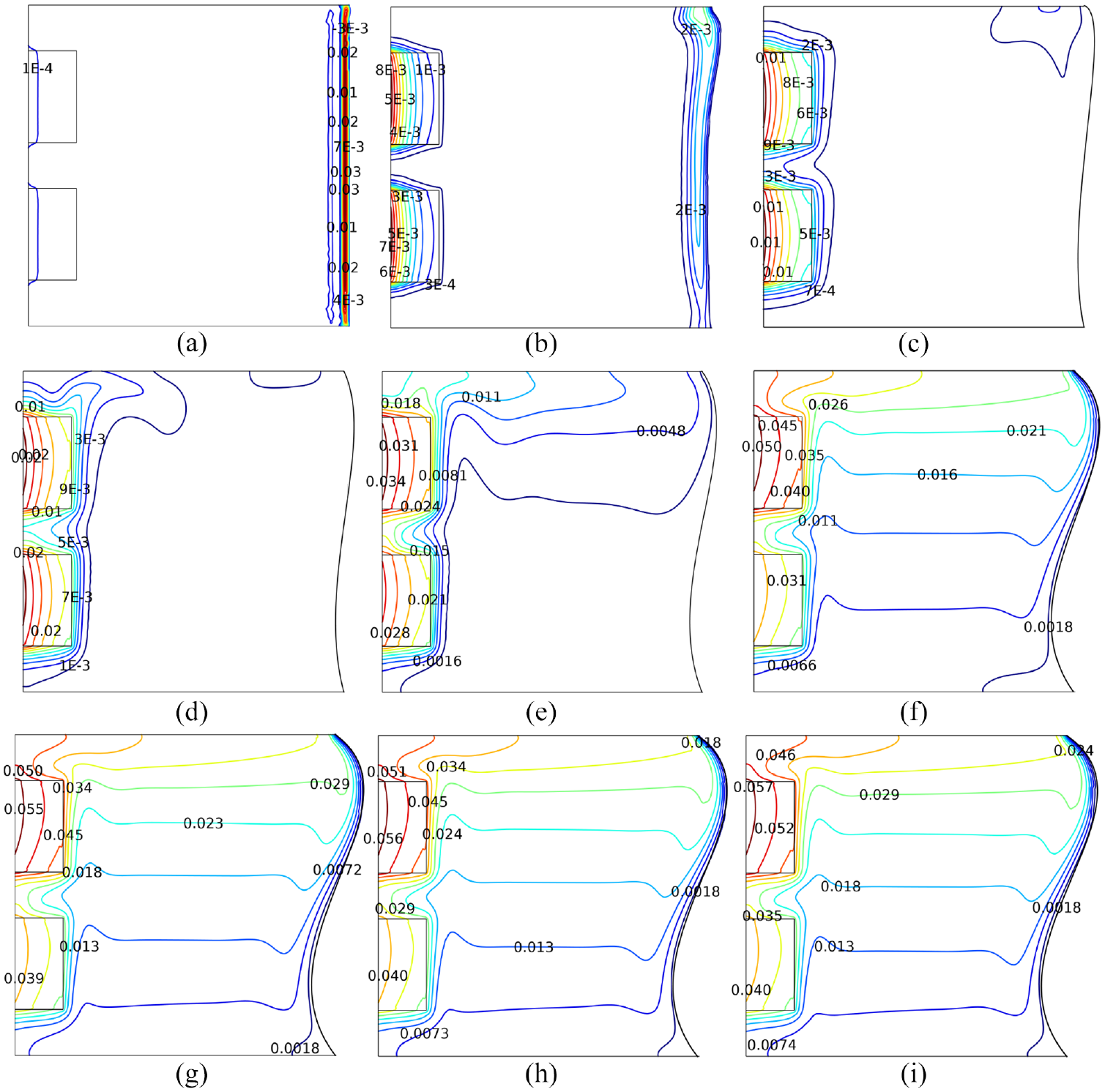
Time dependent of the isotherms at
Figure 7 displays the influence number of the heat source on the streamlines and temperature fields in the enclosures at the steady-state conditions for
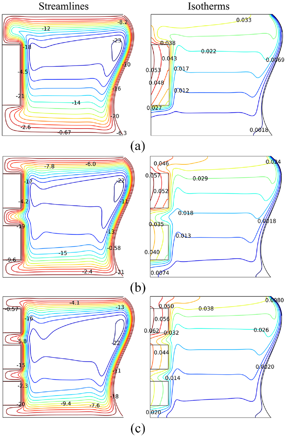
Variety of the streamlines (left) with isotherms (right) by number of the heat source for
Figure 8 shows the impact of the heater thickness on the streamlines and isotherms contours for

Variety of the streamlines (left) with isotherms (right) by heater thickness for
Figure 9 shows the effect of Rayleigh number on the convective flows at the steady-state conditions for
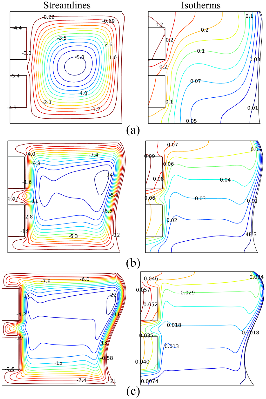
Variety of the streamlines (left) with isotherms (right) by Rayleigh number for
The impact of the number and thickness of the heat source on the left wall temperature are displayed in Figure 10 for

Variation of the left wall temperature at
Figure 11 examines the effect of the Rayleigh number on the average Nusselt number for two samples of

Variation of average
The impact of the arrangement of discrete heater on the average Nusselt number is plotted in Figure 12. In the presence of three heaters, a significant decrease in the mean Nusselt number is observed as the heater thickness increases, possibly due to the increased volume of the heat source. This pronounced decrease may be related to the increased thermal inertia resulting from the thicker heaters. For the

Variation of
Conclusions
The present study scrutinized the fluid structure interaction on conjugate free convection in an enclosure with a flexible right wall and isoflux heaters mounted on the left wall. The partial differential equations of the governing equations are solved numerically by means of the FEM via Comsol. The graphical visualization of computational results displays the convective flow and the heat transfer rate. The arrangement of the discrete heat source and the Rayleigh number were interconnected to the design of streamlines, thermal pattern, and heat transfer forms. The optimal discrete heat source arrangement must follow our results:
The development of convection heat transfer goes through an initial phase, a transition phase, and a steady state phase. Each phase interval is shifted by adjusting the Rayleigh number and arrangement of discrete heat source.
The steady phase of circulation flow formation and thermal pattern are based on the Rayleigh number and arrangement of discrete heater. Multiple discrete heat sources
Thickness and number of heat sources had indistinguishable impact on the appearance of the flexibility shape.
Thicker and higher number of heat source generate higher temperature near the isoflux block, but create a sparser thermal boundary layer.
Increasing the block amplitude by 25% for
Footnotes
Correction (October 2024):
Handling Editor: Chenhui Liang
Declaration of conflicting interests
The author(s) declared no potential conflicts of interest with respect to the research, authorship, and/or publication of this article.
Funding
The author(s) disclosed receipt of the following financial support for the research, authorship, and/or publication of this article: This work is funded by the Deanship of Scientific Research at Jouf University under (Grant No. DGSSR-2023-02-02034).
Data availability
The data that support the result of this study are available upon request from the authors.