
Abstract
The purpose of this study is to explore the characteristics of fluid-structure interaction and heat transfer enhancement from a hot flexible thin plate during mixed convection. The mixed convection condition of the plate heater is assumed by placing it inside a lid driven cavity with top and bottom cavity walls being fixed and insulated while left and right cavity walls maintained at constant low temperature move in downward and upward direction respectively. The Galerkin Finite Element Approach has been used to numerically solve equations describing unsteady flow, thermal and stress fields in the Arbitrary Lagrangian-Eularian (ALE) framework. Key parameters include Reynolds number (Re) and Richardson number (Ri), and Cauchy number (Ca) which are varied in the range of 100 ≤ Re ≤ 500, 0.1 ≤ Ri ≤10, and 10−4 ≤ Ca ≤ 10−7 respectively. To investigate the effect of the heater’s geometry, the plate length (l) has been varied within 0.1 ≤ l ≤ 0.7. The results have been presented in terms of the distribution of streamline and isotherm, heat transfer rate from the flexible heater as well as its deformation. The outcomes reveal that heat transfer enhances with the increase in Reynolds number and Richardson number while it degrades with the extension of the heater. Moreover, thermal frequency obtained by Fast Fourier Transform (FFT) indicates dominant peaks at higher Reynolds number and Richardson number although these become insignificant as the plate becomes rigid.
Keywords
Introduction
A broad spectrum of applications involves convective heat transfer1–3 in cavities, pipes, channels, and other structures. One of the most notable is the utilization of mixed convection in a multitude of thermal engineering applications, such as the cooling of MEMS and electronic devices, furnaces, high-performance building insulation, nuclear reactor multi-shield construction, glass manufacturing, food preparation, photovoltaics, drying systems, chemical manufacturing machinery, and other technologies. In recent years, the study of convective heat transfer in different enclosure systems, namely square cavities, has drawn a lot of interest from the research community. With the advent of modern technologies, scientists have been focused on the augmentation of fluid circulation and subsequent thermal enhancement inside these cavities via different techniques. One such technique is the addition of lid velocities to the cavity walls which imparts additional circulation to the fluid-dynamic forces. Numerous heat transfer engineering applications, including the cooling of electronic equipment, the drying of food, heat exchangers, and nuclear reactors, rely on convection in a lid-driven cavity.4–13 Thus, scientists are ardently working on several active and passive approaches to boost convective heat transfer. An emerging passive technique is regulating the rate of heat transfer by the interaction between fluid and structure, specifically the interplay between fluid velocity and solid distortion, known as fluid-structure interaction (FSI). The following provides a brief summary of recent research regarding the application of FSI14–31 to facilitate heat exchange in various cavity systems under lid-driven conditions.
Modern researchers are becoming increasingly keen on improving thermal performance in various cavity systems or enclosures. Calcagni et al. 1 numerically examined the influence of a discrete bottom-wall mounted heater in a square enclosure on free convective heat transfer. In an attempt to investigate laminar mixed convection in an air-filled square cavity, Hidki et al. 2 observed that the insertion of heating bodies had diverse effects on the convective Nusselt numbers. Thereafter, Jasim et al. 3 explored mixed convective heat exchange in a vented nanofluid-filled cavity comprising an inner rotating cylinder and reported that a counter-clockwise rotation of the cylinder offered improved heat transfer.
Recently cavities driven by lid4–6 have been a topic of great interest among the research community since it introduces another way to achieve thermal enhancement via forced fluid circulation. Sharif 7 examined the laminar mixed convective heat transfer in shallow, rectangular, two-dimensional lid-driven cavities with an aspect ratio of 10. Later, in their study of mixed convection heat transfer in a cavity consisting of an obstacle that is, a circular body, Oztop et al. 8 noticed that the orientation of the moving lid had the most significant effect on flow and thermal fields. Addition of such obstacles have become fairly common as Shi and Khodadadi 9 investigated the heat and flow fields’ periodic states due to a thin, oscillating fin connected to the wall of a cavity driven by a square lid. Moreover, impact on convection heat transfer by inserting obstacles in a triangular lid-driven cavity, 10 a rotating cylinder in a square lid-driven cavity, 11 an ellipse shaped obstacle in a lid-driven trapezoidal cavity 12 and a circular cylinder in a two-sided lid-driven cavity 13 were investigated.
Lately another technique, namely FSI, is on the rise as scientists are seeking for alternative means for controlling the heat transfer associated with cavities via passive approach. Consequently, Küttler and Wall 14 designed a simple and robust FSI solver suitable for a multitude of applications due to higher processing capability. Using this FSI model, Al-Amiri and Khanafer 15 numerically evaluated flow and heat transfer in a lid-driven enclosure with a flexible bottom surface for a variety of parameters. They found that the bottom wall’s flexibility significantly affected its shape and thereby the cavity’s capacity for heat transfer. In addition, they established that mixed convection leads to major deformation of the flexible wall which results in momentum and energy transfer inside the enclosure. Khanafer 16 then modified the shape of the heated bottom wall of the preceding framework by incorporating stiff rectangular and sinusoidal wavy profiles. His findings demonstrated that the flexible wall improved heat transfer more than the stiff wall, especially at higher Grashof numbers. Selimefendigil and Öztop 17 quantitatively investigated MHD (magneto hydro dynamics) mixed convection in a lid-driven chamber composed of an elastic side wall and filled with CuO-nanofluid. When the side wall was relatively flexible, they observed an increase in absolute heat exchange. Later, several types of flexible devices such as flexible wall 18 in a square cavity, one or more oscillating flexible fins19–23 in a square or L-shaped enclosure, a flexible baffle 24 in an air-filled chamber etc. were installed to improve the thermal performance of these systems. Membranes being essential part of many technical equipment including fuel cells and distillation systems were introduced eventually. Jamesahar et al. 25 used a highly conductive membrane diagonally to investigate transient natural convection in a square cavity. They inferred that the stiffness and shape of the membrane marked a significant impact on the convective heat transfer inside the cavity. Following this, Ghalambaz et al. 26 studied a vertically bisected cavity by a thin flexible membrane and heated at a sinusoidal rate. When the effect of an external magnetic field was considered, Mehryan et al. 27 found that the shape of the vertical impermeable membrane and the heat transfer within the cavity were affected substantially by the magnetic field orientation. The flow and rate of heat transfer of a circular cavity comprising distinct cold and hot parts and separated by a flexible partition was investigated by Shahrestani et al. 28
Natural convection induced by a heater inside a square enclosure along with the impact of plate elasticity on heat and fluid transfer had been explored by Hashem Zadeh et al. 29 In order to investigate natural convection heat transfer for a wide range of parameters, Mehryan et al. 30 inspected a 2D square cavity system containing a centrally placed deformable heater. The location of the reference value and the tilt angle of the flexible hot plate have a significant impact on the heat transfer and fluid motion inside the cavity. Afterward, Ghalambaz et al. 31 studied the flow and heat transfer of pseudoplastic and dilatant liquids in a cavity with a thin hot plate. They claimed that increment in heater length resulted in the reduction of average Nusselt number as well as the increase of tensions within the heater.
Though numerous foregoing studies describe the influence of flexible devices and convection with lid-driven systems separately, the combined effects of the fluid-solid coupling between the flexible heater and the mixed convection inside a lid-driven cavity have not been accounted for until now. Hence, the present study aims to explore the impact of mixed convective heat exchange in a square cavity driven by a lid and centrally equipped with a thin flexible heater. The lid walls aid in cooling down the heater rapidly. This investigation can therefore be utilized to model the cooling of flexible electronic devices, flexible industrial machine parts, and different types of fuel rods for a nuclear reactor. In order to fully realize the effect of heater’s deformation, the ALE approach accompanied by Galerkin finite element method32–34 have been integrated in our study. This work clearly focuses on the effects of dynamic flow conditions, flexibility, and heater plate length on improving the system’s ability to transfer heat.
Problem statement and mathematical formulation
Description of physical model
The configuration along with the boundary conditions of the proposed problem are illustrated Figure 1 in a 2D Cartesian coordinate (x*, y*) system. The current setup represents a square cavity of length L* which ranges from (0,0) to (L*, L*). The left wall of the enclosure is moving down, while simultaneously the right wall is moving upwards with a constant lid velocity, uo. A horizontally aligned flexible thin plate heater thickness b* is placed centrally inside the cavity. The flexible plate is presumed to be isotropic and homogeneous with its length varying in the range of 0.1L* ≤ l ≤ 0.7L*. The computational domain consists of water (Pr = 6.2) as the working fluid. The fluid circulates across the domain as a result of the reverse motion of the walls, evolving hydrodynamic forces. Due to its flexibility, the plate is subjected to these dynamic forces and thereby deforms.
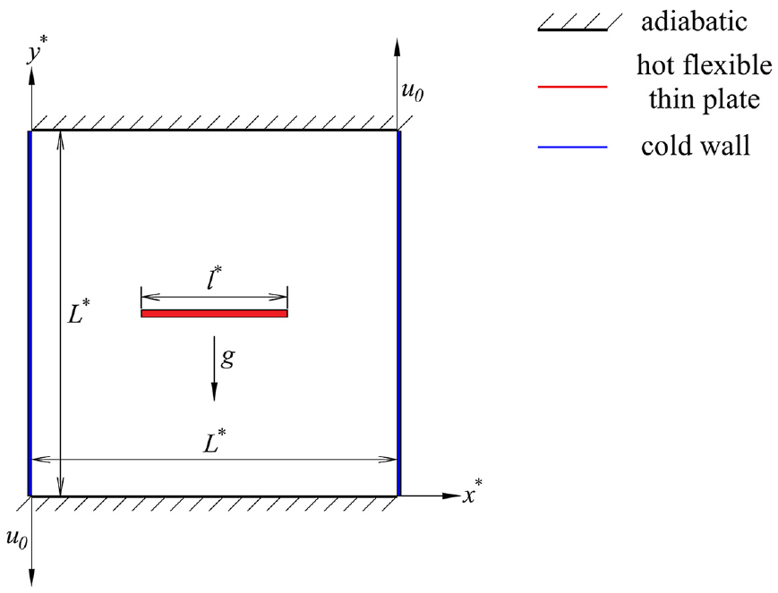
Schematic of the present study (color online).
Governing equations and model assumptions
The fluid flow is assumed to be two-dimensional and laminar, with an isotropic, Newtonian, and incompressible fluid. The cavity is subjected to gravity in the vertical direction while the fluctuations in fluid density is approximated using the Boussinesq approximation. The weight of the plate and the buoyancy force are among the body forces acting on it. Joule heating, viscous dissipation, and radiation effects are ignored. The continuity, momentum, and energy equations governing the fluid dynamics is attributed to mixed convection heat transfer. The well-established framework known as Arbitrary Lagrangian-Eulerian (ALE) approach describes the correlative effects of the fluid and deformable solid element. Implementing the foregoing model assumptions, the dimensional governing equations can be formulated following19,20 as:
Continuity equation:

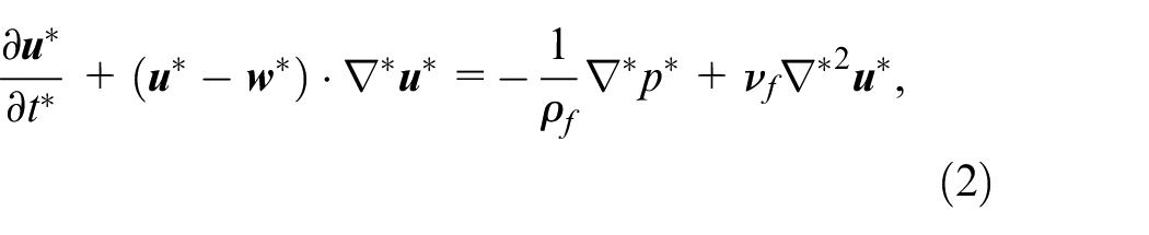
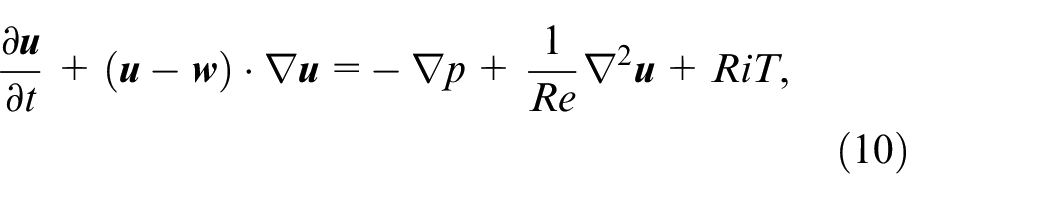
Linear Momentum equation:
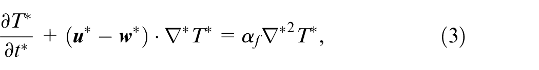
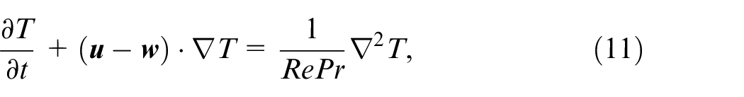
Energy equation:
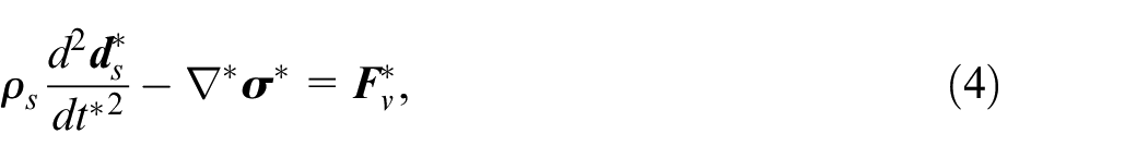
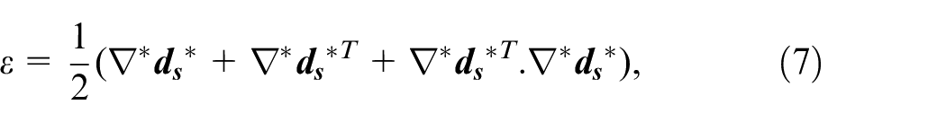
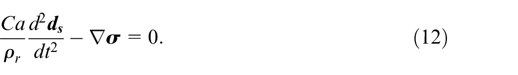
Elasto-dynamic equation to represent the displacement of the plate:
Where
Implementing the Neo-Hookean model, the stress tensor

Where
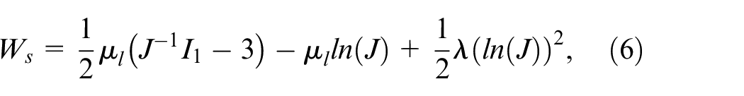
Where μl and λ are Lame’s first and second parameters respectively while I1 is the first variant of Cauchy-green deformation. The following normalizing technique is implemented to obtain the dimensionless forms of their respective dimensional parameters:
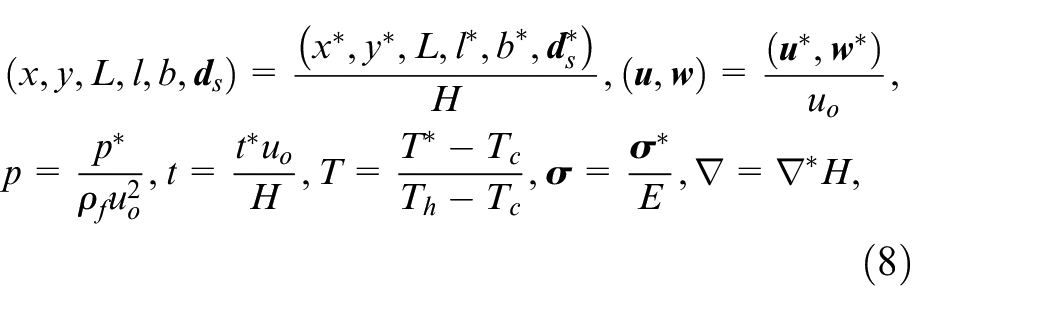
Here, E denotes the modulus of elasticity. It should be emphasized that symbols without superscript “*” represent non-dimensional parameters of the corresponding dimensional ones. Therefore, the dimensional governing equations can be re-written as,
For fluid domain,

For elasto-dynamic domain,
Here, Re = uoH/νf, Pr = νf/αf, Ri = βg(Th–Tc)H/uo2, Ca=ρfuo2/E, and ρ r = ρf/ρs denote the Reynolds number, the Prandtl number, the Richardson number, the Cauchy number, and the density ratio respectively.
System boundary conditions
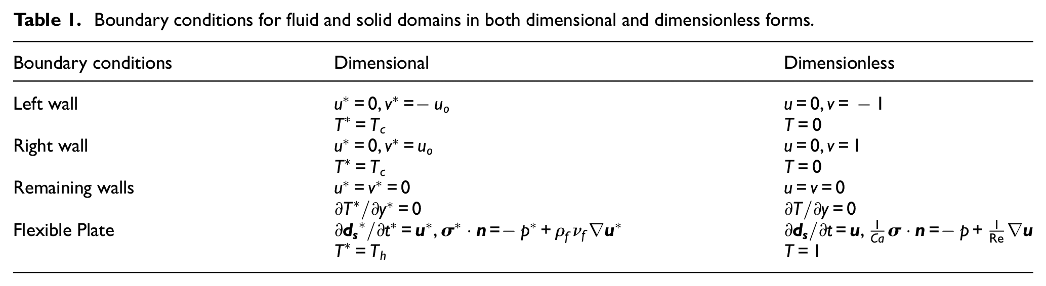
As mentioned earlier, the side walls of the cavity are maintained at constant lid velocity of uo. The remaining walls are at no slip boundary condition of the fluid (u* = 0). The side walls are kept at a cold temperature (Tc*) whereas the top and bottom walls are thermally insulated. Besides, a hot temperature (Th*) is applied to the flexible thin heater inside the cavity. Moreover, the dimensionless initial velocity, pressure and temperature are assumed to be zero. Hence, the dimensional boundary conditions as well as their dimensionless equivalents are tabulated for flow, thermal and displacement fields in Table 1.
Boundary conditions for fluid and solid domains in both dimensional and dimensionless forms.
Performance parameters
The concept of stream function is implemented to delineate the flow field motion within the cavity which can be evaluated as:
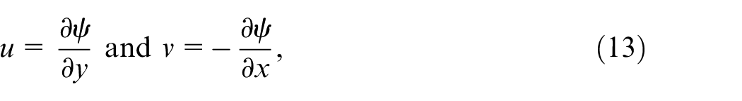
Utilizing these equations, the flow behavior and heat transfer mechanisms inside the cavity can be evaluated.
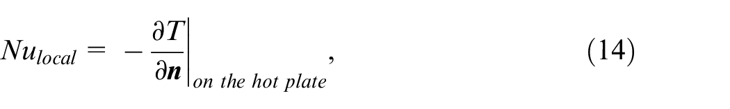
To signify the heat transfer performance of the current system, the Nusselt number have been evaluated in this study. The local Nusselt number along the boundaries of the hot plate can be obtained as:
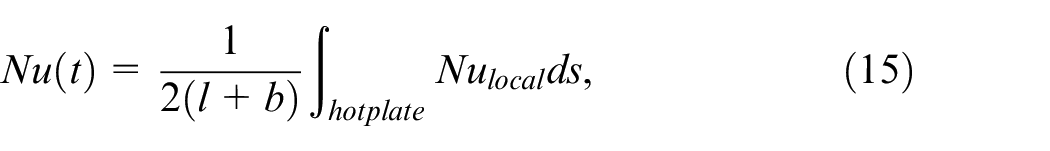
The spatially averaged Nusselt number, thus, is introduced as:
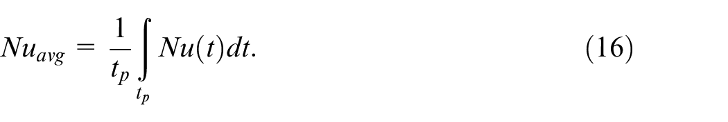
Finally, the time averaged Nusselt number over the time period tp can be evaluated as:
Numerical methodology
Using the commercial finite element-based tool “COMSOL Multiphysics 6.0,” the above-mentioned dimensionless governing equations (9)–(12) along with their corresponding boundary conditions have been numerically solved. The Galerkin finite element approach 32 is employed to model the set of nonlinear partial differential equations. A mesh consisting of non-uniform triangular elements has been utilized to map the computational domain as depicted in Figure 2. The Arbitrary Lagrangian-Eulerian (ALE) technique33,34 is also implemented to accurately represent the deformation of the flexible plate heater by using a shifting boundary condition in the mesh. This method allows for movement while retaining the fixed domain and shifting the boundary domain. In order to solve the residual discretized equations for each time step the Newton-Raphson method is employed. The numerical solution is considered to have converged when the relative error for each time step is less than or equal 10−4 using the following criterion:
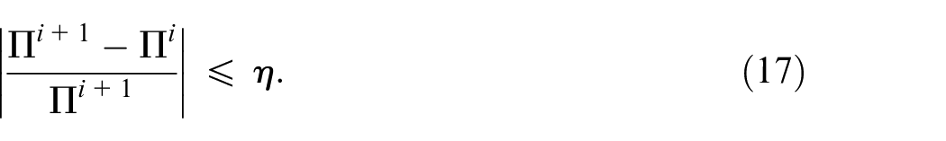
where Π denotes the system variables (velocity, temperature, and pressure) and i expresses the iteration number. Lastly, it is vital to choose the right time step because of the interaction between fluid and structure. Throughout this study, the time step is automatically controlled via a free time step backward differentiation technique. 35
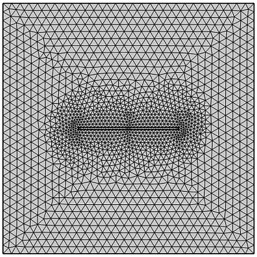
Mesh distribution within the computational domain.
Grid independence test
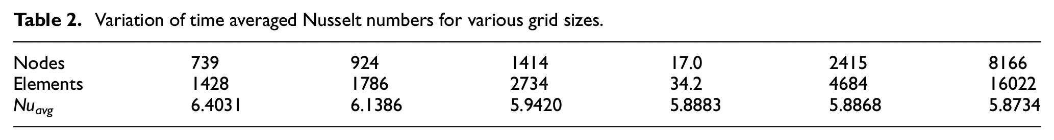
For any computational task, an optimal balance between numerical precision and associated computational cost is required. As a result, an optimal grid distribution with acceptable precision and the shortest processing time has been investigated. Numerous simulations have been conducted by keeping the parameters fixed at Ri = 1, Re = 100, Ca = 10−5, and l = 0.4 while the grid cases have been varied based upon nodes and elements. The time averaged Nusselt number has been computed for these grid cases and the summary of the findings are outlined in Table 2. Therefore, by taking into account the computing time and accuracy, a mesh comprising of 3442 domain elements and 1780 nodes has been selected as the preferred grid setup throughout the study.
Variation of time averaged Nusselt numbers for various grid sizes.
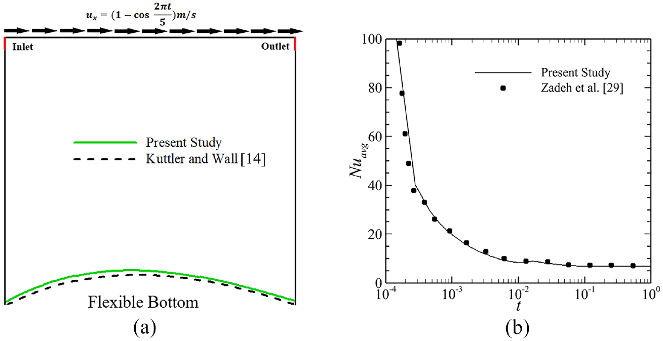
Model validation
The current model is validated using the strategy implemented by Küttler and Wall 14 for fixed-point fluid-structure coupling solvers with dynamic relaxation. From Figure 3(a) a good agreement can be deduced between the current work and that of Küttler and Wall. 14 Figure 3(b) illustrates how the current FSI model is compared to hot flexible thin plate scenario of Hashem Zadeh et al. 29 in terms of average surface Nusselt number. The fluctuation of the average Nusselt number generated by the current framework is quite consistent with that of Hashem Zadeh et al. 29
Results and discussions
In this section, a detailed analysis of the multiple factors that influence fluid flow and the thermal field is presented. The investigation is done for various parameters such as Reynolds number (100 ≤ Re ≤ 500), Richardson numbers (0.1 ≤ Ri ≤ 10), Cauchy numbers (10−4 ≤ Ca ≤ 10−7), and plate length (0.1 ≤ l ≤ 0.7). Other parameters such as the Prandtl number (Pr = 6.2, representing water), non-dimensional body force (Fv = 0), the thickness of the plate (tp = 0.01), the elevation of the heater from the center of the cavity (H = 0), and the density ratio of solid to liquid (ρr = 1) are kept fixed throughout the study. Considering the present problem is inherently unsteady, it is conducive to compute the transient behavior of the flow and temperature fields to assess whether they attain a sustainable profile over time. Thermal frequency of the flow field has been evaluated by performing power spectrum analysis of Nu(t) with the aid of Fast Fourier Transform (FFT). The evolution of the fluid field, on the other hand, has been studied by investigating the streamlines, isotherms, and the shape of the plate heater. Since the system reaches steady state condition for all of the cases after 60 s, as shown in Figure 4, all the outcomes have been presented at t > 60.
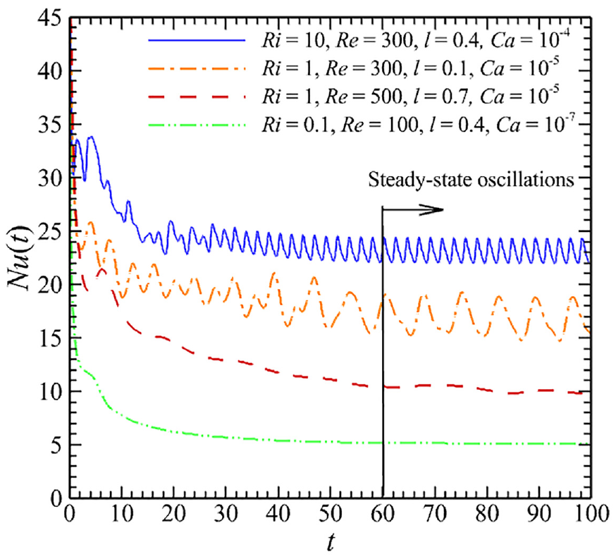
Temporal variation of spatially average Nusselt number for several combinations of governing parameters. (Color online).
Effects of Richardson and Reynolds numbers
In this section Richardson and Reynolds numbers have been varied to investigate effect of buoyancy force and inertia force on flow and thermal field. Streamlines and isotherms of the system at various Richardson numbers and Reynolds numbers have been illustrated in Figures 5 and 6 respectively where Ca = 10−5 and l = 0.4 are kept fixed. When Ri = 0.1, the flow field is dominated by the velocity of the lid rather than the buoyancy force and forced convective heat transfer is observed. Therefore, the counterclockwise motion of the lids induces corresponding counterclockwise vortices. Two diagonally symmetric smaller vortices are developed adjacent to the plate to at Re = 100. As Re is raised to 300 and then eventually to 500, the vortices grow in size, while moving toward center of the plate. Since flow field is equally influenced by the motion of the lid and buoyancy force, mixed convective heat transfer becomes prominent at Ri = 1. However, two vortices are formed for this case too, but one is comparatively bigger. Also, the vortices get bigger with increasing Re. Natural convection emerges as Ri is increased to 10. Due to the higher influence of buoyancy force larger vortices are observed. For Re = 100, a larger vortex is observed at the left side of the cavity, but two comparatively smaller vortices are formed at the right side. Since the lid on the right side is moving in reverse direction to the buoyancy flow, the vortex induced by buoyancy is split into two sub-vortices. One of these two sub-vortices is rotating in a clockwise direction by complying with the buoyancy flow. And the other in counterclockwise direction, as induced by the lid. However, some weaker vortices are also observed at the bottom of the plate. In addition, slight bending of the flexible plate can also be noticed. As Re increases further, primary vortices get more distorted and form more sub-vortices within the flow field. From the plot of isotherms in Figure 6, it can be detected that for a particular Re, the isotherms get more concentrated around the plate with increasing value of Ri. The presence of a cluster of isotherms adjacent to the plate implies a steeper temperature gradient, which results in higher heat transfer. Meanwhile, for a fixed Ri, with higher value of Re, concentration of isotherms increases in the vicinity of the plate and thus heat transfer enhances.
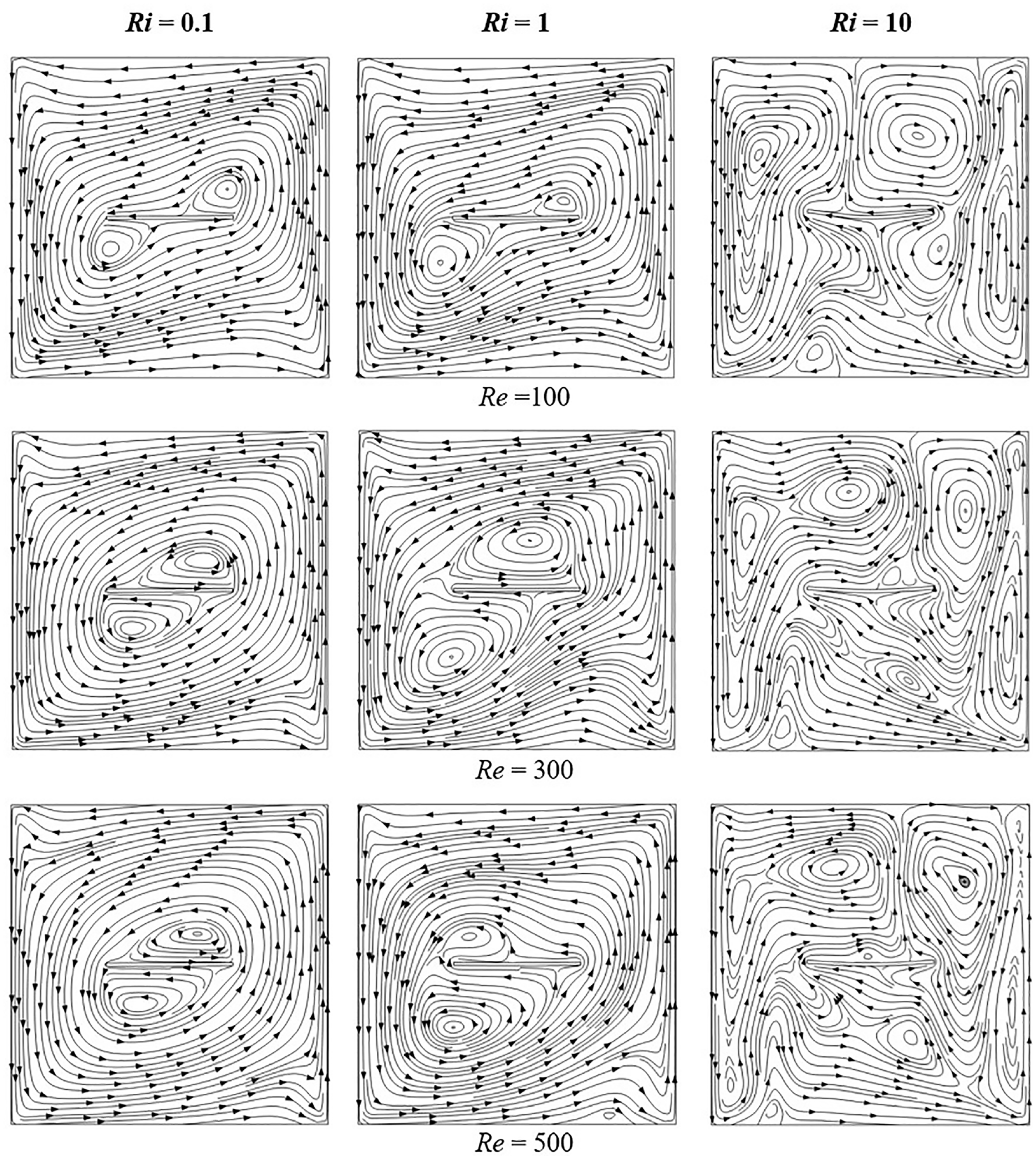
Streamlines at various Reynolds number and Richardson number at Ca = 10−5 and l = 0.4.
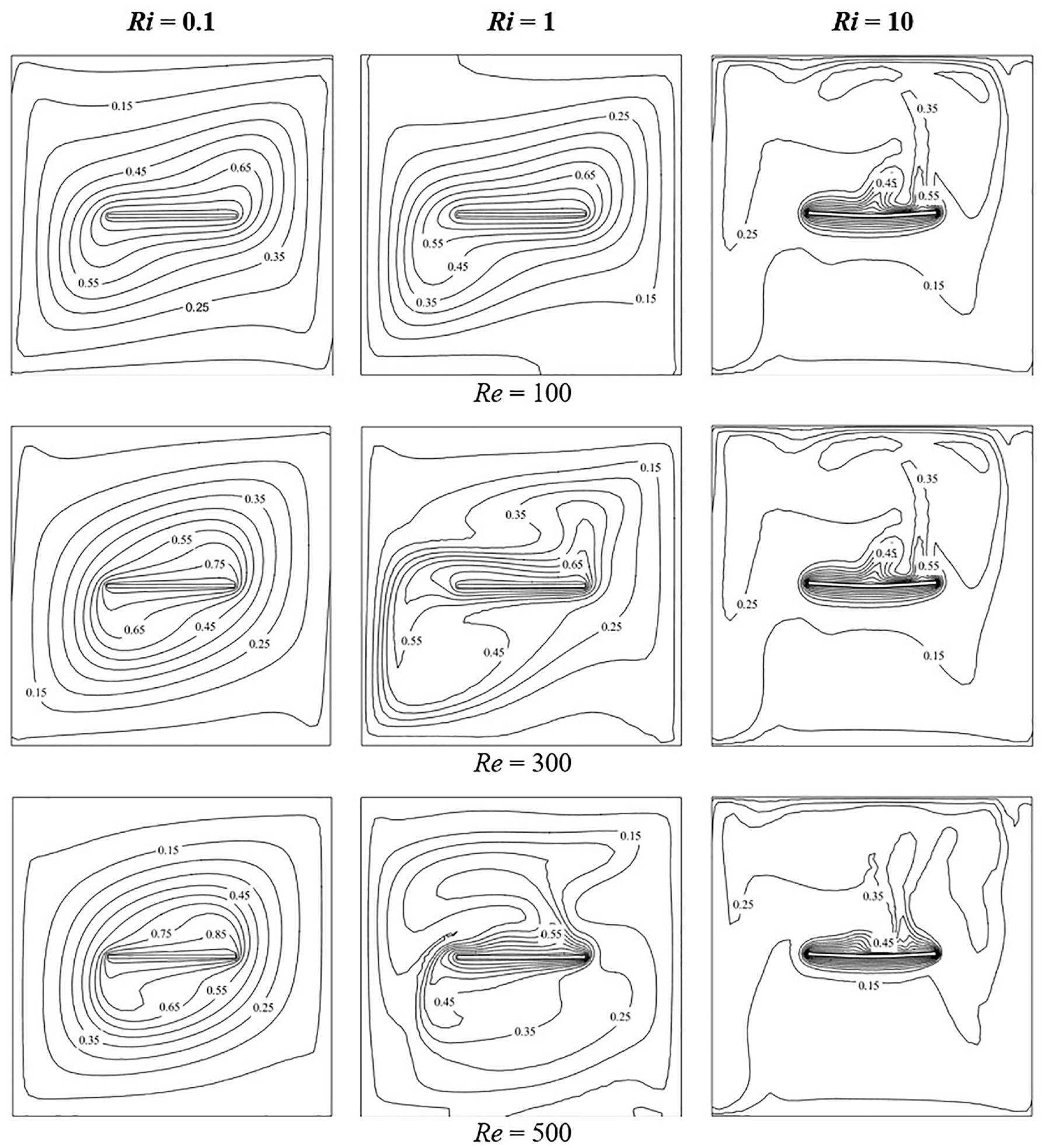
Isotherms at various Reynolds number and Richardson number at Ca = 10−5 and l = 0.4.
Temporal variation of Nu(t) and corresponding power spectrum analysis have been portrayed in Figures 7 and 8 at Re = 300 and Re = 500 respectively for various Richardson numbers. The value of Nu(t) as well as its frequency of oscillation rises up as the value of Ri gets higher, since the effect of buoyancy force becomes dominant. Steeper temperature gradient is observed at higher value of Ri. As for Re = 300, the mean value of Nu(t) increases up to 66% as Ri increases from 0.1 to 1.0 and it enhances by almost 80% when Ri becomes 10. However, in the case of Re = 500, Nu(t) improves by about 100% when Ri goes from 0.1 to 1.0 and then rises by another 90% at Ri = 10. In order to interpret the frequency of the thermal field, power spectrum analysis has been performed for each case by utilizing Fast Fourier Transform (FFT). As depicted, for Ri = 0.1 there is no visible peak in the justifying the lack of fluctuation in the thermal field. For Ri = 1.0, a primary dominant frequency is visible in the plot and the peak that is observed at Re = 500 is comparatively higher than that of Re = 300. At Ri = 10, although some secondary and tertiary peaks are discernible for Re = 300, there is only a single distinguishable peak noticed in case of Re = 500. For further investigation of the thermal frequency, temporal variation of Nu(t) and their respective FFTs have been shown in Figure 9 where Re has been varied by keeping Ri fixed at 10. The value of Nu(t) enhances by about 64% as Re is raised from 100 to 300 and it improves further by around 28% when Re becomes 500. As for the frequency of thermal oscillation, it can be seen that, with increasing value of Re the frequency increases simultaneously. There is no visible peak in the FFT plot of Re = 100 due to the absence of fluctuations. However, two distinct peaks are observed in the case of Re = 300 but there is one discernible peak for Re = 500.
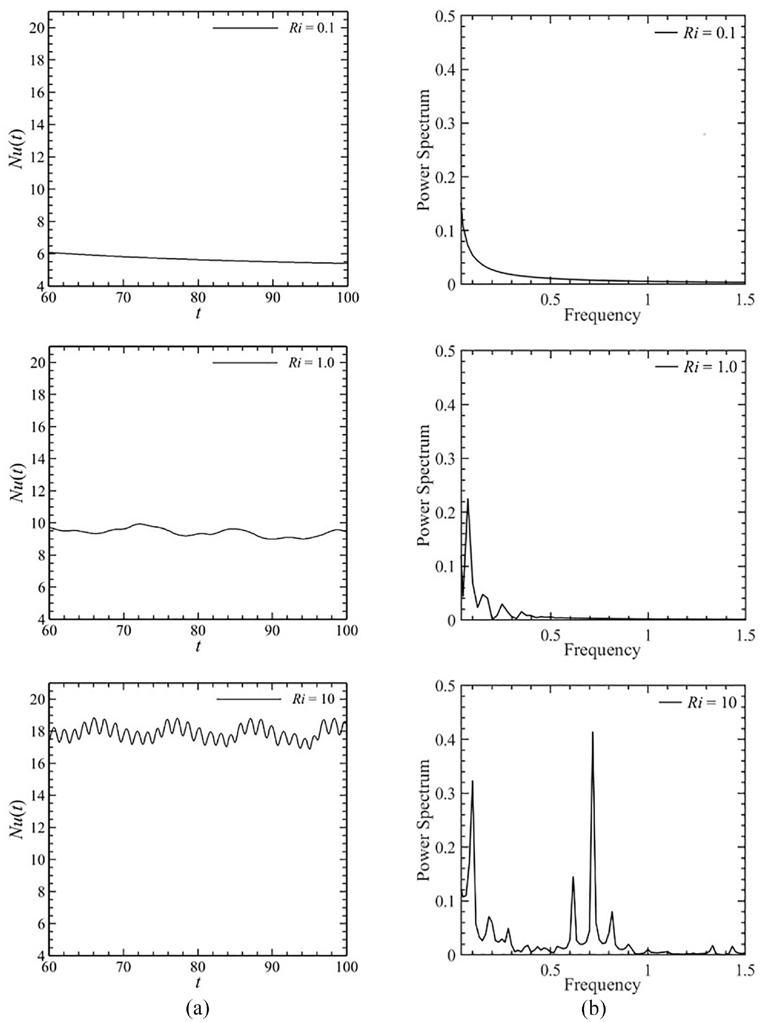
Effect of Richardson number variation on (a) spatially averaged Nusselt number and (b) corresponding FFT for Re = 300, Ca = 10−5 and l = 0.4.
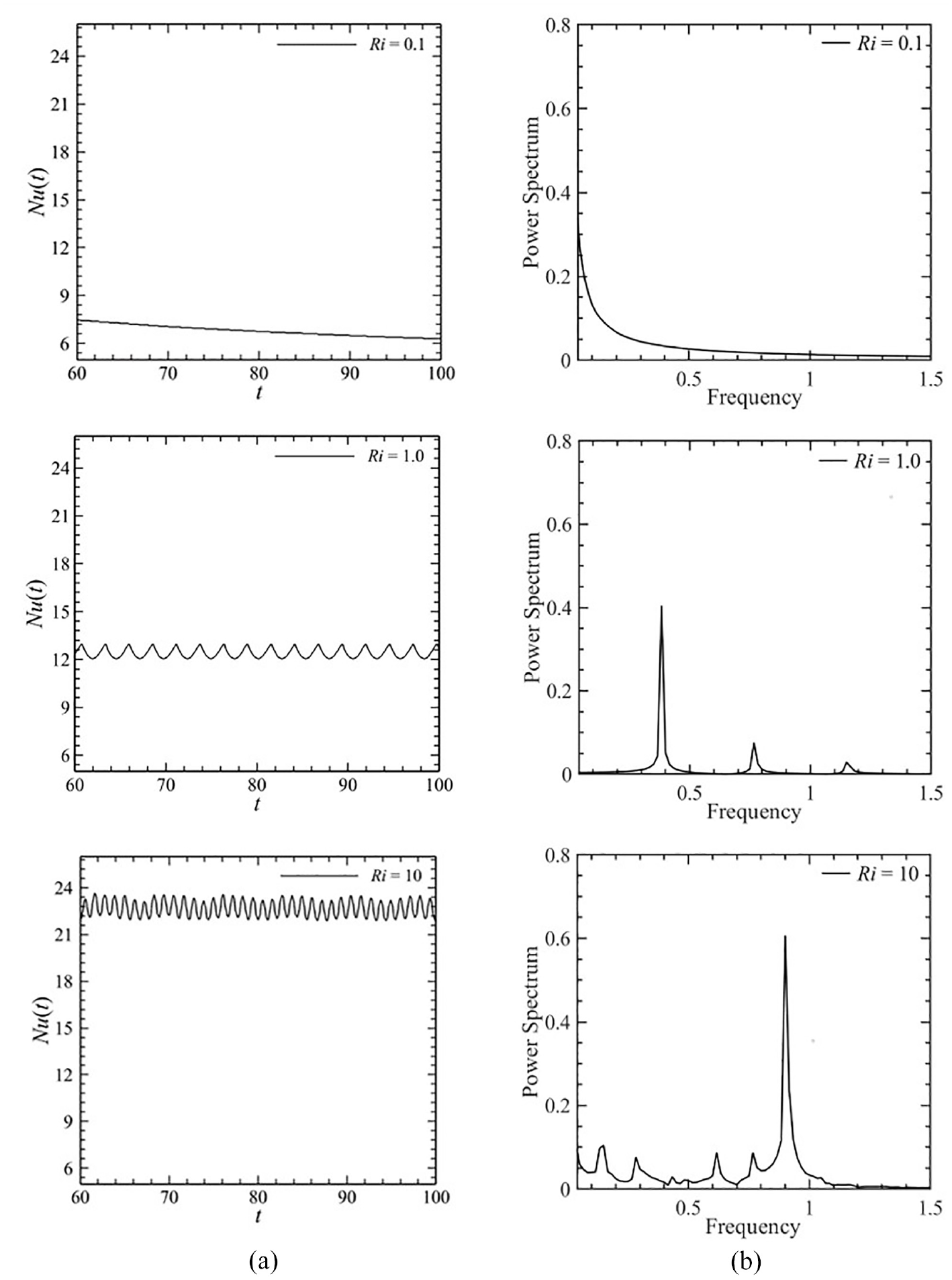
Effect of Richardson number variation on (a) spatially averaged Nusselt number and (b) corresponding FFT for Re = 500, Ca = 10−5 and l = 0.4.
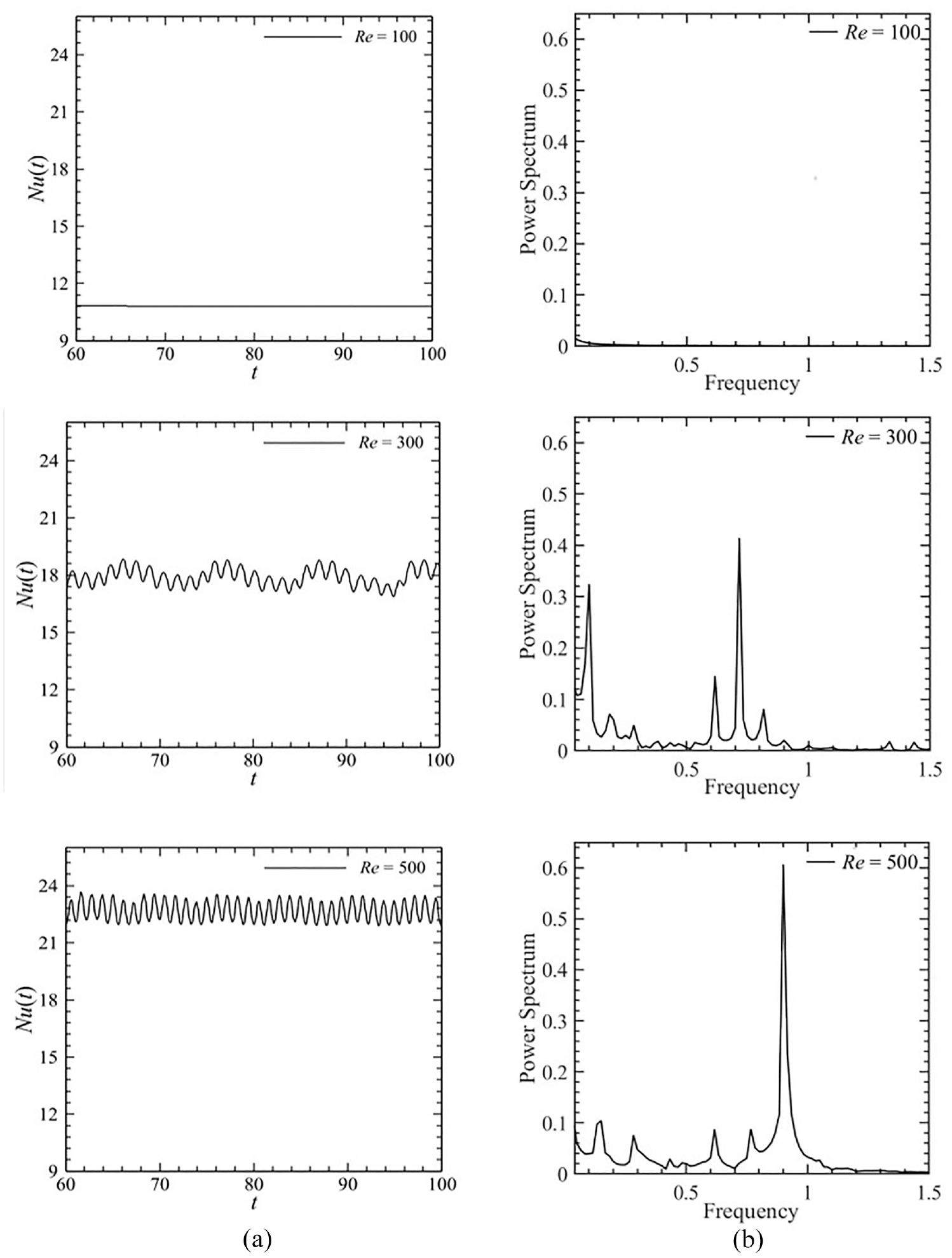
Effect of Reynolds number variation on (a) spatially averaged Nusselt number and (b) corresponding FFT for Ri = 10, Ca = 10−5 and l = 0.4.
Impact of heater length variation
Influence of the heater length on vorticity generation and heat transfer has been examined in this section. Figure 10 shows impact of length of the flexible plate on the flow fields and thermal fields of the cavity for Ri = 1, Ca = 10−5, and Re = 300. The buoyancy-driven flow inside the enclosure gets more obstructed as the plate gets longer, which weakens the flow field. There is no separate vortex zone observed in Figure 10(a) when the length of the flexible heater is 0.1. Fluid can flow freely without encountering many impediments. The fluid flows in an anti-clockwise manner as the side walls are propelled by the lid at the same speed in the opposite direction. When the plate length increases to 0.4, the cavity is partially divided into two regions. As a result, two vortices are formed near the heated flexible plate region, as depicted in Figure 10(b). One is lying above the plate and the other underneath it. As a result, the fluid adjacent to the plate surface has little possibility of moving any further. Therefore, preventing the hot fluid from being transported leading to the reduction of the amount of heat transfer. From Figure 10(c), it can be noticed that the vortices get bigger when the plate is extended to l = 0.7, almost dividing the larger cavity into two smaller ones, and thereby inhibiting the convective heat transfer more. The corresponding isothermal plots also portrays lower concentration of temperature contours near the plate as the plate length increases. Thus, heat transfer reduces as the plate extends more. Moreover, since longer plate is subjected to greater hydro-dynamic force, it bends in concave upward direction.
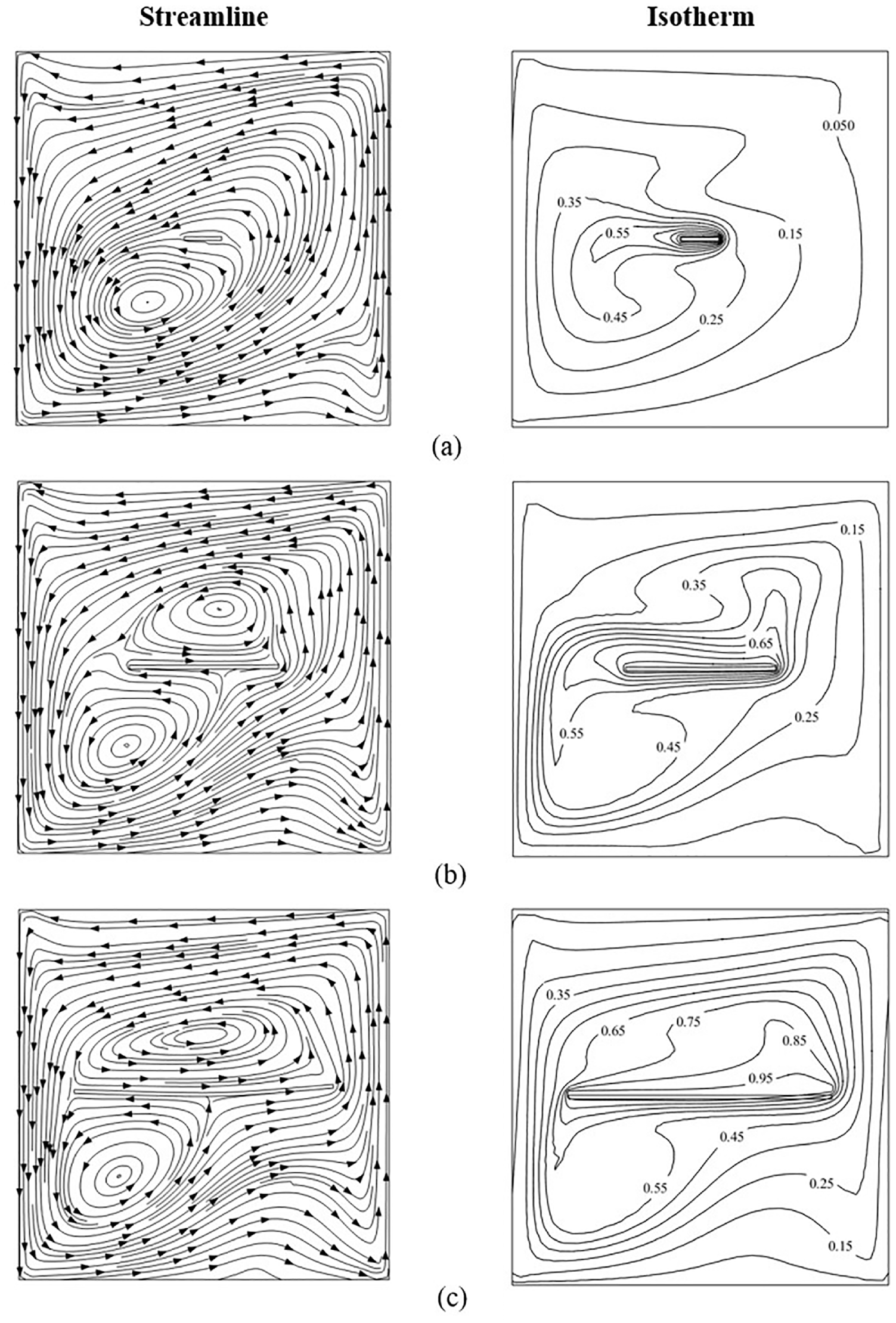
Streamlines and Isotherms at various plate lengths for Ri = 1, Re = 300 and Ca = 10−5: (a) l = 0.1, (b) l = 0.4, and (c) l = 0.7.
The influence of plate length on the spatially averaged Nusselt number and the associated FFTs has been illustrated in Figure 11. The Nu(t) increases as plate length decreases, attaining its maximum value at l = 0.1. Since the presence of a longer plate in the cavity’s midsection generates additional blockage and slows the flow, reducing heat transfer by convection. However, the thermal fluctuations become more prominent as plate length decreases, with the amplitude of the fluctuation being highest at the shortest plate length. When the plate length is 0.4, the Nusselt number drops by 50% and further 25% when the plate length is increased to 0.7. The power spectrum analysis of Nu(t) for various plate lengths has been shown on the right side of Figure 11. At l = 0.1, two distinctive peaks are observed in corresponding FFT plot. As the length extends to 0.4 the fluctuation of Nu(t) diminishes and only a single peak is barely visible in the respective FFT. However, there is no visible peak for l = 0.7 since Nu(t) is not fluctuating in nature for longer plate.
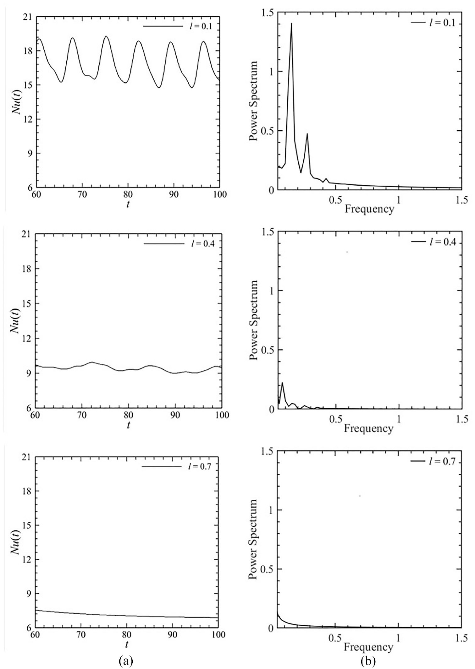
Effect of plate length variation on (a) spatially averaged Nusselt number and (b) corresponding FFT for Re = 300, Ri = 1.0, and Ca = 10−5.
Impact of flexibility of heater
In this section impact of flexibility of heater on flow and thermal field has been analyzed. To investigate the influence of the heater plate’s flexibility, different Cauchy numbers are inspected at various Re for Ri = 1 and Ri = 10 while the plate length is kept constant at l = 0.4. The effect of flexibility can be clearly depicted from Figures 12 and 13 respectively. As Cauchy number is the reciprocal of the material’s elastic modulus, lowering its value increases the plate’s elasticity modulus, resulting in a stiffer plate. On the other hand, a higher Cauchy number implies a lower elasticity modulus, which means a more flexible plate.
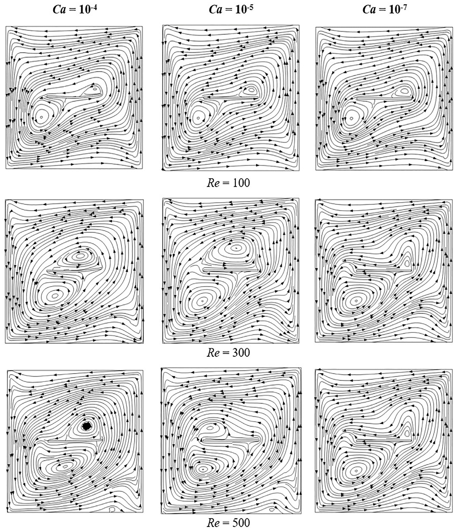
Streamlines at various Cauchy number and Reynolds number at Ri = 1, l = 0.4.
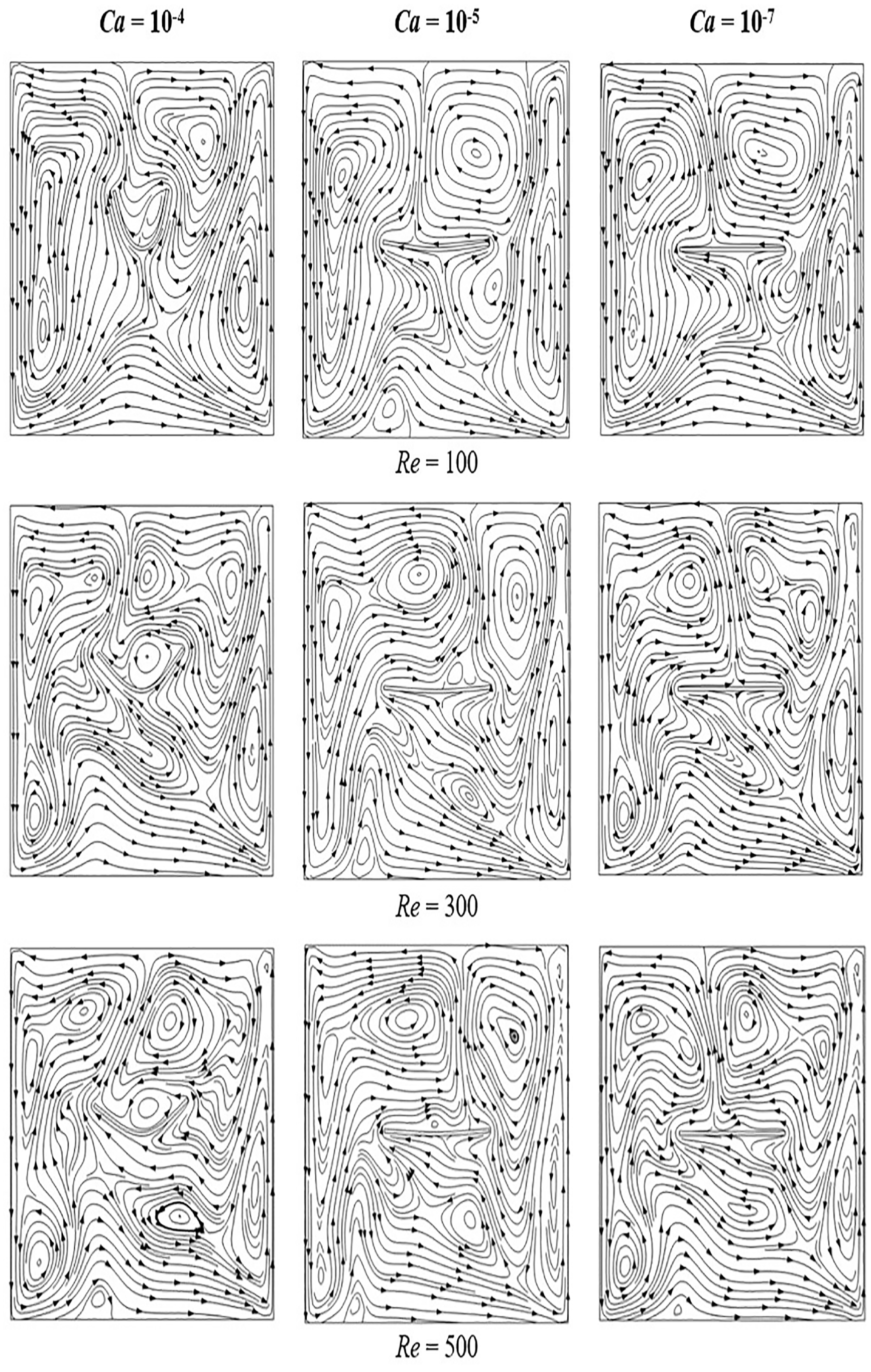
Streamlines at various Cauchy number and Reynolds number at Ri = 10, l = 0.4.
At Ri = 1, two counterclockwise vortices can be seen in the flow field of Figure 12, one at the top of the plate and the other at the bottom. The plate slightly bends at Ca = 10−4 and the bending diminishes as Re rises from 100 to 500. This is because as the dynamic force gets stronger, the vortex under the plate gets bigger, which impedes the deformation of the plate. However, the geometry of the plate is unaffected by fluid-structure interaction at Cauchy number of 10−5 and 10−7 due to the increased stiffness of the plate. As compared to the relatively smooth and streamlined flow field that has been observed at Ri = 1, a very chaotic and irregular flow field can be noticed for Ri = 10 in Figure 13. Since at Ri = 10, natural convection dominates the flow pattern. Due to the increased influence of buoyancy the plate bends significantly in concave upward direction at Ca = 10−4 and there is also slight bending when Ca = 10−5. However, the plate gets straighter when the Re increases. Because with the increase of dynamic force the effect of buoyancy force gets balanced out. As for flexibility of Ca = 10−7, the plate is still unaffected by the flow field as the plate is very much rigid.
Temporal variation of Nu(t) and corresponding FFTs have been presented in Figures 14 and 15 at Re = 300 for Richardson number 1.0 and 10 respectively. The plot of Nu(t) at Ri = 0.1 has been omitted since the variation of Nusselt number with Ca is negligible when Ri = 0.1. For Ri = 1.0 heat transfer enhances by around 22% as the value of Ca increases from 10−5 to 10−4. However, there is no significant variation in heat transfer between the cases of Ca = 10−5 and 10−7 since at lower value of Ca the plate is almost unaffected by the flow field. Nu(t) shows a highly fluctuating nature when Ca = 10−4, hence a relatively higher peak is visible in corresponding FFT. On the other hand, the fluctuating nature of Nu(t) at Ca = 10−5 and 10−7 is quite similar. Moreover, the frequency of fluctuation is also reduced, therefore, relatively shorter peaks are noticed as compared to Ca = 10−4 in respective FFTs. When Ri = 10 there is also no increase of heat transfer as Ca increases from 10−7 to 10−5. However, Nu(t) improves by about 28% when value of Ca further rises to 10−4. The fluctuation of Nu(t) is free from instabilities when Ca = 10−4 and hence single primary peak can be observed in the FFT. On the other hand, in case of Ca = 10−5 the secondary peak is also discernible along with the primary one and for Ca = 10−7 there is no peak due to the absence of fluctuation in Nu(t) plot.
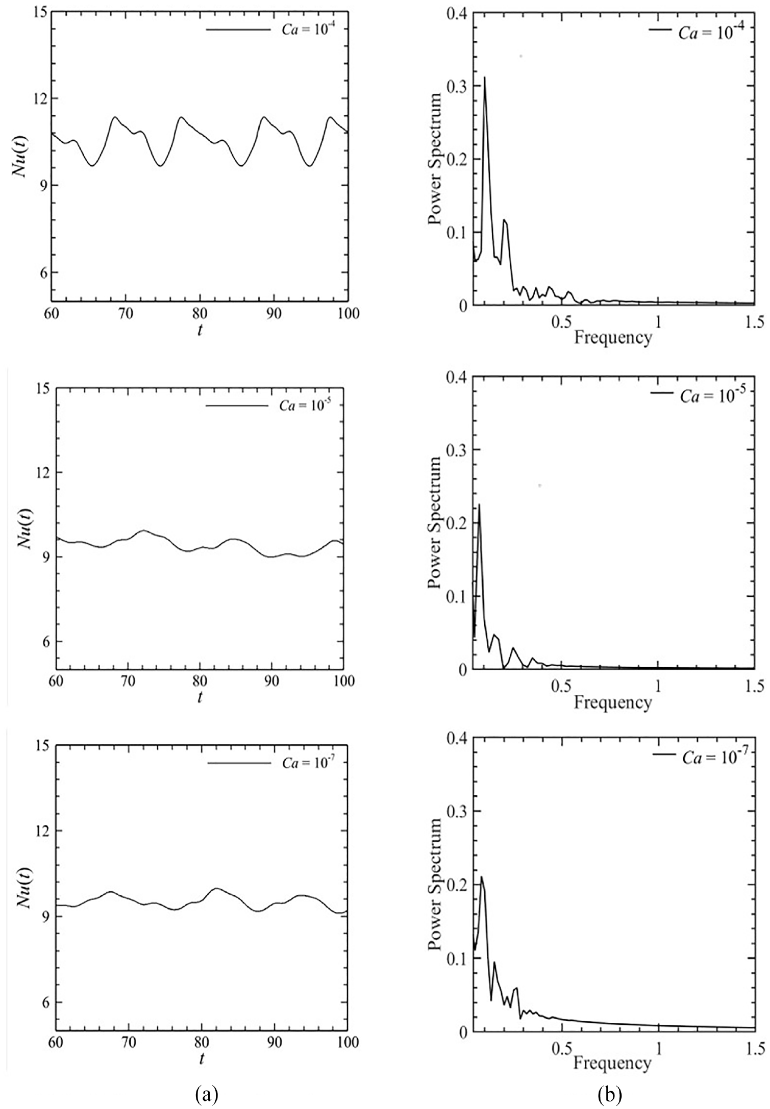
Effect of Elasticity variation on (a) spatially averaged Nusselt number and (b) corresponding FFT for Re = 300 and Ri = 1.0.
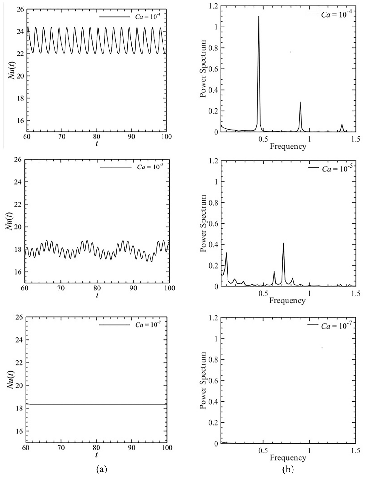
Effect of Elasticity variation on (a) spatially averaged Nusselt number and (b) corresponding FFT for Re = 300 and Ri = 10.
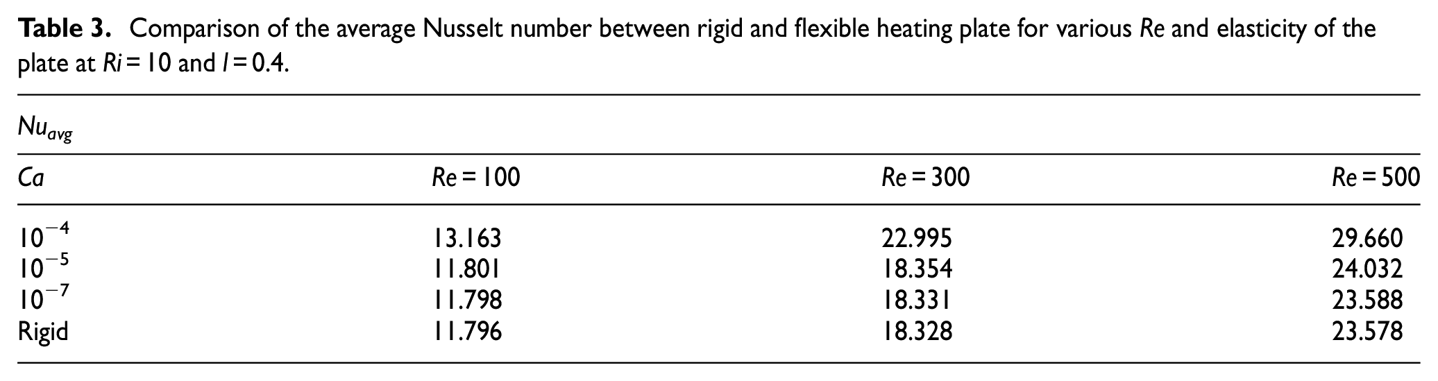
Figure 16 portrays the variation of time averaged Nusselt number with Re for different values of Ca and Ri. In Figure 16(a) there is visibly no variation of Nuavg with Re as well as Ca when Ri = 0.1. However, there is a variation observed in Figure 16(b), but only in case of Re = 300 and Ca = 10−4. As depicted in Figure 16(c) the variation increases with the increasing value of Re for Ri = 10. This variation of Nuavg as the flexible plate becomes rigid has been shown in Table 3. From the value of Nuavg listed in Table 3 it can be clearly observed that maximum heat transfer is achieved when the plate is most flexible, and the Reynolds number is the highest.
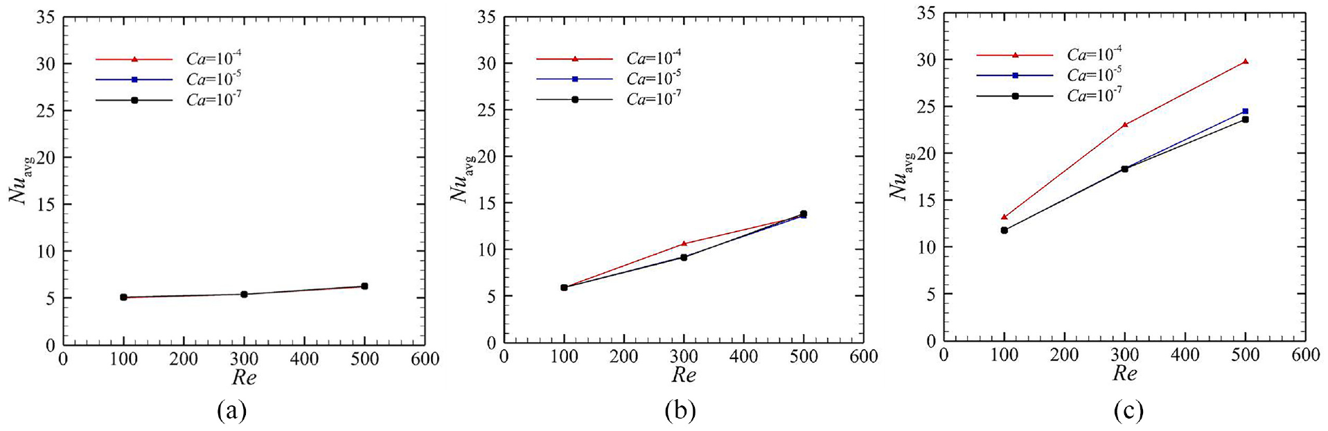
Variation of time averaged Nusselt Number with Reynolds number at various Cauchy number and at l = 0.4: (a) Ri = 0.1, (b) Ri = 1, and (c) Ri = 10.
Comparison of the average Nusselt number between rigid and flexible heating plate for various Re and elasticity of the plate at Ri = 10 and l = 0.4.
Conclusions
The current study focuses on heat transfer from a flexible heater inside a lid-driven cavity numerically. Galerkin finite element method has been incorporated to discretize the domain. Additionally, for the moving domain the Arbitrary Lagrangian-Eulerian method is employed. Impact of Reynolds and Richardson number, flexibility of heater as well as its length have been thoroughly explored. Following remarks can be drawn from this investigation:
Highest heat transfer is observed when Reynolds and Richardson number is maximum. However, the flexible heater deforms more at lower Reynolds number and higher Richardson number.
As the length of the heater increases it undergoes more deformation and heat transfer is impeded substantially.
Effect of flexibility of heater on heat transfer is negligible at lower Richardson number. At higher Richardson number heat transfer enhances as the heater becomes more flexible.
Thermal frequency becomes more prominent as the Reynolds number and Richardson number increases. However, the frequency diminishes as the plate becomes longer and more rigid.
Footnotes
Appendix
Acknowledgements
Authors sincerely acknowledge the Basic Research Grant: Grant No.: 5336(100)-Sl. 23; Dated: June 30, 2021; provided by Bangladesh University of Engineering and Technology (BUET). Authors also appreciate CFDHT Research Group, Department of Mechanical Engineering-BUET, for thoughtful discussions and support in conducting the research.
Declaration of conflicting interests
The author(s) declared no potential conflicts of interest with respect to the research, authorship, and/or publication of this article.
Funding
Authors sincerely acknowledge the Basic Research Grant: Grant No.: 5336(100)-Sl. 23; Dated: June 30, 2021; provided by Bangladesh University of Engineering and Technology (BUET).