
Abstract
Dynamic model of the ball in space for ball screw mechanism is established under different angular accelerations of the screw, and non-linear equations of the ball acceleration motion model were solved in accordance with ball movement characteristics during acceleration process of the ball screw mechanism. Forces and motion on the ball were analyzed taking into consideration acceleration state and the characteristics of the ball. Using the existing structural parameters of the ball screw mechanism and accelerating operating conditions of the ball, motion parameters of the ball were theoretically analyzed using simulations at different angular accelerations of the screw, along with motion parameters of the ball, which included contact angle, helix angle, the ball center locus helix path radius, normal force at contact points of the ball, the tangential velocity of ball center, relative sliding velocity of ball, and drag torque of the ball screw mechanism. A ball screw comprehensive test bench was used to experimentally measure drag torque of the ball screw mechanism under different angular accelerations of the screw. Changing regularity was found to be consistent between measured data with simulation results. As a result, acceleration dynamic model of the ball in space was demonstrated to be accurate and feasible.
Introduction
As a key component of numerical control machine tool, performance of the ball screw mechanism (BSM) has significant impact on processing quality of the workplaces. Additionally, state of accelerated motion between the ball and raceways for a BSM has been found to have significant influence on BSM performance. Running status is restricted to BSM drag torque, contact angle between balls and raceways, and movement characteristics of the ball. Previous research on BSM has focused on contact status and relative motion track between the ball and raceways. Birger and Arutunyan 1 and Lin and colleagues2–4 concluded that there was a nearly linear relationship between the spin angle velocity and rotational angular velocity of the balls and the rotational speed of the screw. Tsai et al. 5 studied a technique that can determine the onset of preload loss in a ball screw feed drive system via monitoring the change of ball pass frequency. The ball pass frequency of a ball screw with preload is smaller than that without preload due to the friction force caused by the preload. Li et al. 6 established the model of the dynamic contact angle of BSM combined with the geometric parameters of the ball and the raceway between nut and screw. They verified that the inner contact angles in screw raceway are always greater than the external angles in nut raceway under high-speed working conditions. Wei et al. 7 established a wear model that predicts the decrease in the preload and applied it to the wear estimation of the offset preloaded BSM. The model can effectively analyze the variation in the preload with the axial wear depth of the contact areas in different running strokes, rotational speeds, and ellipse ratios. They confirmed that the variations of these two contact angles with the axial load are strongly related to the critical load. Miyaguchi et al. 8 proposed that after the change of the motion direction of the nut, the drag torque of the double nuts ball screw will generate dynamic diversity and the transmitted torque is becoming smaller than which is in the steady state. Xu et al. 9 established creep analysis model more accurately to calculate the friction of a ball screw. Through the creep analysis and the influence of the creep parameters on the ball screw friction and friction distribution will be discussed. Zhou et al.10,11 found that the error between the calculated preload using the traditional formula and measured value was significantly large. They determined total drag torque of the BSM due to friction between the ball and nut raceway, along with a linear correlation between preload and drag torque for the preloaded BSM. However, they did not study the accelerated motion characteristics of the BSM. It is important to note that research into accelerated motion characteristic for a BSM would be beneficial in improving the service lifetime and transmission precision of the BSM. 12 Mu and Feng considered the centrifugal force and gyroscopic moment acting on the ball screw, and the dynamic model of high-speed ball screw was set up. They proposed that the effects of different working conditions, such as the running speed and the axial preload, affect the dynamic characteristic of ball screw at high speed which is greatly different from that of ball screw at low speed. 13 In the above cases, the motion rules of the ball were explored when the BSM is under a uniform motion and quasistatic state. However, there are unbalanced force and inadequate lubrication at two contact points of the ball of BSM in the acceleration process. The characteristics of acceleration motion and mechanical characteristics of balls of the ball screw are studied; the wear can be reduced, service life can be extended, and the transmission accuracy can be improved in the ball screw in the accelerated motion.
In this article, a dynamic model of the ball undergoing accelerated motion of the BSM in space is proposed. This model is based on the ball relative motion rule. Numerical differentiation and Newton–Raphson methods were used to solve the non-linear equations. Dynamic model of the ball in space was simulated, which allowed the changing regularity contact angle, helix angle, the ball center locus helix path radius, tangential velocity of the ball center, relative sliding velocity of the ball, and drag torque of the BSM to be obtained under different angular accelerations of the screw. Drag torque of the BSM at different screw angular accelerations were obtained experimentally using the BSM comprehensive test bench. This allowed both accuracy and feasibility of the dynamic model of the ball to be verified.
Theoretical analysis
Contact angle of BSM
In order to facilitate the systematic study of the kinematic rules of the ball, the Cartesian coordinate

Coordinates of ball screws.
The contact angle of the BSM is useful to determine relative positional relationship between the ball and raceway, along with kinematic relationship between the screw, ball, and nut. Position vectors for contact point A between the ball and screw raceway and contact point B between the ball and nut raceway (Figure 2) were defined using the Frenet–Serret coordinate system


where

Contact angle.
As shown in Figure 2,
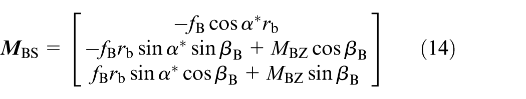
Position matrix of contact points A and B on the ball in the coordinates system
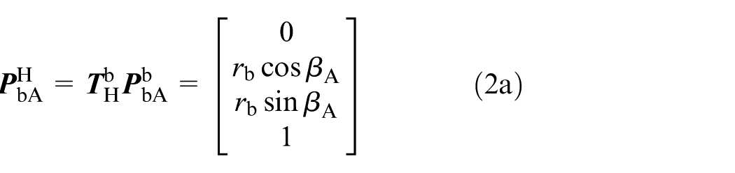

where
Ball contact point kinematics
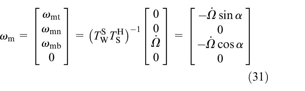
Assume that acceleration of the ball center relative to the screw in the direction tangential to the helix path is
where
Slide-roll mixed motion at contact point A and pure rolling at contact point B on the ball exists during the accelerated motion of the screw. If relative motion between the ball and raceway of the nut is pure rolling, namely, relative sliding velocity at the contact point B is zero, then
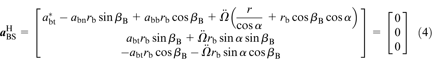
where
Since spinning angular acceleration of point B between the ball and nut raceway is zero, the following equation can be obtained

From equation (4), rotation angular acceleration of the ball around the axis t can be expressed as

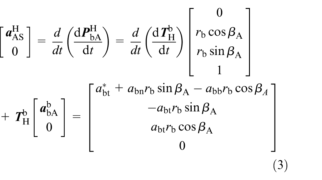
Then, relative sliding acceleration of the ball in the coordinates system
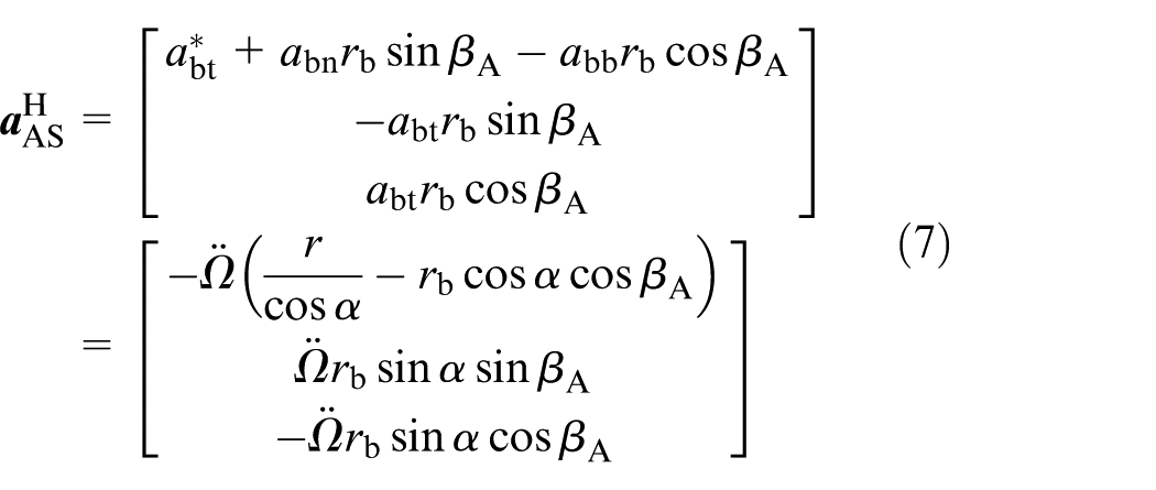
Based on relative acceleration of the ball (equation (4)), relative acceleration of point A in the ball, relative to screw raceway in tangential direction t can be expressed as
Assuming

Based on equations (5)–(8), the following equations can be obtained


Dynamics analysis of ball contact points
When the ball screw is accelerated, it is affected by positive pressure from the raceways friction along the contact area, inertia force, oil film resistance, drag torque, inertia moment, and gyroscopic moment. The balanced force and moment equations acting on the ball in the coordinate system


where
Friction force at contact point B can be split into two components. Friction

where
Substituting equations (13) and (14) into equations (11) and (12), force and force moment balance equations of the ball can be obtained

In equation (15),
According to the relationship between total preload of BSM and contact pressure of the ball in the normal direction, pressure at contact point B in the normal direction can be obtained as

where
Non-linear equations can be solved using the Newton–Raphson method. Then, contact angles

where
Flowchart of numerical analyses
The flowchart exhibited in Figure 3 is presented to illustrate how all parameters in non-linear equations related to the roll-slide behavior of a ball screw are obtained in sequence by numerical analyses from the satisfaction of the convergence criterion. The specification of the BSM and the running conditions are shown in Table 1; the simulation can be obtained. By simulation of the dynamic model of the ball, the changing regularity of running parameters of the BSM can be obtained under the different angular accelerations of the screw.
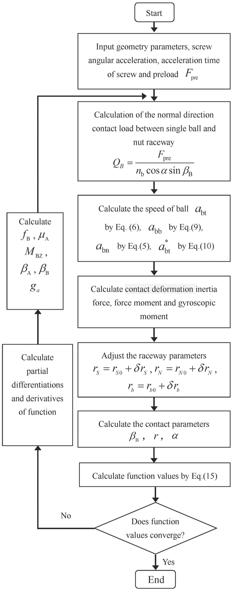
Flowchart for the computation of mechanical model of the BSM.
Ball screw parameters and running conditions.
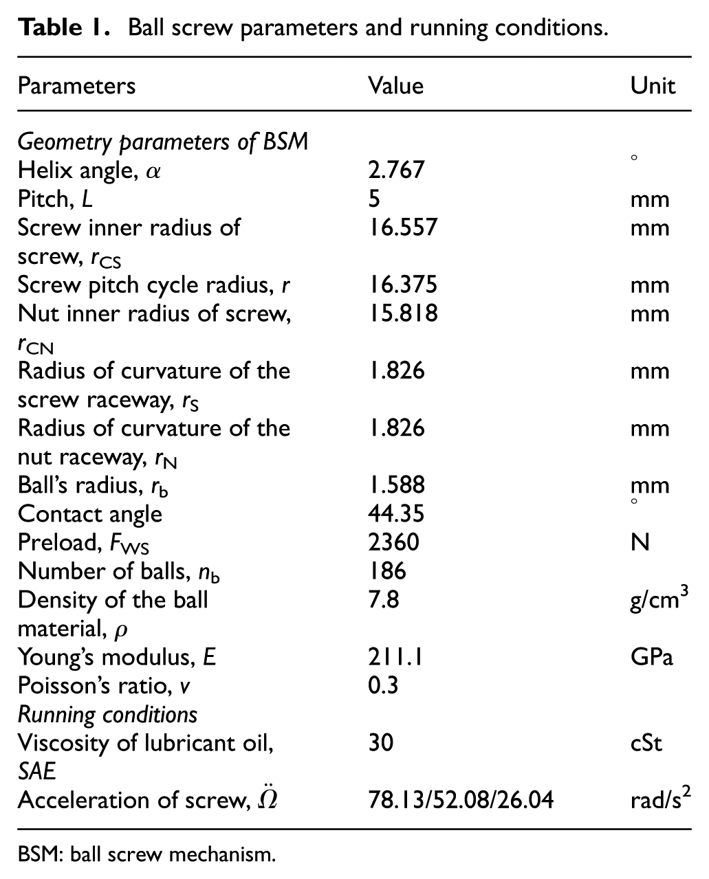
BSM: ball screw mechanism.
Contact stress
Curvature of the ball was approximated to an ellipse and is define as

Ball contact with the screw raceway can be expressed as

Ball contact with the nut raceway can be expressed as
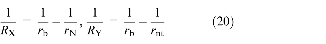
where
According to the Hertz contact theory, 17 boundary curve of the ball and raceway contact area can be expressed as
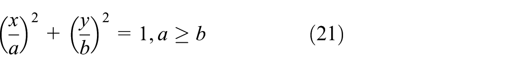
where a is elliptical long axle and b is elliptical short axle.
A method of using standard elliptic integral was proposed by Thomas and Hoersch. 18 Parameters of ball and raceway contact ellipse can be expressed as
where
where
Effective elastic modulus between two contact surfaces can be expressed as

where
Normal elasticity approximation can be expressed as

Relationship between normal load
where
Torsional slip friction force
Initial value for relative rigid displacement of contact bodies

and
where
Rigid displacement is expressed as equation (26), and normal stress is calculated by Hertz contact theory. The shear stress is solved as follows 19

where
So, torsional moment and rigid angle of the ball between the ball and raceway can be expressed as


where G is the shear modulus.
Gyroscopic moment
When screw angular velocity is
where
Gyroscopic moment of the ball during accelerated motion can be expressed as

where
Then, rotation angular velocity of the ball in the coordinate system

Inertia force, inertia moment
When the screw accelerates, inertial force and moment of the ball can be decomposed into two components. Inertial force and moment of the ball are caused due to acceleration of the ball. This acceleration motion of the ball is caused by the screw friction force and angular velocity of the ball.
Inertial force and inertial moment due to acceleration
Sliding acceleration of contact point A on the ball in the coordinate system

Acceleration of contact point A on the ball is equal to acceleration at contact point A on the screw minus the sliding acceleration at contact point A on the ball. Acceleration of contact point A on the ball can be expressed as follows

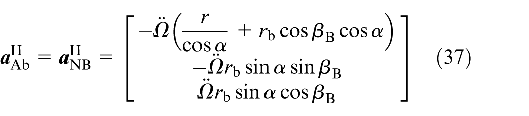
Acceleration of point A on the screw can be obtained as follows

Equation (37) is satisfied when there is pure rolling at contact point B between the ball and nut raceway. This results in velocity of point B on the nut relative to point B on the screw to be equal to acceleration at contact point A on the ball
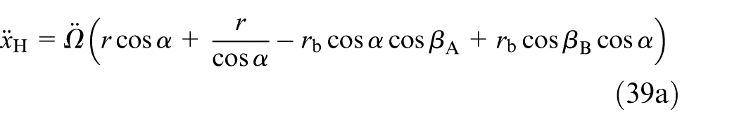
By substituting equations (36) and (37) into equation (35), acceleration at contact point A on the ball can be expressed as follows

In the coordinate system


The inertial force caused acceleration through integral method to point in the coordinate system


By substituting equation (39) into equation (40), inertia force of the ball can be obtained as

In the coordinate system
where
According to the integral method, inertia moment of ball in the coordinate system

Inertia force and inertia moment due to angular velocity
Referring to the study of Wei et al., 3 when the screw accelerates, the inertia force which caused the angular velocity of the ball through integral method to any point in the ball can be obtained as


Inertial force of the whole ball in the inertial coordinate system


where
In the coordinate system

Then, according to the integral method of the inertia moment, inertia moment of ball in the coordinate system

Then, total inertial force and moment of the ball during acceleration in the coordinate system


Sliding friction and friction torque of the ball
Contact area of the ball and the screw raceways is defined as

where
Total frictional force on the contact area

When macro sliding occurs at the point A, total friction moment of the corresponding contact area can be expressed as

Experimental details
In order to verify the dynamic model of the ball in space subjected to varying angular acceleration of the screw, a test bench for BSM was set up to conduct test. A three-dimensional (3D) schematic along with the experimental setup of the test bench is shown in Figure 4. This test bench can be designed in accordance with actual working conditions. The experimental setup of this test bench has two nuts—the first nut to work, and the second nut to move with the operation platform when the screw is working. However, when the functions are reversed, that is, for the second nut to work and the first nut to move with the operation platform during drag torque test of the BSM, and the #30 lubricating oil was used to lubricate, the drag torque can be obtained at different angular accelerations. During the test, force measurements are made using a tension–compression sensor, and drag torque of BSM can be calculated by the product of the force multiplied by the arm of force.

The BSM test bench.
Results and discussion
Drag torque of ball screw
Variation of the drag torque as a function of screw speed is shown in Figure 5. It can be observed that drag torque is increased with increase in the screw’s rotational velocity. Additionally, a larger angular acceleration of the screw resulted in greater friction torque of the BSM. The ball need to overcome friction force to drive nut acceleration as acceleration of the screw is increased.

Variation of drag torque.
Changing regularity of the drag torque is demonstrated to be consistent between measured and simulated BSM data at varying angular acceleration of the screw. According to the dynamic model, angular acceleration was adjusted; however, drag torque of simulation can be compared with measured value.
Contact angles at screw
and nut
Variation of contact angle as a function of screw speed is shown in Figure 6. It can be seen that contact angle formed at the screw and nut is different. This difference is further increased with increase in angular acceleration of the screw. In general, contact angle formed at the screw is larger than that formed at the nut. Along with increasing speed of the screw, under same preload of the BSM, contact angle formed at the screw was increased, whereas contact angle formed at the nut decreased with increase in speed of the screw. Increase in speed results in the centrifugal force affecting the contact angle at the nut to decrease in magnitude. Difference between contact angle at the screw and nut increases with increase in angular acceleration of the screw.

Variation of contact angle.
Helix angle
Different angular accelerations of the screw generate different helix angles for the BSM, even under similar running conditions. When values for the angular accelerations are substituted into initial helix angle and pitch parameters in Table 1, helix angles under the different running conditions were obtained as shown in Figure 7. Under similar running conditions, helix angle formed at lower angular acceleration always has a higher magnitude compared to larger angular acceleration. Speed and the angular acceleration of BSM are two factors that influence helix angle. In the case, where BSM speed was increased, the ball is far away from the screw axis due to the centrifugal force. This resulted in a significantly reduced helix angle at larger angular accelerations.

Helix angle.
Radius of the helix trajectory at the ball center
Different angular accelerations of the screw generate different radius of the helix trajectory at the BSM ball center, in spite of similar running conditions being maintained (Figure 8). Under similar running conditions, radius of helix trajectory at the ball center always results in a higher angular acceleration in comparison to small angular acceleration. Speed and angular acceleration of BSM are two factors that influence radius of the helix trajectory at the ball center. In the case, where BSM speed was increased, the ball was far away from the screw axis due to the centrifugal force, which results in a significantly larger radius of the helix trajectory at the ball center.

Radius of the helix trajectory at the ball center.
Normal force of the ball contact points
Different angular accelerations of the screw generate different normal force at contact points of the ball, in spite of similar running conditions being maintained as shown in Figure 9. In general, normal force formed at contact point A is larger than that formed at contact point B. Along with increasing speed of the screw, under same preload of the BSM, normal force formed at contact point A was decreased, whereas normal force formed at contact point B was caused by the centrifugal force. At the same time, normal force at contact points of the ball always results in a higher angular acceleration in comparison to small angular acceleration due to the inertia force. Speed and angular acceleration of BSM are two factors that influence normal force at contact points of the ball.

Normal force of the ball contact points.
Motion relation of the ball contact points
As shown in Figures 10 and 11, under similar running conditions, tangential velocity of the ball center and relative slide velocity between the ball and screw at larger angular acceleration of the screw are always the obvious change than at smaller angular acceleration. Collision force between the ball and raceways is increased due to speed and angular acceleration of the screw and causes the relative slide velocity between the ball and screw, and tangential velocity of the ball center to change.
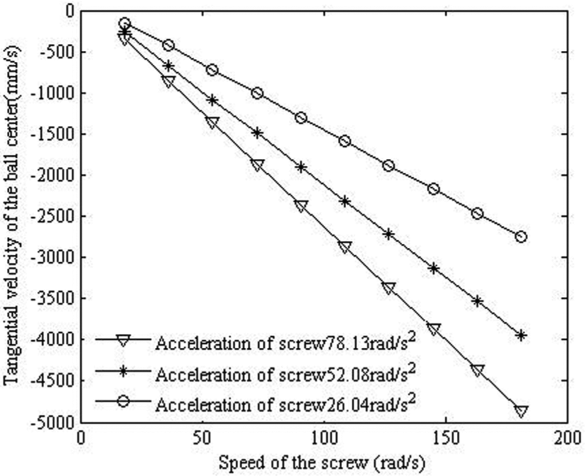
Linear velocity of the ball center with respect to the raceway of the screw.

Relative sliding velocity of the ball.
Friction coefficient
Different speeds of the screw generate different friction coefficients of the BSM on the same running conditions. As shown in Figure 12, the friction coefficient increases with the increase of the speed of the BSM. When the screw angular speed is small, the inertia force of the ball is smaller, and the impact force of the ball in the raceway is smaller, and the friction coefficient value is less. However, the friction coefficient increases as the speed of the BSM is larger, due to the ball appearing collision force between the ball and raceways, and it caused contact surface of the ball is larger. However it caused friction coefficient value becoming larger, with the greater angular acceleration of the screw, the larger inertial force that caused by the balls, and it caused contact surface of the ball and screw raceway becoming larger.

Friction coefficient.
Conclusion
Drag torque was found to increase across the whole test stage, and larger angular acceleration of the screw resulted in significant change in drag torque of the BSM. Comparison of simulation and experimental results revealed that the changing regularity of the drag torque was consistent when the screw angular velocity is not more than 1800 r/min. Thus, it can be concluded that dynamic model of the ball in space was accurate and feasible.
Increase in velocity and angular acceleration of BSM resulted in a variable tendency of the contact angle, that is, contact angle formed at the screw was different from that at the nut. Contact angle formed at the screw and at the nut exhibited non-linear behavior.
Under similar conditions, helix angle formed at large angular acceleration of the screw and higher speeds of screw were always higher compared to smaller angular acceleration of the screw and lower speed. By increasing speed of BSM, helix angle can be significantly reduced.
Radius of the helix trajectory at the BSM ball center was likely to be affected by speed and angular acceleration of the screw. Reducing speed or angular acceleration of the screw improved radius of the helix trajectory at the BSM ball center.
Speed and angular acceleration of BSM are two factors that influence normal force at contact points of the ball.
Footnotes
Acknowledgements
The authors are grateful to other participants of the projects for their cooperation.
Handling Editor: Davood Younesian
Declaration of conflicting interests
The author(s) declared no potential conflicts of interest with respect to the research, authorship, and/or publication of this article.
Funding
The author(s) disclosed receipt of the following financial support for the research, authorship, and/or publication of this article: This work is supported by National Natural Science Foundation of China, grant nos 51575014 and 51505012, and Natural Science Foundation of Beijing, grant nos KZ201410005010; China Postdoctoral Science Foundation Funded Project, grant no. 2016M591033; and Beijing Postdoctoral Research Foundation, grant no. 2015ZZ-13.