
Abstract
Based on the empirical equations for the friction torque of rolling bearings, this article proposes a new model for predicting the friction torque and mechanical efficiency of ball screws. Meanwhile, a novel measuring system is constructed to obtain the mechanical efficiency of ball screws, where both the axial load and rotational speed are stable and adjustable. The experimental results at a rotational speed of 1000 r/min agree well with the theoretical values calculated by the present method, which show that the mechanical efficiency of ball screws increases with increasing axial load. Moreover, the model built in this article is more applicable to a relatively high-speed condition. The new model can be easily used to obtain the friction torque and mechanical efficiency for ball screws, which is essential for improving the performance of ball screws and the computer numerical control machine tools.
Introduction
Ball screws are widely used in computer numerical control (CNC) machine tools to convert rotational motion into linear motion.1,2 One of the most important features of the mechanism is its high mechanical efficiency, which makes it to be one of the most suitable feed drive mechanisms in CNC machine tools.3,4
In a ball screw mechanism, excessive friction torque in a ball screw will significantly degrade its mechanical efficiency. Therefore, it is of great significance to investigate the friction torque of ball screws. Due to the geometrical and loading complexity of the ball screw mechanism, current researchers mainly calculate the friction torque of ball screws through a pre-assumed coefficient of friction. D Olaru et al. 5 built a new model to estimate the friction torque of ball screws with the coefficient of friction varying from 0.02 to 0.2. Xu et al. 6 developed a new systematic creep analysis model to calculate the friction torque of ball screws. The coefficient of friction used in their study was empirically chosen as 0.03. Based on the force equilibrium analysis of the balls in a ball screw, Wei and Lin 7 built a theoretical model to calculate friction torque of ball screws. However, the coefficient of friction obtained through their model is only about 0.0001 at a rotational speed of 100 r/min, which is obviously erroneous. 8 As aforementioned, all the coefficients of friction used in the above studies are different from each other, which will lead to different theoretical results of the mechanical efficiency for a certain ball screw even under the same working condition.
Lin et al.9,10 presented two studies of the kinematics of ball screws to describe the ball motion and mechanical efficiency, which contributes to achieve the optimum design of ball screws. Based on Lin’s study, Wei et al. 11 studied the kinematics of a single-nut double-cycle ball screw by considering the friction force produced by a ball moving in an oil lubricant, in which both of the mechanical efficiency with and without oil lubrication were compared and discussed. And in 2011, considering the theoretical driving torque, axial load, and the orbital angular speeds of the ball, Wei and Lai 12 presented another study to calculate the mechanical efficiency of the single-nut double-cycle ball screw at a rotational speed higher than 1000 r/min. However, in the above studies, numerous factors, such as the contact angle variation, centrifugal force, inertial force, and coefficient of friction, must be accurately obtained to calculate the mechanical efficiency of ball screws, which makes it difficult for the above studies to apply to different working conditions.
A lot of accurate numerical models are available for the calculation of the viscous losses generated in a ball bearing at high rotational speeds.13–15 However, limited by the parameter of DN
Theoretical analysis
Friction torque of ball bearings
The total friction of a given ball bearing under moderate preload, lubricant, and speed conditions is the sum of the friction torque, viscous torque, and spinning friction moment. This is due to the fact that the spinning friction moment is very small and is usually ignored when calculating the total friction of a given ball bearing. Therefore, the total friction of a given ball bearing can be expressed as 17

where


in which
According to Tedric and Kotzalas
17
and Lundberg and Palmgren,
18
the factor,

where
Friction torque of ball screws
Similar to ball bearings, the total friction of a given ball screw also includes the load torque and the viscous friction torque as expressed in equation (1).
Friction torque due to applied load
It is a common sense that the initial contact angle of a ball screw is usually set as 45°, which means a ball screw with N ball circles can be regarded as a combination of N angular-contact ball bearings, as shown in Figure 1.

The schematic diagram of the assumption in this article.
For an angular-contact ball bearing with the initial contact angle of 45°, the basic static load rating can be written as 19

where Z is the number of balls,
For a ball screw with one ball circle, the basic static load rating can be written as 20

where

where
Take a typical 4010 ball screw (
This is due to the fact that ball screws are mainly subject to an axial load. Therefore, for the ith ball circle part in a ball screw, according to Rolling bearings—Static load ratings
19
we can get z = 0.0013, y = 0.33, and

where N is the number of the ball circle,
In addition, if the load distribution in a ball screw is regarded as uniform, which means

Viscous frictional torque
According to Wei and Lin
7
and Tedric and Kotzalas,
17
the angular velocities of the ball’s revolution,
where
The angular velocity of the ball’s spinning of the ball bearing,

The angular velocity of the ball’s spinning of the ball screw is written as 7

This is due to the fact that the helix angle of a ball screw is usually less than 10°, thus


Therefore, the frictional torque of ball screw can be obtained by combining equations (1), (9), (14), and (15). As introduced in section “Friction torque due to applied load”, the initial contact angle of a ball screw is usually set as 45°, which means a ball screw with N ball circles can be regarded as a combination of N angular-contact ball bearings. According to Tedric and Kotzalas,
17
for angular-contact ball bearings,
Mechanical efficiency of ball screw and ball screw feed drive system
The mechanical efficiency of a ball screw or a ball screw feed drive system is defined as the ratio of the output work to the input work,11,12 which can be expressed by

where

in which
This is due to the fact that bearings are usually mounted at both ends of the screw shaft. Therefore, the friction torque of the bearing should also be taken into account when calculating the input torque of the feed drive system, which can be written as

where
Experimental verification
The traditional method to apply an axial load on a ball screw is through a tool carriage with external mass.21,22 In this way, the direction of the applied axial load on the acceleration and deceleration strokes will be opposite due to the inertial force of the carriage. In the uniform speed stroke, the applied axial load will be very small due to the small friction of the linear guide, which will make the applied axial load quite inconsistent over the entire stroke. Therefore, a novel test bench of the ball screw is constructed, which consists of the following components: a servo motor (SGMGV-lEADA61), an electric eddy current brake (WZP-140), a pull-pressure sensor (FUTEK LSB400, with a sensitivity of 2 mV/Vnom), two torque meters (FUTEK TRS605, with a sensitivity of 280 mV/g), two work tables, two ball screws, and two linear guides, as shown in Figures 2 and 3.

Schematic diagram of the ball screw test bench.
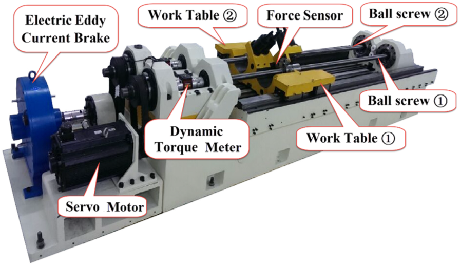
Test bench of ball screws.
Ball screw ① and ball screw ② are assembled with the servo motor and the electric eddy current brake, respectively. Work table ① and work table ②, which are connected by the pull-pressure sensor, are designed to connect with the two ball screws. The friction torque of ball screw ② (applied by the electric eddy current brake) must be offset before ball screw ① rotates. In this way, an axial load
Parameters used in the operation test.

Results and discussion
Table 2 shows the experimental and theoretical input torque of the feed drive system (ball screw ① and ball bearings mounted at both ends of the screw shaft) under different axial load and rotational speed. Under a certain rotational speed, the relative error of input torque calculated in this article decreases with increasing axial load. And under a certain axial load, the relative error decreases with increasing rotational speed. For a rotational speed of 1000 r/min, the relative error of input torque calculated in this article is within 15.9%, which indicates the model built in this article is valid.
Experimental and theoretical input torque of the feed drive system.

The experimental and theoretical results of the mechanical efficiency of the feed drive system under different axial loads and rotational speeds are shown in Figure 4. The experimental mechanical efficiency shows a similar tendency as that exhibited in the theoretical result, which proves the validity of the present model. Under a certain rotational speed, the mechanical efficiency increases with increasing axial load, which is consistent with the experimental results of previous findings.11,12 Under a certain axial load, the theoretical mechanical efficiency decreases with increasing rotational speed. This is because that the viscous friction torque,

Experimental and theoretical mechanical efficiency of the feed drive system.
It is worth mentioning that the maximum value of DN of ball screws is about

Theoretical mechanical efficiency of ball screw ①.
As we can see in Figures 4 and 5, the viscous torque and friction torque are the main factors leading to the decrease in the mechanical efficiency. Therefore, the comparison between the viscous torque and friction torque of ball screw ① is shown in Figure 6. The friction torque increases with increasing axial load, independent of the rotational speed. The viscous torque increases with increasing rotational speed and grease viscosity. The friction torque and viscous torque are very close when the grease viscosity is lower than 100 cst. However, when the grease viscosity is over 100 cst, the viscous torque will become higher than the friction torque, and the discrepancy increases with increasing rotational speed, which means the viscous torque will become the main factor leading to the decrease in the mechanical efficiency.

Viscous torque and friction torque of ball screw ①.
Conclusion
In this work, a new model for predicting the mechanical efficiency of ball screws and ball screw feed drive system is built based on the empirical equations for the friction torque of rolling element bearings. The main conclusions are as follows:
In an angular-contact ball bearing and a ball screw with one ball circle, both the basic static load rating and the angular velocity are the same; this means screw with N ball circles can be regarded as a combination of N angular-contact ball bearings.
For a rotational speed of 1000 r/min, the relative error of input torque of the ball screw feed drive system calculated in this article is within 15.9%, which indicates the model built in this article is valid.
The experimental results of the mechanical efficiency of the ball screw feed drive system show a similar tendency as that of the theoretical results. The discrepancy between the experimental and theoretical results is relatively small at a high rotational speed, which indicates the present model is more applicable for a relatively high-speed condition.
For ball screw ① used in this study, to maintain a mechanical efficiency higher than 90%, the rotational speed should be lower than 5000 r/min or the axial load should be higher than 1 KN.
When the grease viscosity is over 100 cst, the viscous torque will be higher than the friction torque, and the discrepancy increases with increasing rotational speed, which means the viscous torque will become the main reason leading to the decrease in the mechanical efficiency.
Footnotes
Appendix 1
Acknowledgements
The authors greatly thank the Key Laboratory of Performance Test and Reliability Technology for CNC Machine Tool Components of Chinese Machinery Industry for providing the experiment materials.
Handling Editor: Jan Torgersen
Declaration of conflicting interests
The author(s) declared no potential conflicts of interest with respect to the research, authorship, and/or publication of this article.
Funding
The author(s) disclosed receipt of the following financial support for the research, authorship, and/or publication of this article: This study has been supported by the National Science and Technology Major Projects of China (2016ZX04004007).