
Abstract
The spindle rotational accuracy is an important indicator to evaluate the characteristic of a machine tool. In this article, an easy-to-use measuring module is proposed based on virtual instrument platform. A new method for measuring rotational speed and angular orientation using an adaptive filtering method to processing the target installation eccentricity is proposed, instead of using the encoder. This method can reduce the measuring cost and make the measurement more convenient, without affecting the measuring accuracy. Meanwhile, the selective principle of target installation eccentricity for rotating sensitive direction is investigated by theoretical analysis and numerical simulation. Based on the proposed method, measuring module is developed. National Instruments data acquisition card and capacitive sensors are used to acquire the displacement signals of the spindle rotational error motion. Contrast experiments with the commercial measuring software are performed to validate the feasibility and repeatability of the proposed measuring module. The experimental results demonstrate that the developed measuring module can reach the same precision using less test parameters.
Keywords
Introduction
Rotational accuracy is one of the most important indicators which evaluate the dynamic performance of a machine tool spindle. The real axis line of rotation shifts from the ideal position due to a number of reasons including roundness error of the journal, defect and gap of the bearings, deformation of the spindle in response to load, and temperature or speed changes. 1 Spindle rotational error motions directly affect the profile and the surface roughness of the work pieces directly. 2 Thus, spindle rotational accuracy becomes one of the most important targets in the spindle evaluation. By measuring the rotational accuracy, the minimum profile error and the roughness error in the ideal cutting condition can be predicted. The measurement of rotational accuracy can also be used in the condition monitoring and fault diagnosis of machine tool.3–5
Rotational error motion can be classified into radial, axial, and tilt error motions in terms of the motion forms. However, in most cases, the three basic error motions exist simultaneously and are often illustrated using polar graphs, where the error motion is plotted against the angular position of the rotor. 6 Sensitive direction is the direction perpendicular to the work piece surface through the instantaneous point of machining or measurement. It can be classified into fixed and rotating sensitive directions. For sensitive direction, the work piece rotates with the spindle and the point of machining or measurement fixes, such as a lathe. Opposite case, like a jig borer, is called rotating sensitive direction. Total error motion is the complete error motion as recorded during experimental measurement.7,8
To even begin to investigate spindle rotational accuracy, the accuracy value must be measured accurately and precisely. Metrologists began to measure spindle error motion as early as 1900s. Scheslinger 9 was the earliest to establish specific tests for qualifying the performance of machine tool and key components such as spindle. Mechanical indicator was used to measure the total indicated reading (TIR), which is now recognized to be static method or the run-out of machine tool spindle. 10 Tlusty 11 and Bryan et al. 12 are considered as the founders of modern metrology of spindle rotational accuracy for developing complete methods for accurately quantifying spindle performance and presenting the results in the form of polar plots. Their methods are widely used in machine tool tests, and become the basis of the ANSI/ASME and ISO standards.7,8
In order to improve the measurement accuracy of high-precision spindle error motion, researchers developed nanometer-revolution capacitive sensors. Chapman 13 designed and built a spindle error analyzer (SEA) with a resolution of 5 nm to measure spindle error motion. Accuracy of spindle error measurement is mainly affected by the contribution of the errors including the form error and eccentricity of the target surface installed in the spindle, sensor offset, and thermal drift. 14 Ingenious measuring equipment and methods are also designed to promote measuring accuracy. In 1972, Donaldson 15 used reversal technique to separate form error of the test target and spindle radial error. Donaldson reversal method is considered as a complete separation technique. However, the separation accuracy is limited by reinstallation error of the test target or displacement sensor. Multi-probe methods can be used to separate spindle rotating error and form error according to simultaneous measurement of all the sensors.16–20 Multi-probe error separation is an online separation technique including at least two probes. Multi-step methods require many measurements to estimate the spindle error. The separation accuracy is affected by the number of measurement steps and sensor accuracy.21,22 Comparison researches of different separation methods are demonstrated by Cappa et al. 23 and Marsh et al. 24 A high-precision sphere or cylinder is used to inspect spindle rotating error to eliminate the influence of roundness error. 25 Zhang et al. 26 investigate the relationship of spindle accuracy and bearing preload using commercial measuring system.
From the literature reviews, it is worth noting that many techniques have been proposed to measure the rotational accuracy. In traditional measurements, the encoder is used to trigger the data acquisition (DAQ) system to provide angular signals. However, in some cases, the encoder is hindered to use because of cost and complexity of the equipment. Meanwhile, when processing the target eccentricity, the method of filtering first harmonic component is widely used. 27 The detailed influence of target installation eccentricity on the radial error motion measurement has never been thoroughly investigated, especially for rotating sensitive direction. Lion precision company has devoted great effort to developing SEA. Their commercial measuring system has been popularly used all over the word. However, so many parameters need to be set in the human–machine interface, which making the operation complicated.
In this article, a new method for detecting the fundamental frequency of the test spindle automatically using adaptive filtering is proposed. Using this method, rotational accuracy can be measured without using encoder, despite rotational speed of the spindle fluctuates. The developed measuring module in this research does not need to input too many operating parameters. Operator without specialized background can use the proposed measuring module easily. The influence caused by the target installation eccentricity on spindle radial error measurement is described, as well as simulation analysis. The selective principle of installation eccentricity value is investigated. Measuring module is developed based on the proposed method. National Instruments (NI) DAQ card, high-precision test dual ball, and nano-resolution capacitive displacement sensors are used to acquire displacement signals of a machine tool spindle. A series of experiments are performed to validate the feasibility and repeatability of the measuring module and the proposed measuring module can be applied to practical engineering.
Adaptive filtering algorithm
It is difficult to measure the spindle rotational accuracy directly. Artifacts such as precision test ball or test bar are used to aid the metrology to identify the dynamic features of the spindle. By measuring the artifacts mounted on the spindle shaft, the components of spindle rotational error motion can be measured. Figure 1 shows the discrete time samples of the measured displacement data in radial direction. The data express sinusoidal trends due to target installation eccentricity. A deviation is also found between the zero level and mean value of the data. Actually, the displacement probe has a zero level. But when fixing the probe, it is hard to adjust the mean value to the zero level. This problem can be solved by subtracting the mean value from the raw data first when processing measurement data.

Raw data of the displacement sensor before subtracting the mean value.
Compared with ideal sinusoidal signal of the eccentricity error, the error motion of spindle is non-stationary and time-varying. With respect to the eccentricity error, the error motion of the spindle is like strong noise. The characteristics of the error motion vary significantly due to the difference in rotational speeds. It is difficult to solve the problems of signal extraction using the conventional method in strong noise background. According to the input signals, adaptive digital filters can automatically adjust digital signal processing parameters, without manual intervention. 28 The structured flowchart of the proposed adaptive digital filter in this research is shown in Figure 2.
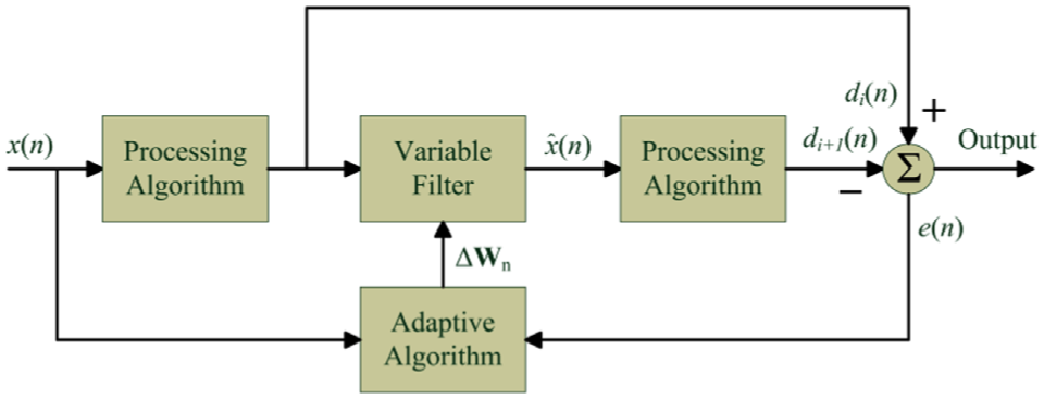
The structured flowchart of adaptive digital filter.
From the structured flowchart shown above, three basic components can be found. The variable filter is designed for the desired processing function. The adaptive algorithm is used for adjusting filter coefficients to improve the performance. The processing algorithm is applied to process the input signal to obtain parameter

If
Analysis of target installation eccentricity
The installation eccentricity of the target can be used for calculating rotational speed. However, if the value of eccentricity is large enough, measurement precision can be decreased significantly. In this section, the influence of the installation eccentricity is investigated using theoretical analysis and numerical simulation. In order to facilitate the analysis, roundness error of the test target can be omitted due to its high precision. The schematic diagram of radial error motion is shown in Figure 3.

Diagram of radial error motion in rotating sensitive direction of the spindle.
In the schematic diagram, spindle rotational error is expressed as δ, and φ is the phase difference between eccentricity and spindle rotational error motion, the installation eccentricity of the target is expressed as e.
The displacement sensor values


where θ is the corresponding angular position of sampling, and R is the radius of the test ball.
The position changes of the target in the X- and Y-axes can be projected to the sensitive direction by

where r0 is the value of the basic circle radius set by alignment of the displacement probes and the test ball. By adjusting the value of r0, the plot of the error motion would be easy to identify, without affecting error motion value. In accordance with ANSI/ASME standard or ISO standard, error motion values can be evaluated.
In order to investigate the influence of installation eccentricity e, spindle rotational error δ can be set to zero. Substituting equations (2) and (3) into equations (4) and (5), the following equation is deduced

Equation (6) is obtained by expanding

The theoretical derivation verifies eccentricity error e not only influences first harmonic component, but also other odd order modes harmonic components. With the elevation of order, the components with e gradually become smaller. The conventional method by filtering first harmonic component cannot eliminate the eccentricity error completely.
In the numerical simulation, R is set to 20 mm, A and B are set to 30 mm. By changing the value of eccentricity from 0 to 100 μm, the corresponding evaluated synchronous error motion values caused by installation eccentricity can be obtained according to ANSI/ASME standard and ISO standard. These error motion values cannot represent the real spindle error and are only obtained by the target installation eccentricity mathematically. The evaluated synchronous error motion values vary from 0 to 0.53 μm, as shown in Figure 4. When the value of installation eccentricity is small, the effect is considered as negligible. However, for the measurement of high-precision machine tool spindle, the effect of installation eccentricity should not be neglected.
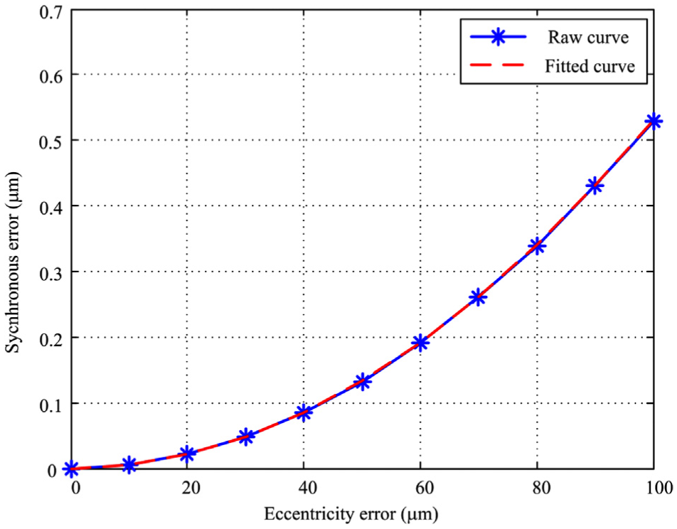
Synchronous error motion value caused by installation eccentricity in different eccentricity.
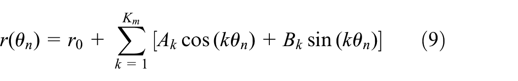
Using polynomial fitting, the relationship between the installation eccentricity error and the synchronous error motion value

In the measurement, the fitted equation can be used to evaluate the influence of installation eccentricity error on radial synchronous error motion value. When the magnitude of synchronous radial error motion value is estimated approximately, the maximum installation eccentricity error can be calculated by equation (8)

where
The projection error motion can be expressed using the harmonic function as follows
where
Supposing the signals of the spindle radial error motion

where
Pearson Correlation Coefficient (PCC) of raw signals and filtered signals

in which
The value of PCC varies between −1 and 1. The closer the value is to 1, the more similar the filtered signals and raw signals are. The minimum installation eccentricities of different signals can be obtained, which ensuring correlation coefficients are no less than 0.98. The relationship between standard deviations of the spindle radial error and the corresponding minimum installation eccentricities is shown in Figure 5.

The relationship between standard deviation of the spindle radial error and the corresponding minimum installation eccentricity.
The fitted curve is also shown in Figure 5, demonstrating good linear relationship. The relationship between standard deviation of spindle error and the minimum installation eccentricity error can be obtained, as given by equation (12)

where
From the theoretical analysis and numerical simulation, target installation eccentricity can decrease measuring accuracy in spindle rotational error motion measurement. In the preliminary phase, the maximum and minimum installation eccentricity error can be evaluated by the displacement data. When the influence caused by installation eccentricity is not ignorable, targets should be adjusted to the range between
Development of measuring module
In accordance with the proposed method in section “Adaptive filtering algorithm,” measuring module is developed based on virtual instrument platform. In the developed module, rotational speed of the test spindle can be measured automatically due to the installation eccentricity signals, without using encoder or other measuring equipment. When rotational speed changes, there is no need to modify any parameter to satisfy the measurement requirement. The structured flowchart of the measuring module is shown in Figure 6.
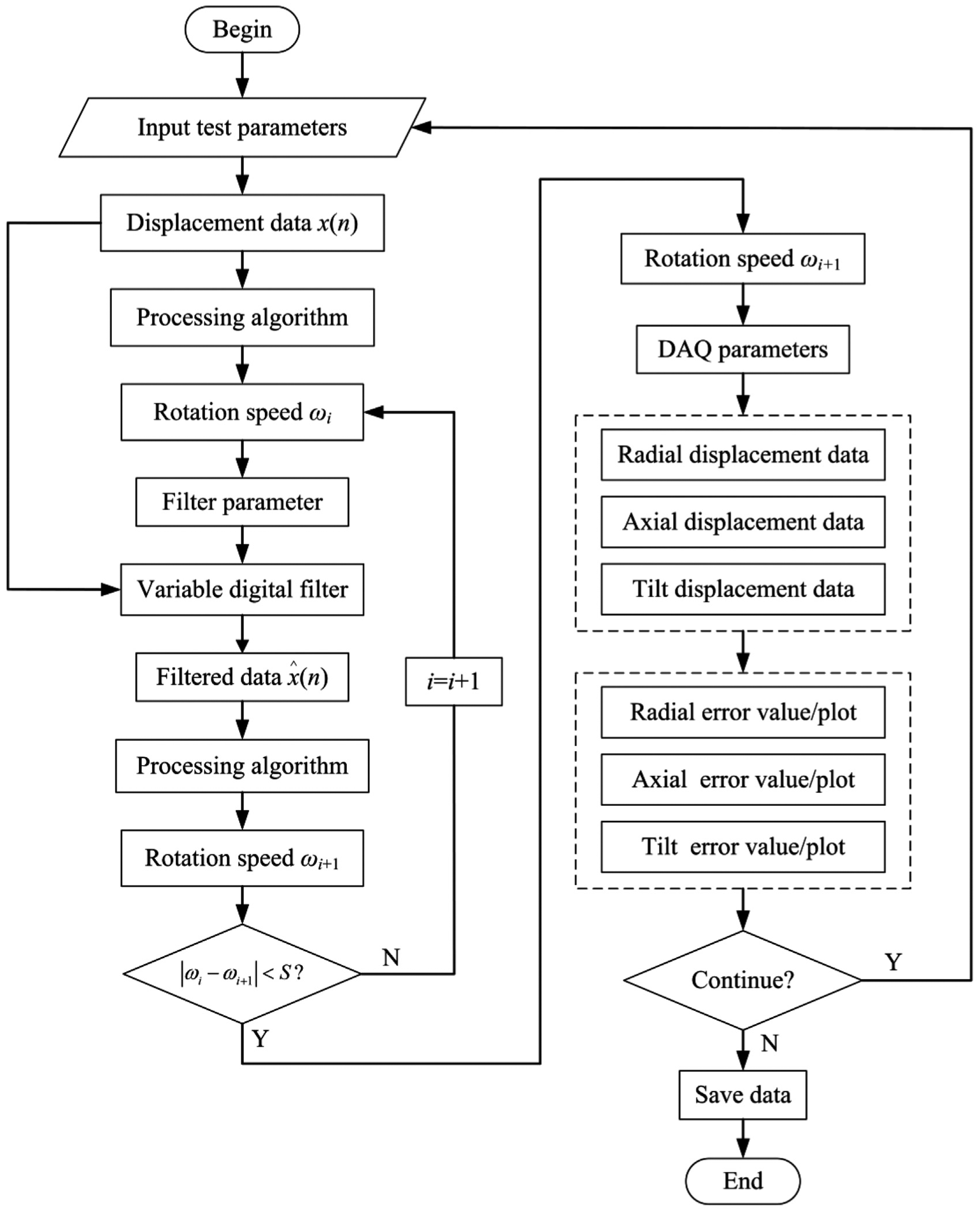
The structured flowchart of the measuring module.
In the processing algorithm, the input signals are carried out threshold processing first. The mean value of the input signals can be chosen as the threshold value in the processing. Square-wave signals can be obtained. From the square-wave signals, sampling points of per cycle can be calculated from one rising-edge to the next rising-edge. Accurate information of rotational speed can improve the measuring accuracy. In accordance with ANSI/ASME standard or ISO standard, least square circle (LSC) evaluation method is used to assess the synchronous radial error motion of the spindle. Actually, the calculation of synchronous error motion value is a process of nonlinear least square fitting. The calculation process is expressed by equation (13)

where
From the LSC center, a circumscribed circle and an inscribed circle can be obtained. Synchronous error motion value

in which
Asynchronous error motion value

in which r(θ)min and r(θ)max denote the maximum and the minimum values of the total error motion from the same angular position θ, respectively.
The displacement signals are acquired by measuring module which developed by LabVIEW software and can be displayed for online analysis. The whole measuring module has a friendly human–machine interface which is easy to use, as shown in Figure 7. There is no need for user to input too many test parameters.

Human–machine interface of the module.
The information of different spindle error motion can be displayed in corresponding tab pages, including numerical and graphic display. User also can modify test or display parameters manually. The main tab pages are shown in Figure 8.

Tab pages of different spindle error motion.
In the experimental setup, NI DAQ card USB-6251, capacitive displacement sensors, and the corresponding driver (CPL-290) are applied to acquire the displacement data. Table 1 shows the technical parameters of the capacitive sensors used in the experiment. Each capacitive displacement sensor is factory-calibrated to provide a linear output for the given target displacement. 29 The measurements are carried out in a temperature-controlled environment of 20°C ± 1°C. So, we neglect the thermal drift caused by the environment and the spindle itself.
Technical parameters of capacitive sensor.

A high-precision test dual ball (roundness errors are both less than 30 nm) mounted in the rotor of the spindle is rotated with the spindle. The SEA of Lion Precision is adopted as a reference for comparison purpose. Electro-optical sensor is also used to generate a pulse signal when spindle rotates a revolution for SEA. Figure 9 gives the physical picture of the whole experimental setup.
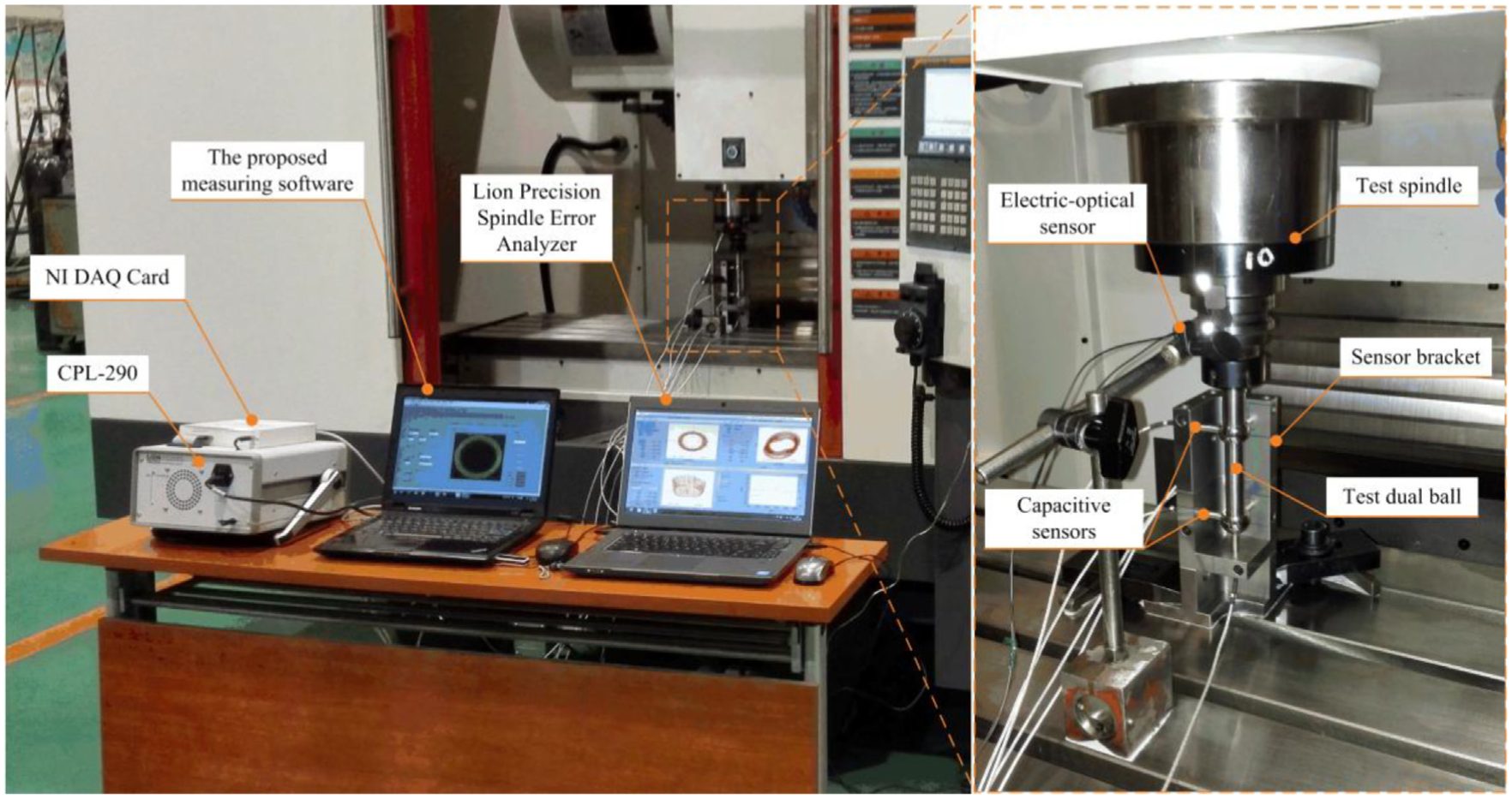
Physical picture of the whole experimental setup in laboratory.
Measurement data are acquired at the different spindle speeds from 100 to 6000 r/min. Tables 2–4 give the contrast data for different kinds of radial error motion values evaluated by the proposed measuring module and Lion precision SEA.
Comparisons of synchronous radial error motion value at different spindle speeds (μm).

Comparisons of asynchronous radial error motion value at different spindle speeds (μm).

Comparisons of total radial error motion value at different spindle speeds (μm).
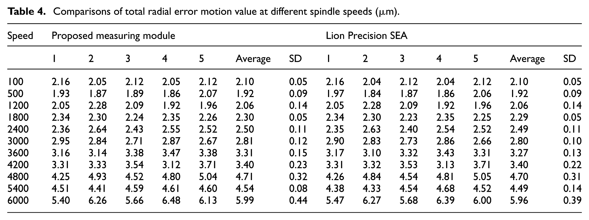
The trend charts are shown in Figure 10. “SEA” represents the error motion values evaluated by Lion Precision SEA, while “PMM” represents the error motion values evaluated by the proposed measuring module in this research. The contrast results demonstrate that evaluated error motion values by the proposed measuring module are quite consistent with SEA values. The maximum difference is 0.11 μm (about 6%) at 6000 r/min for asynchronous error motion. The difference can be caused by a number of factors, including types and parameters of the filters, evaluation methods, or other random factors.

Evaluated radial error motion values at different spindle speeds.
Conclusion
This article presents a new measuring module for measuring rotational accuracy of machine tool spindle. In the module, a new method for measuring rotational speed using the installation eccentricity of target is developed. An adaptive filtering method is used to extract the fundamental frequency accurately without human intervention, which makes the field measurement more convenient and efficient, despite the rotational speed exists fluctuation. The influence caused by target installation eccentricity is also investigated theoretically and numerically. The selective principle of installation eccentricity value is presented. NI DAQ card and nano-resolution capacitive displacement sensors are used to acquire displacement data. In accordance with the proposed method and international test standard, different spindle rotational error motion values can be evaluated in the proposed module. The numerical and graphic results can be displayed in the human–machine interface. Spindle rotational error motion can be measured in real operating conditions, and the working accuracy of the machine tool can also be predicted. A series of contrast experiments are carried out at various spindle speeds using the proposed module and the commercial measuring software. The maximal difference is 0.11 μm (about 6%). The experimental results demonstrate that the proposed measuring module is feasible and has good repeatability.
Footnotes
Handling Editor: Kang Cheung Chan
Declaration of conflicting interests
The author(s) declared no potential conflicts of interest with respect to the research, authorship, and/or publication of this article.
Funding
The author(s) disclosed receipt of the following financial support for the research, authorship, and/or publication of this article: This work was supported by National Science and Technology Major Project of China under Grant No. 2014ZX04011011.