
Abstract
As the core component of machine tool, the thermal characteristics of the spindle have a significant influence on machine tool running status. Lack of an accurate model of the spindle system, particularly the model of load–deformation coefficient between the bearing rolling elements and rings, severely limits the thermal error analytic precision of the spindle. In this article, bearing internal loads, especially the function relationships between the principal curvature difference F(ρ) and auxiliary parameter nδ, semi-major axis a, and semi-minor axis b, have been determined; furthermore, high-precision heat generation combining the heat sinks in the spindle system is calculated; finally, an accurate thermal model of the spindle was established. Moreover, a conventional spindle with embedded fiber Bragg grating temperature sensors has been developed. By comparing the experiment results with simulation, it indicates that the model has good accuracy, which verifies the reliability of the modeling process.
Introduction
A study on the thermal model and improvement of the computer numeric control (CNC) machine tool spindle accuracy is the most important pursuit for researchers in precision manufacturing field. Moreover, obtaining an accurate model of the spindle is beneficial to analyzing the bearing running status and the thermal error. However, the fundamental prerequisite is to analyze the spindle bearing internal action mechanism.
There will be a large amount of heat when the spindle is running at a high speed. And the heat generated by the bearing is the main heat source of the spindle. To calculate the heat source of the bearing, the bearing internal loads’ analysis has to be done. According to Harris’ 1 research, the internal loads of bearing have complex relations with the contact angles between the balls and raceways, as it exits many nonlinear equations with coupled parameters; many researchers, such as C Jin et al., 2 T Xu et al., 3 and C Ma et al., 4 have done the bearing internal loads’ analysis in the recent years. But they did not show the detailed calculation steps, especially the calculation of load–deformation coefficient, which is coupled with the contact angles between the ball and raceway and is different at each ball position causing ball centrifugal force and gyroscopic moment; and semi-major axis a and semi-minor axis b of the spinning contact area between the balls and raceways are not given clearly either.
Only when the bearing internal action mechanism is analyzed, the bearing heat generation can be received using the data of bearing internal loads, and the spindle temperature field can be solved. Based on the bearing load analysis, the variation in the spindle temperature field machine tools can be analyzed based on finite element model (FEM), such as C Ma et al., 4 JK Choi and DG Lee, 5 M Mori et al., 6 H Zhao et al., 7 E Creighton et al., 8 D Chen et al., 9 WS Wang et al., 10 Q Yang et al. 11 and S Jiang and H Mao. 12 Based on FEM method, the accurate result can be obtained, but the result is based on the accurate calculation of heat source, not the method itself, and the heat sources and boundary conditions of the spindle system have been precisely calculated in this article.
In this article, a conventional spindle was studied; the calculations of bearing internal loads, heat generation, and heat sinks of the spindle are described in detail. Moreover, the specific relationships between the principal curvature difference F(ρ) and auxiliary parameter nδ, contact ellipse semi-major axis a, and semi-minor axis b to accurately calculate the ball spinning friction torque on the contact areas were given out precisely, and also FEM method is used to solve the thermal model. In addition, the fiber Bragg grating (FBG) temperature sensors were selected to accomplish the measurement, which was the new sensing material in monitoring the mechanical system dynamic.13,14 The nomenclatures in this article are shown in Table 1.
Nomenclature.

Bearing internal loads’ analysis
The angular contact ball bearings are the most popular bearing type used in the high-speed spindle for machine tools, which are also utilized in this article. For a thermal model of spindle system, the accurate heat sources have to be received. For the generated heat of the angular contact ball bearing, the internal loads of the bearings have to be obtained first, which are related to the bearing generated heat. Modeling the bearing internal loads is based on the quasi-static mechanical analysis of the bearing, which contains the ball centrifugal force and bearing gyroscopic moment, which is the classical and most popular method, and also applied in this article. For angular contact ball bearing, simplified schematic diagram is shown in Figure 1.

Simplified schematic diagram of angular contact ball bearing.
When loads and rotation speed were applied to the bearing, the ball positions will be changed. First, the force balance equations can be established. The force applied to every rolling element is depicted in Figure 2.

Ball loads at angle ψj.
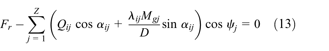
According to Figure 2, the ball force balance equations can be obtained
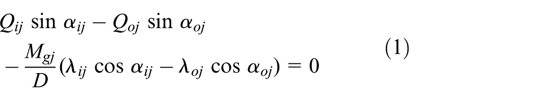

where


nδ curve fitting methods’ contrast.
For a specific bearing, when the contact angles are known, the principal curvature difference F(ρ) is decided. So using equation F1(x), nδ can be obtained, which can be used to calculate the bearing load–deformation coefficient. Particularly, when the principal curvature difference F(ρ) of the contact area is in the range of 0.85–0.999, which are the appropriate values for angular contact ball bearing. This calculation method can avoid the complicated process to build the relationship with the contact angles and show their relationships clearly.
For steel ball bearings in this article, the centrifugal force and gyroscopic moment acting on a ball are calculated as follows2–4


If outer raceway control is approximately applied at a given ball location

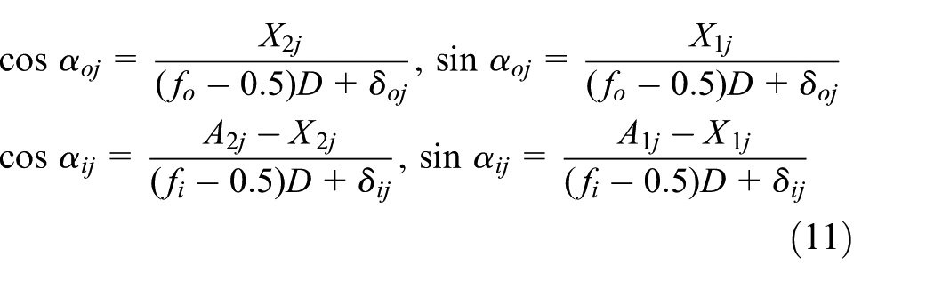
Second, the relative positions of the ball and inner and outer raceway groove curvature centers can be found, as shown in Figure 4. It is assumed that the outer raceway groove curvature center is fixed in space and the inner raceway groove curvature center moves relative to the fixed center. As observed from Figure 4, the contact angles of the ball and inner and outer raceway are dissimilar. The relative axial and radial deformations between the inner ring and the outer ring are δa and δr, respectively. A1j, A2j and X1j, X2j are the auxiliary parameters. δij and δoj are the deformations of the inner and outer raceway at angle ψj, respectively.
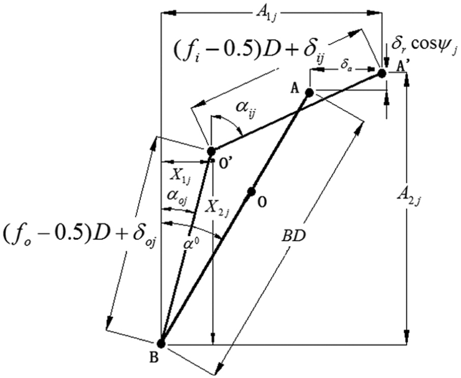
Relative positions of ball center and raceway groove curvature centers.
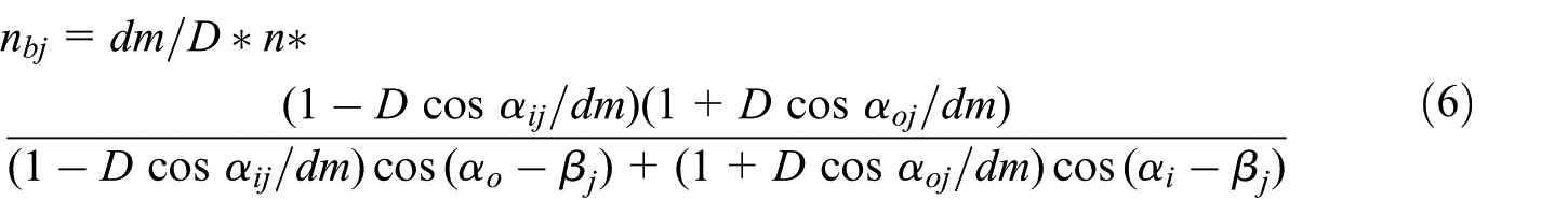
The auxiliary parameters A1j, A2j, X1j and X2j and the equilibrium equations of the entire bearing are defined as follows


where Fa and Fr are the applied loads on the bearing.
For calculating bearing internal loads, αi, αo, δi, δo, X1, X2, A1, A2 at each ball position, inner ring, and outer ring relative deformations δa and δr should be determined, combining with nonlinear equations (1), (2), and (9)–(13), which can also be solved by Newton–Raphson method. After obtaining all the parameters, the bearing working status can be received.
The specific parameters of 7012AC bearing are shown in Table 2. The bearing without radial load is calculated in Figures 5–7.
The specific parameters’ values of the bearing.


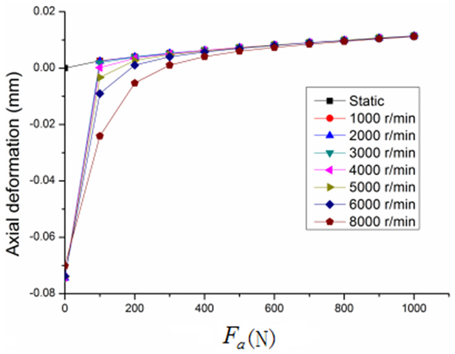
Axial deformation versus different axial loads and spindle speed.
From Figure 5, it can be observed that the contact angles αi between the balls and the inner raceway are comparatively bigger than the contact angle αo between the balls and the outer raceway in the same bearing axial load and speed conditions; the smaller the axial load, the bigger the difference between the contact angles at the same bearing rotation speed. And in a ball bearing, depending on the contact angles, ball gyroscopic moments and ball centrifugal forces can be of significant magnitude such that the inner raceway contact angles tend to increase and the outer raceway contact angles tend to decrease. From Figure 6, the contact load Qi between the balls and the inner raceway is relatively smaller than the contact load Qo with the same bearing axial load and speed; the contact loads Qi and Qo are symmetrically distributed on the sides of static situation with different axial loads. And the axial deformations tend to become similar to the static station with large axial loads at big bearing speed, which can be observed in Figure 7.
Spindle thermal analysis
Bearing heat generation
In the machine tool operations, the major heat sources include the heat generated by the cutting process and the heat from the bearings. It is assumed that the majority of cutting heat is taken away by coolant, and therefore, the heat generated by bearings is the dominant heat causing the thermal deformations. After receiving bearing working data, the heat generated by a bearing can be computed by the following equation 2

where n is the rotating speed of the bearing, M is the total frictional torque of the bearing, and Hf is the generated heat. The frictional torque M is a sum of three torques: (1) the torque due to applied load, M1; (2) the torque due to viscous friction, M0; and (3) the torque due to spinning motion at contact area, Msi(o).
The torque due to the applied load
The torque due to the applied load can be empirically approximated by the following equation2–4

where f1 is a factor depending on the bearing design and relative load, and for single-row angular contact ball bearing, f1 = 0.0013(p0/c0)0.33; P1 is the dynamical equivalent load, and for angular contact ball bearings, P1 = Fa − 0.1Fr;
The torque due to viscous friction
The torque due to viscous friction is related to bearing type, rotating speed, and lubricant type. For bearings that operate at moderate speeds and under non-excessive load, the viscous friction torque can be empirically expressed as follows2–4

where f0 is connected to bearing type and lubrication mode, and for single-row angular contact and grease lubrication ball bearings, f0 = 2; v is the movement viscosity of the lubricant under operating temperature, and the movement viscosity of grease lubrication is 30.5 cst at 20°C, 18 cst at 40°C, 10 cst at 60°C, and 1 cst = 10−6 m2/s.
Spinning torque at contact area
The spin friction torque Msi(o) generated by ball’s spinning motion can be expressed as2,4
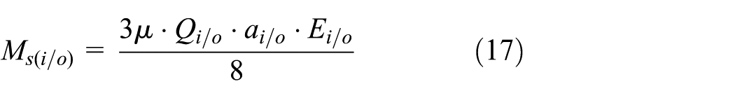
So the total friction torque due to ball’s spinning motion can be obtained as

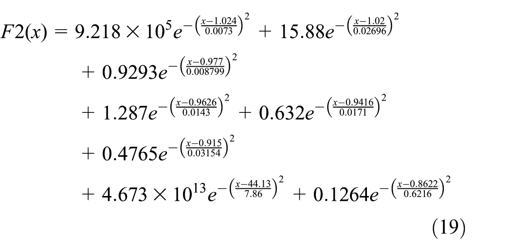
For calculating Ms, the elliptical semi-major axis and eccentricity ratio should be computed. Also, the relationships between the contact ellipse semi-major axis a, semi-minor axis b, and principal curvature difference F(ρ) were obtained by curve fitting; the specific results are shown as F2(x), F3(x) (Figure 8); the original data were also cited in Okamoto 15


The specific curve fitting methods’ contrast results.
Through equations (19) and (20), the contact ellipse semi-major axis and semi-minor axis can be decided by the principal curvature difference F(ρ); taking full advantage of this method can save large amount of computing time. According to the bearing 7012AC, the results of three different friction torque and heat generation are shown in Figures 9–11.

Spinning friction torque of each ball.

Heat generation caused by viscous friction.

Heat generation caused by applied load friction.
Heat sinks in spindle
The spindle heat sinks mainly include the convection between the shaft and air; the ambient air; the thermal resistance between bearing outer ring and housing, bearing inner ring, and shaft; and the thermal conduction between the components.
First, the convection η between the shaft and air can be defined as 12

where Nu = 0.133Re2/3Pr1/3, d is the shaft diameter, Re = V × d/vair, Pr is the Prandtl number of air, V is the speed of air on the shaft surface, vair is the viscosity coefficient of air, and kair is the air conduction coefficient. The specific result is shown in Figure 12.
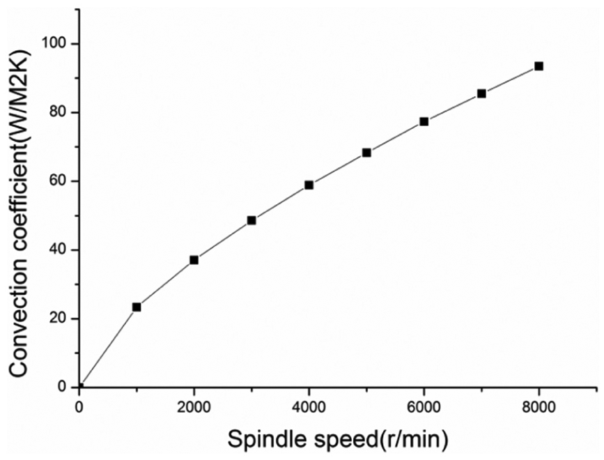
The convection between shaft and air under different spindle speed.
Second, a free convection coefficient can be assumed for ambient air around stationary surfaces such as the spindle housing. The coefficient can be obtained as a = 9.7 W/(m2 K) according to Jiang and Mao. 12
Third, the thermal resistance between the bearing outer ring and housing is the reciprocal number of the thermal conduction coefficient number Π between the clearances.
12
And the thermal conduction coefficient number

where hgap is the average of the clearance, hring is the thickness of the ring, λring is the thermal conduction coefficient of the bearing ring, λair is the thermal conduction coefficient of air, and A is the contact area. According to the specific values, the thermal in this article is 1439.5 W/m2 K of the shaft and bearing outer ring and 908.75 W/m2 K of the housing and the bearing inner ring. All the needed boundary conditions for bearing temperature analysis are conformed so far.
Spindle temperature field simulation and measurement
Spindle temperature field simulation
The general and popular way for spindle thermal analysis is using the commercial FEM software, such as ANSYS. ANSYS 14.0 was selected for solving the spindle thermal field and bearing temperature rise in this article. The spindle system is simplified and reconstructed by computer-aided design (CAD) software. Specially, the mesh size is refined at the bearings to guarantee the results’ accuracy. After loading all the boundary conditions, the spindle field is obtained at a spindle speed of 1000 r/min and axial load of 0 N; the specific results are shown in Figure 13.
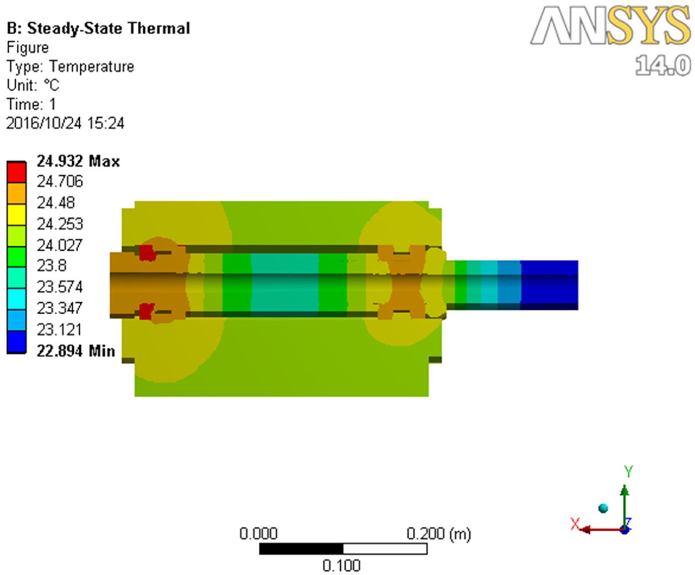
Spindle temperature field simulation results under 2000 r/min and axial 0 N.
The simulation results show that the highest temperature area is at the position of bearings, especially at the spindle front end. And because of the mounting position of the experiment setup, there is no convection on the bottom face of the spindle housing; the bearing temperature has uneven temperature field, but the difference can be ignored.
The experimental apparatus is shown in Figure 14. The experimental apparatus is mainly a spindle system. The coupling connects the servo driver and the shaft to avoid the motor’s generated heat flow into the spindle housing; the milling force is uploaded to apply the axial loads; the housing is fixed on a vibration isolation platform. Figure 15 shows the specific experiment setup.

Experimental apparatus.

The specific experiment setup.
The bearing outer ring temperature measurement is based on FBG temperature sensor, which has unique advantages in small installation space and harsh environment.13,14 The specific layout positions of FBG are shown in Figure 16. There is a ring groove at the contact position of the housing and the bearing outer ring; FBG temperature sensors are arranged in the substrates, which are printed by three-dimensional (3D) printer. Thermal conductive grease fills the gap between FBG and the bearing outer ring.

FBG sensors’ installation locations.
After the installation of FBG sensors, they should be calibrated, since the sensitivity of FBG will be affected by thermal expansion of the thermal grease and its own bending. The whole bearing slider was placed in a constant temperature environment to calibrate the FBG sensors. The specific results are shown in Figure 17. From Figure 17, every FBG temperature sensor has a very good linear character to the temperature signal. The average slopes of the fitting curves are 10.72, 10.75, 10.27, 10.9, 10.44, and 10.96 separately.

The calibration results of FBG sensor.
Spindle bearing temperature measurement
Bearing temperature rise is the most concerned parameter in the machine tool spindle system, which is related to the running state of bearing, spindle working life, and spindle thermal error; the measurement of bearing temperature is helpful to ascertain the bearing running characteristic and analyze the spindle thermal error. So monitoring the bearing temperature plays a critical role in the work process of spindle. So the bearing temperature was selected to verify the model built in this article. Figure 18 shows the measurement results of FBG temperature sensors at spindle speed 2000 r/min and axial load 0 N. From Figure 18, it can be observed that the thermal balance is achieved at 150 min; when the spindle stopped running at 230 min, the bearing temperature has small increase, caused by the decrease in shaft and air convection.
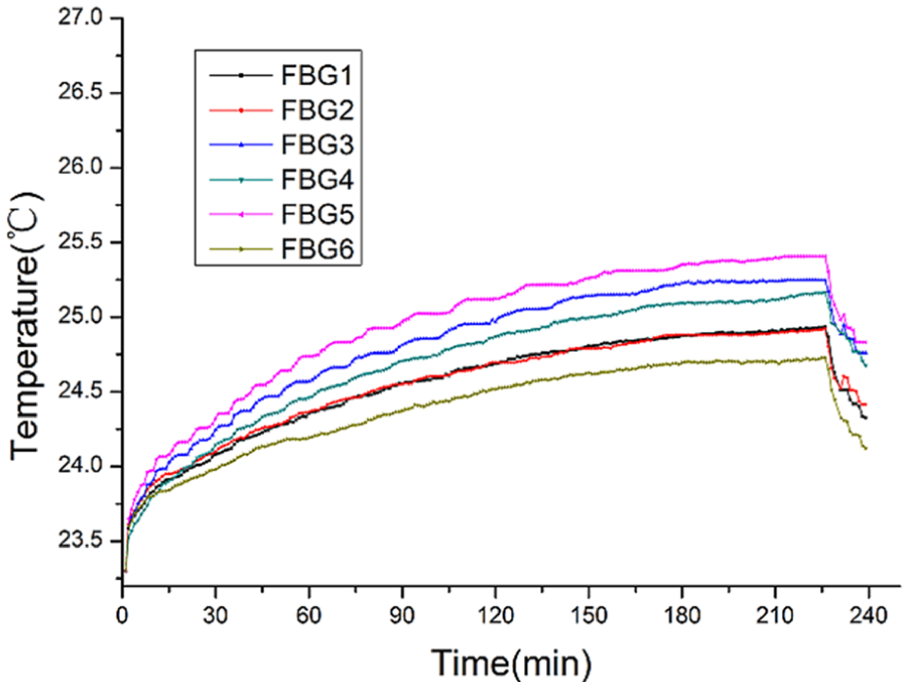
The specific measurement temperature of FBG sensors.
After thorough analysis of the spindle heat generation and heat sinks in the spindle system, the measurement and simulation results of the bearing temperature under 1000 r/min, 2000 r/min, 3000 r/min, 0 N, 1000 N axial loads, and different ambient temperatures have no much difference with error smaller than 1°C. The specific contrast results are shown in Figure 19.

The contrast results between the simulation and measurement results.
Conclusion
Nowadays, the spindles can be divided into two groups: conventional spindle and motorized spindle; the latter is developed from the former, but the core units—bearings—have not been changed. So a study on the traditional spindle can push for a resolution for the problems on the machine tool spindle. In this article, the thermal model of a conventional spindle is developed; the bearing internal loads between the balls and raceways, the heat generation, and heat sinks of a conventional machine tool have been put in detail further. Especially, the load–deformation coefficient between the raceways and the balls is explained clearly. Also, the functions between the principal curvature difference F(ρ) and the auxiliary parameter nδ, semi-major axis a, and semi-minor axis b have been clearly given out. These functions can directly be utilized in the future to calculate the bearing internal load distribution and the spinning torque at the contact areas, reducing the whole calculating time. After receiving the bearing simulated temperature, the embedded FBG temperature sensors have been used to measure and verify the simulation bearing temperature. The contrast results show that the thermal model caught up in this article can be used for spindle state analysis.
Footnotes
Academic Editor: Jiin-Yuh Jang
Declaration of conflicting interests
The author(s) declared no potential conflicts of interest with respect to the research, authorship, and/or publication of this article.
Funding
The author(s) disclosed receipt of the following financial support for the research, authorship, and/or publication of this article: This experimental study was supported by National Natural Science Foundation of China: Study on heavy-duty NC machine tool monitoring and real-time thermal error compensation method (no. 51475343) and International Science & Technology Cooperation Program of China (grant no. 2015DFA70340).