
Abstract
The bearing preload plays an important role on the bearing performance, particularly the important characteristics of the bearing include bearing temperature increases, the bearing fatigue life, and ball skidding. Generally, the bearing preload contains the initial bearing preload and the thermal-induced bearing preload. Moreover, the bearing performance is closely related to machine tool accuracy. Obtaining an optimal bearing preload can improve the spindle work accuracy of machine tools. A method for determining optimal bearing preload over a wide range of speeds is given in this article. The method is based on the aforementioned factors that affect bearing performance, synthetically considering the initial preload and thermal-induced bearing preload, and it is verified both experimentally and with simulations. The results show that there is a minimum bearing preload value for avoiding the bearing ball skidding; the bearing temperature rise more than 30°C can be hardly achieved in the normal speed range, the fatigue life decides the biggest bearing preload; and the method is applicable to machine tool spindle usage.
Introduction
The spindle is a core component of machine tools, and its dynamic characteristics have a significant influence on workpiece surface quality and machine tool accuracy. With the development of high-speed machining, particularly high-speed milling, heavy cutting at low speed and light cutting at high speed are often performed with a single machine tool spindle. Thus, high stiffness at low speed as well as low temperature rise at high speed are required characteristics. To provide a suitable rotation rate for different machining processes, a single machine tool spindle should work over a wide range of speeds. A conventional spindle mainly consists of bearings, a motor, and a shaft. From the design of the spindle, it is obvious that the running states of its bearing, more than other components, are tied closely to the dynamic characteristics of the spindle, particularly the bearing stiffness, temperature rise, fatigue characteristics, and the bearing ball skidding.
In contemporary machine tool spindles, the angular contact ball bearing, which can sustain axial and radial loading simultaneously, is widely used. Preload of the angular contact ball bearings is generally applied to obtain high stiffness, restrain vibration, and enhance rotational accuracy of the machine tool spindle,1,2 which experiences mostly axial preload. Proper preload of the angular contact ball bearing plays a large role in the running characteristics of the bearing and spindle.2–4 Consequently, methods for determining optimum bearing preload are of great significance. Many researchers are currently studying bearing preload optimization. S Jiang and H Mao 5 calculated the bearing life with different amounts of preload at different spindle speeds and developed a method for the optimization of preload at low spindle speed based on bearing fatigue life. SA Spiewak and T Nickel 6 proposed a complete method for obtaining spindle stiffness measurements with an exciter and acceleration sensors and estimated the spindle preload based on these measurements. T Xu et al. 7 analyzed optimum preload under ball-skidding conditions and achieved a limited bearing temperature rise when the spindle speed was lower than 10,000 r/min. Y-K Hwang and C-M Lee. 8 provided curves relating bearing preload and bearing fatigue life and proposed bearing preload optimization methods based on spindle stiffness and bearing fatigue life. In these studies, the researchers measured bearing temperature directly. Based on these data, they adjusted bearing preload accordingly. Furthermore, these researchers used spindle rigidity, ball skidding, and even transient preload for determining the optimal bearing preload. From these studies, it is apparent that no definitive standards exist for bearing preload optimization methods.
In this article, a comprehensive method for obtaining an optimum preload value is provided. This method is based on the analysis of the influences on bearing stiffness, bearing temperature rise, bearing fatigue life, and bearing ball skidding to obtain a reasonable bearing-applied preload.
Abbreviations and definitions are shown in Table 1.
Definitions.

Experimental setup
Figures 1 and 2 show the specific components of the spindle system which is designed for this research, including the driver, coupling, shaft, housing, and cutting force simulation device. As a result of the bearing arrangement “O,” the axial force in the shaft is equal to the double axial preload on the bearings. The temperature rise at the bearing outer ring is measured by fiber Bragg grating (FBG) temperature sensors. The average temperature rise of the FBG temperature sensor measurement data is used in this article.

The bearing arrangement and FBG temperature sensors locations.

The spindle system used in the experiment.
Also a preload upload device is designed in this article. The bearing preload covers the initial preload and thermal-induced preload comprehensively, so to optimize bearing preload, it has to design a preload upload structure which can avoid the thermal-induced preload influence or take in the thermal-induced preload. In this article, the bearing preload applied structure is shown in Figure 3. The pipe and chamber are filled with oil; the pressure sensor measures the oil pressure in the pipe, which is connected with the spindle housing chamber between the housing and bearing block, increasing the oil pressure can move the bearing block to upload the force on the bearing outer ring; the fine tooth thread on the upload device changes the space in the pipe and oil hole to increase and decrease the pressure. When the thermal-induced preload acts on the bearing outer rings, which means the structure has thermal expansion, the total bearing preload can be decreased by increasing the space in the pipe.
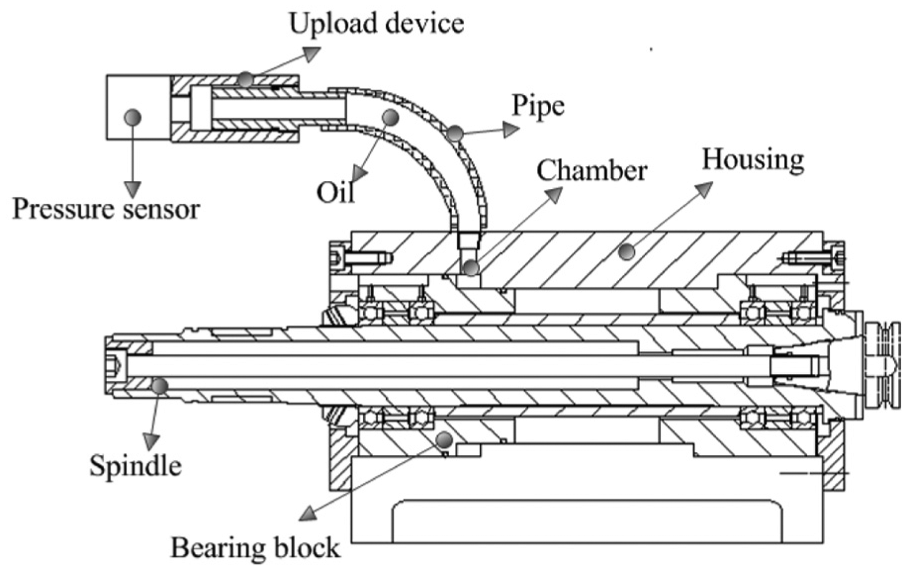
The preload upload structure used in this article.
Influencing multiple parameters on the bearing performance of preload
Distribution of internal loading in a ball bearing
A simplified schematic of an angular contact ball bearing is shown in Figure 4. Figure 4 illustrates the free contact angle, which is the angle between any two lines perpendicular to the rotation axis of the bearing passing through the ball and raceway contact points. The free contact angle


Simplified schematic of an angular contact ball bearing.
Under zero bearing preload,

Relative positions of the ball center and raceway groove centers of curvature.
Per Figure 5, the new contact angle can be defined as follows
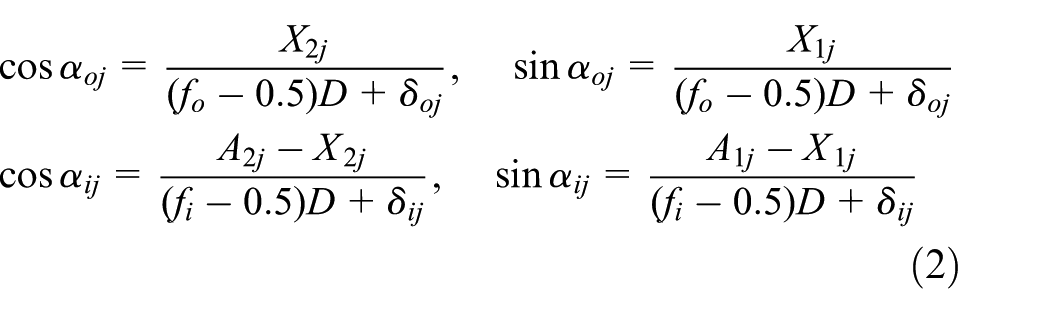
where
Mechanical analysis of the bearing is conducted to establish the balance equation of the bearing. The force applied to each ball in the bearing is illustrated in Figure 6.

The force applied to each ball.
Based on Figure 6, the ball balance equations can be obtained


where
The equilibrium equations of the entire bearing can be established as follows


To calculate the internal loads of the bearing, the values of
Bearing ball skidding
Bearing ball skidding induces spindle improper vibration and severe bearing temperature rise, and it has to be avoided. The ball centrifugal force and the contact area decrease as the speed increases.7,9 Thus, the ball skidding effect of the bearing increases as a result of the reduced contact area. Furthermore, the ball and raceways lose contact at a certain bearing rotation speed. When ball skidding occurs, friction increases, leading to a large amount of heat generation. At a certain axial bearing preload, there exists a critical speed at which the contact area is zero. Hirano 10 has determined the criterion for bearing skidding as follows

where
Spindle system simulation and bearing preload influencing analysis
Results of calculations
A 7012AC bearing was used in this experiment setup. Its parameters are given in Table 2.
Bearing parameter values.

The nonlinear equations were solved by software MATLAB. The results of these calculations are shown in Figures 7 and 8.

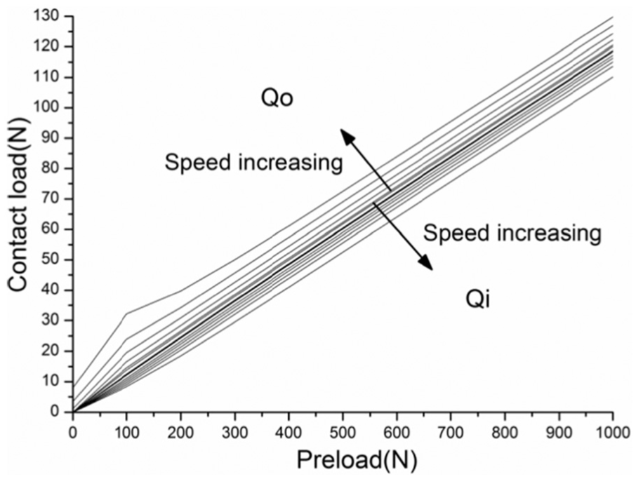
As can be observed in Figures 7 and 8, the contact angles between the ball and the raceways increase with the bearing preload. The contact angle between the ball and the inner raceway decreases with the bearing speed, and the contact angle between the ball and the outer raceway increases with the bearing speed. The contact angles of the inner and outer rings tend to become consistent, approaching the contact angle in static situations. The contact loads of the raceways appear fairly linear, and the axial deformation appears to increase slowly with bearing rotation speed.
Spindle bearing temperature rise simulation
Bearing heat generation
In a traditional spindle, the bearing is the main heat source. It is assumed that the majority of cutting heat is taken away by coolant and therefore the heat generated by bearings is the dominant heat causing the thermal deformations. After computing the bearing working condition data, the heat generated by a bearing can be computed with the following equation 9

where n is the rotating speed of the bearing, M is the total frictional torque of the bearing, and
The torque due to the applied load can be empirically approximated by the following equation

where
The torque due to viscous friction is related to the bearing type, the rotational speed, and the type of lubricant. For bearings that operate at moderate speeds under non-excessive load, the viscous friction torque can be empirically expressed as follows
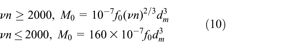
where
The spin frictional torque

Thus, the total frictional torque due to the spinning motion of the ball can be obtained as

Heat sinks in the spindle
The spindle heat sinks produce convection between the shaft and air, the housing interior and air, and the ambient air. They provide thermal resistance between the bearing outer ring and the housing, and the bearing inner ring and the shaft. Finally, they produce thermal conduction between the various components.
The convection
where

The convection between shaft and air under different spindle speeds.
The thermal resistance between bearing outer ring and housing is the reciprocal of the thermal conduction coefficient Π between the clearances. 5 The thermal conduction coefficient Π is

where hgap is the average clearance, hring is the thickness of the ring, λring is the thermal conduction coefficient of the bearing ring, λair is the thermal conduction coefficient of air, and A is the contact area. In this study, a thermal resistance of 1439.5 W/m^2K between the shaft and the bearing outer ring and a thermal resistance of 908.75 W/m^2K between the housing and the bearing inner ring were used.
A scale three-dimensional (3D) model of the experimental setup was created and imported into ANSYS workbench, which has no screw holes and chamfers due to their little effect on the analysis result. The bearing was simplified as a hollow circular cylinder. 11 The tet 10node 187 was used to mesh the solid structure. To improve the accuracy of the simulation results, the bearing was meshed much more refined because it has high temperature gradient. And there are a total of 55,756 solid elements and 105,981 nodes in the FEA model, as shown in Figure 10. After incorporating the boundary conditions, the spindle field was obtained. The bearing temperature rise values are shown in Figure 11. From Figure 11, with the desired no more than 35°C temperature rise, the bearing preload can be determined by the temperature data.
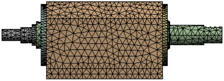
The specific FEM model of the spindle system.

Bearing largest preload with no more than 35°C temperature rise.
Bearing fatigue life analysis
After obtaining the contact angle data, the final calculation can be performed using the bearing fatigue life equation. The results of this are shown in Figure 12.
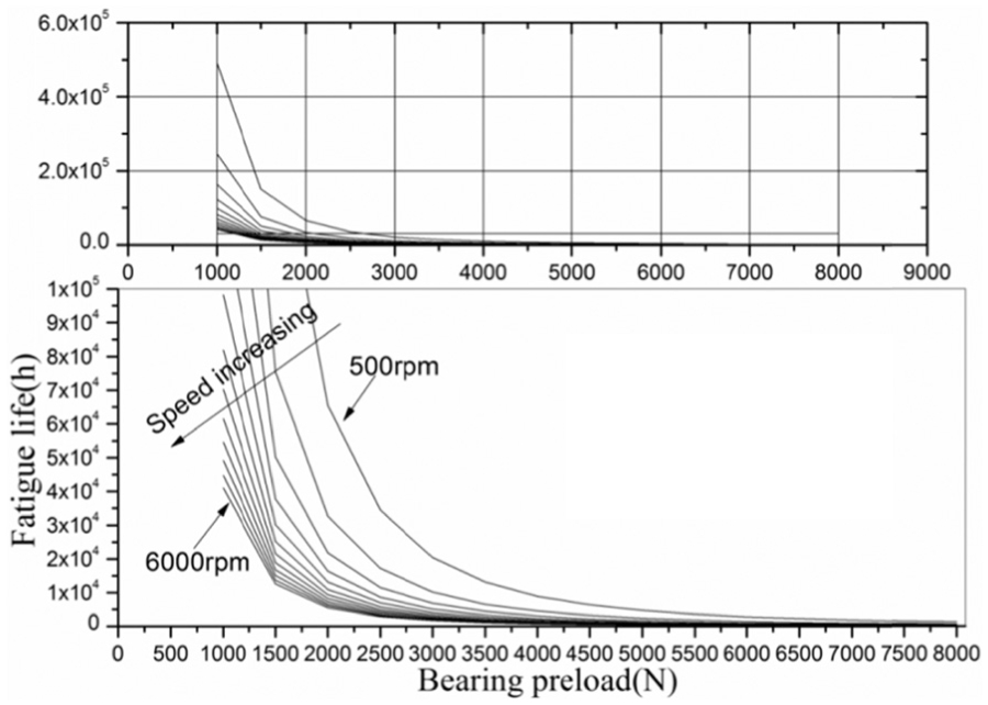
Bearing fatigue life versus bearing preload and spindle speed.
From Figure 12, it can be observed that the bearing fatigue life decreases dramatically with increasing spindle speed and bearing preload; the maximum value is over 500 times larger than the minimum value. The bearing fatigue life can be determined from the preload at different spindle speeds and compared to the normal operational life of machine tools, which is 8 h/day in 10 years.
Bearing ball skidding analysis
According to Hirano’s theory, the centrifugal force of the ball and the contact loads between the ball and the inner raceway are the critical factors for determining the bearing preload. Therefore, in this study, the relationships between these factors have been calculated based on internal load analysis of the bearing. The results are shown in Figures 13 and 14.
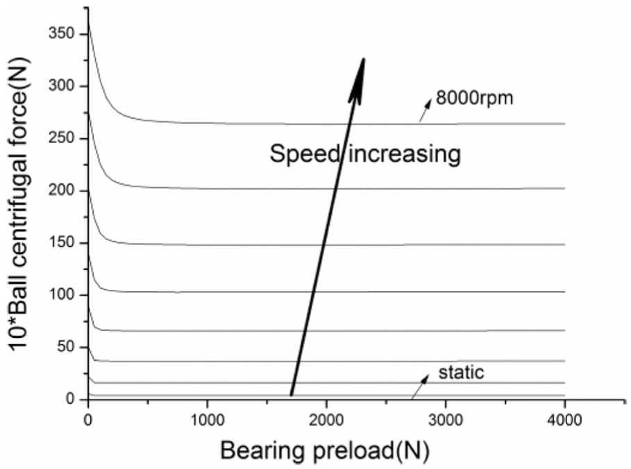
The 10× ball centrifugal force under different preload and speed.

The value of
From Figures 13 and 14, it can be observed that the centrifugal force of the ball tends to remain steady at different spindle speeds when the bearing preload is greater than 300 N. The value
From Figure 13, it may be seen that the 10× ball centrifugal force can be achieved with a bearing preload greater than 300 N. The bearing 10× ball centrifugal force with a bearing preload greater than 300 N is slightly dependent on bearing preload below a certain speed. At the same time, the

where n is the spindle speed, r/min.
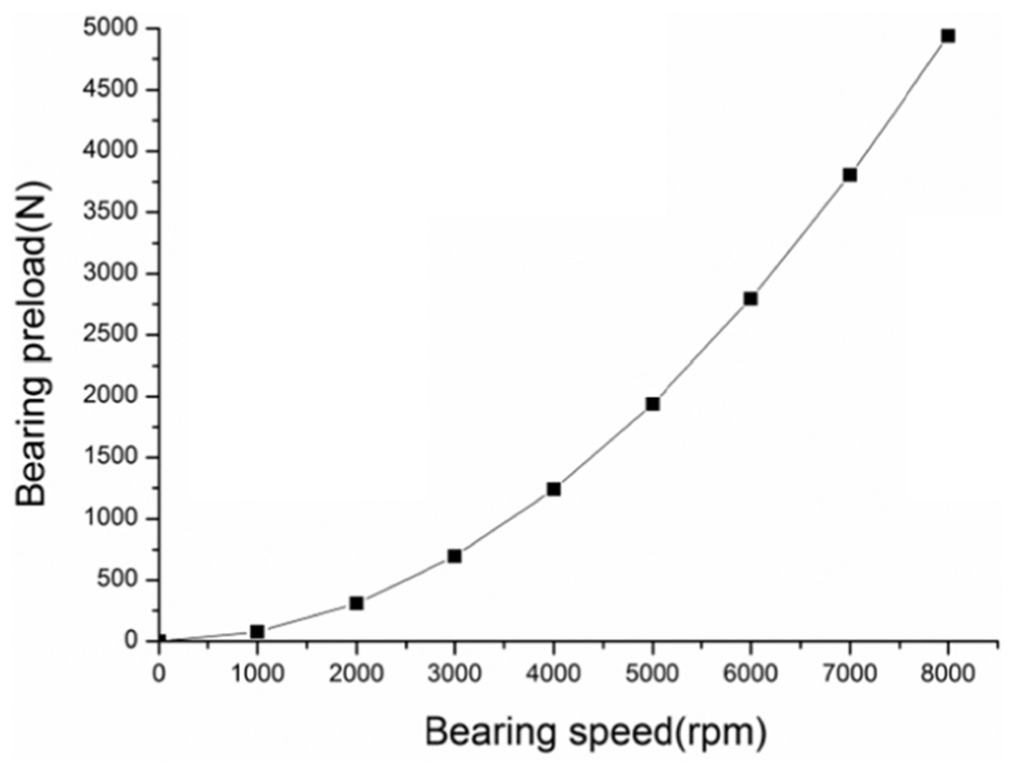
The optimal value for bearing preload based on ball skidding criterion.
Bearing preload determination and experiments
Determination of bearing preload
The above analyses show that the bearing preload is related to the factors that influence the running status of the bearing, which subsequently places a practical limit on the bearing preload.
Based on these analyses, the bearing preload acts as the key influence on the running state of the bearing and the spindle, and it is determined from the three parameters: bearing temperature rise, bearing fatigue life, and bearing ball skidding. Thus, the optimal combinations of values for applied bearing preload can be determined, which are shown in Figure 16.

Optimal conditions for applied bearing preload.
Measurement of bearing temperature rise
The FBG temperature sensors, which were all calibrated, were inserted into the spindle as well as glued to the bearing outer ring. Because each of the four bearings experiences the same conditions as the others at all times, only one bearing was monitored by the FBG sensors. The results are shown in Figure 17.

The bearing outer ring temperature rise under different spindle speeds.
Each experiment lasted over 3 h to ensure that the spindle system had attained a steady thermal state. From these figures, it is apparent that the spindle system bearing outer ring temperature rise has minimum value under a specific bearing preload which shows no difference with the calculated preload based on the ball skidding criteria. When the spindle bearing was subjected to no bearing preload, the bearing had severe ball skidding, and the bearing temperature rise was high; when the preload was applied on the bearing, the ball skidding was limited; however, when the bearing preload increased, the bearing generated heat also increased, so the bearing outer ring temperature was lifted; and when the ball skidding was vanished, the bearing temperature rise was held or decreased. Moreover, the drop point on the temperature rise curve is the optimum bearing preload to stop the ball skidding. The experimental results correlate well with the results of the simulation, verifying that the calculations and analysis are accurate. When the spindle rotates at 2000 r/min, the bearing preload to avoid the ball skidding is 300 N, and the experimental value is 500 N; at 3000 r/min, it is 700 N, and the experimental value is 750 N; at 4000 r/min, it is 1242 N, and the experimental value is 1250 N. The small gap between the analytical result and the experimental data at the spindle speed of 2000 r/min is caused by the increment in the bearing preload.
In addition, spindle stiffness is proportional to bearing stiffness, and the relationship between the bearing stiffness and preload can be observed in Figure 18, which illustrates that a larger bearing preload results in greater spindle stiffness. So far, the method employed in this article combines the bearing temperature rise, bearing fatigue life, ball skidding criterion, and the bearing stiffness.
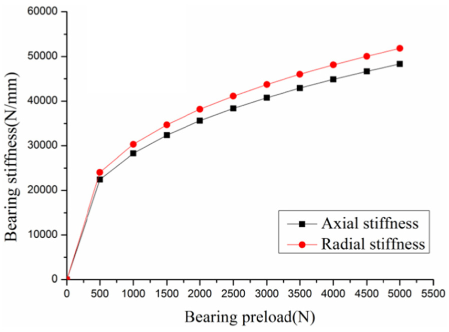
Bearing stiffness versus bearing preload.
Conclusion
Using internal load analysis of the spindle bearing, this article describes the relationships between the bearing preload and the bearing fatigue life, the bearing temperature rise, ball skidding, and spindle stiffness. These constitute the parameters that are most influential to the running state of the bearing and spindle system. Based on these relationships, this article provides an optimal range of bearing preloads, combining the bearing temperature rise, fatigue life, and bearing ball skidding. Experiments were conducted to verify the analysis. The results show that the analysis is consistent with the experimental results, indicating the analysis and the outcome of this study are reasonable. The bearing preload which can avoid the beating ball skidding can determine the minimum bearing preload; the relation between the bearing preload and bearing fatigue life limits the maximum bearing preload. The results summarized in this article have value in certain applications that require controlling machine tool thermal error and improving work accuracy.
Footnotes
Academic Editor: Murat Uzam
Declaration of conflicting interests
The author(s) declared no potential conflicts of interest with respect to the research, authorship, and/or publication of this article.
Funding
The author(s) disclosed receipt of the following financial support for the research, authorship, and/or publication of this article: The authors would like to acknowledge funding support from the National Natural Science Foundation Committee (NSFC) of China (grant no. 51475343) and International Science & Technology Cooperation Program of China (grant no. 2015DFA70340), as well as the contributions from all collaborators within the projects mentioned.