
Abstract
The passive exoskeleton with an automatic load-adapting mechanism is proposed in the article, which can assist people to do rehabilitation exercise and be used for the load carrying. The structure of the overall design is expounded in detail. In order to achieve a more efficient arrangement of space structure and to reduce the weight of the structure, a gas spring was selected as the passive energy actor. Furthermore, through effective design, the capability of automatic load-adapting was achieved in the structure. As the characteristics of the gas spring force will change with increasing elongation, curve fitting of the function to the gas spring force was achieved by the structural design. As a result, the performance of the exoskeleton was improved significantly after balancing.
Introduction
The exoskeleton robot is a wearable robot, 1 which is a system that combines human intelligence with the powerful athletic ability of robots. 2 At present, exoskeleton robots have been used in military, medical, and industrial applications, mainly to provide assistance to the wearer in power during rehabilitation. 3 The mass of the load that the human body can bear is limited, as is the duration that the human body can sustain the load. An exoskeleton can combine human intelligence with mechanical carrying capacity so that the wearer can carry a larger mass load without it feeling difficult. The exoskeleton can also replace the body, assisting the human in walking, and it can enhance rehabilitation for patients.4–7
Through improved structural design, the upper limb passive exoskeleton can compensate for the change in the potential energy in movement of the wearer’s upper limb, such that the user does not have to do work to overcome the potential energy and hence the burden on the body is reduced.
Active drives are widely used in exoskeletons. Motor-driven exoskeletons are listed as follows: MIT-Manus and ARM Guide8–10 at Massachusetts Institute of Technology, HAL made by University of Tsukuba, 11 CADEN-7, which was developed by Perry et al., 12 and the Balgrist University’s ARMin robot. 13 The following are pneumatic-drive exoskeleton: the pneumatically driven upper limb exoskeleton of Salford University, 10 RUPERT, which was made by He et al.;13–15 and BONES, 16 the pneumatically driven upper limb exoskeleton of Huazhong University of Science and Technology.17,18 The advantage of active drive is that it can support the multiple degrees of freedom of motion, but because of its power consumption and battery life, its load capacity is limited. The passive exoskeleton can balance the force in the direction of gravity and has a great advantage in the upper limbs primarily that the main load consumption is for vertical movement.
The upper limb exoskeleton, which was developed by the Universiteit Twente, the Technische Universiteit Delft, and the Northeastern University, transmits the angular load between the arm and the direction of gravity to the back via a link mechanism but also ensures freedom of the upper limbs. The balance spring is installed in the back of the exoskeleton, the elastic potential of which varies with angle between the arm and the direction of gravity so as to achieve the balance of the gravity potential of the human arm. 19 Carnegie Mellon University also has developed a very simple gravity-balanced upper limb exoskeleton named ‘ACRE’. ACRE uses a single-stage spring to balance the changes in the potential energy of the upper limb, and it is not completely fitted to the wearer’s arm but only has a connection at the end. The exoskeleton can be used to do rehabilitation training for sports injury patients at home. 20 The Scuola Superiore Sant’Anna has developed a gravity-balanced hybrid-driven exoskeleton, which uses a steel pulley to transmit the joint angle to the back via a multistage pulley. The error of the pulley envelope angle due to the angle change is compensated by the corresponding pulley mechanism. A rear rotation spring is used to carry out gravity compensation and achieve a gravity balance effect. At the same time, the drive mechanism is connected in series at the back to provide the power that is transmitted to the joints. 21
In addition to exoskeletons, the principle of gravity balance also has been applied in many robots. The gravity balance mechanism developed by the Delft University group can achieve a zero-work requirement in any position. 19 The University of Istanbul has developed a cam spring mechanism. It has the gravity balance ability and can be applied to robot arms. 22 Additionally, ZeroG, developed by Equipois, is an incomplete gravity balance mechanism, but the effect of gravity balance can reach more than 95%. 23
The spring is often regarded as the passive energy actor in the design of passive exoskeletons, but because of its low energy density, the problem will happen when the machine needs to have the heavy load support capability. In this study, a gas spring, which can significantly improve the energy density of the structure, was selected as the passive energy actor. According to its output properties, the curve fitting structure can be designed to ensure constant output. At the same time, its energy storage capability is developed, and the structure that can change loading ability automatically is designed to provide real-time balance of the load weight.
Methods
The main purpose of a passive upper limb exoskeleton is to offset the load that is produced by gravity on the load or the human upper limb. Differing from the spring balance principle, the gas spring belongs to a kind of approximately constant force spring. Thus, the linkage between the elastic force and gravity needs to be implemented in the exoskeleton structure. This relationship must have nothing to do with the angle of the arm; in this way, the transformation between the gravitational potential energy and elastic potential energy can be implemented during the arm rotation process. In this study, the structure is intended not only to produce a constant weight but also should be usable for flexible loads. Hence, the ability of the automatic linkage between the load mass and the structure adjustment needs to be implemented on the exoskeleton during the process of application.
Loading adapting passive joint design
According to the nature of the gas spring, as well as the main goal, the design principle is as follows.
Assuming that gravity is G, the force of the gas spring is F, the braced force in (c) is N, the overall structure is balanced in this state (Figure 1)


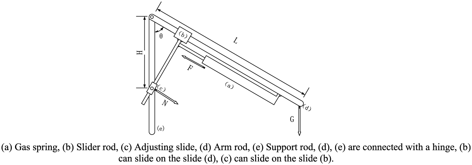
Design principle of the gas spring structure.
Substituting equation (1) in equation (2) yields

As illustrated in equation (3), the relationship between F and G is directly proportional. The equation has nothing to do with θ, so the balance of the mechanism can be implemented by adjusting the value of H. When H = 0, the location of (c) is adjusted to the position that overlaps with the hinge, and the gas spring does not afford any balance effect. When H is increasing, the ratio between F and G also is increasing and so does the ability of loading, thereby the ability of gravity compensation is achieved.
Optimization
The gas spring is regarded as a constant force spring in the design assumption, but the curve of the gas spring force is not a completely constant value during actual use as the force value will decrease with increasing elongation. If a better balance effect is to be achieved during movement, the adjustment needs to be implemented in the mechanical structure to increase the linearity of the output force.
The force curve of the gas spring needs to be obtained first. MASON 2600N gas spring is used in the experiment. Starting from 0 mm, with every 1 mm of elongation as a unit, then measuring the output, the relationship curve F(L1) between the output force F and the elongation L1 is shown in Figure 2.

Output force curve.
As illustrated in Figure 2, the output force of a gas spring is not an accurate constant value but is an approximate linear curve. It can be expressed as follows

then F0 is 2600 N, which is a constant value in the middle of the curve, and k1(L1) is the slope function.
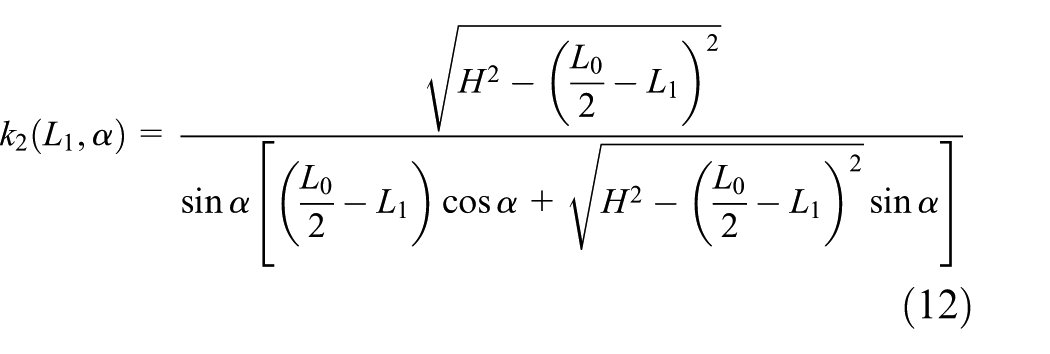
If it wants to ensure the establishment of equation (3), a function is needed to implement curve fitting. There is a direct relationship between the position and the angle in the structure, according to equations (3) and (4), assuming that

then k2(L1, α) is the function as needed.
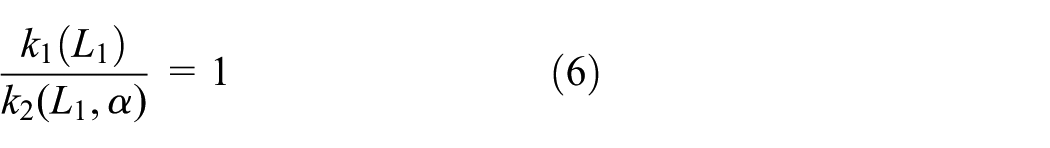
In order to optimize the gravity compensation effect, the equation must be satisfied
The construction of k2(L1, α) can be achieved by controlling the motor to change the H value, but this will lead to ceaseless changing of H under the condition of fixed bearing mass. The result not only brings a stability problem to the structure but also produces large amount of energy consumption. In this study, the function was implemented by the design of structure. It is equivalent to installing in series a variable stiffness connection on the end of the output force, and as a result, the force eventually effected on the structure is a constant value.
In order to meet the above conditions, the model described by Figure 1 has been adjusted, and the α parameter has been added.
Scrutinizing Figure 3


Modified cylinder arrangement.
Substituting equation (7) in equation (9) yields

It is thus evident that the introduction of the α angle makes the whole corresponding relationship into a function curve that is influenced by α. When α = 2/π, equation (3) can be obtained. It can be seen that the value of α determines the stiffness changes at the end of the gas spring. Thus, according to the actual output curve F(L1), the parameter α can be determined.
According to Figure 3, L0 is the total elongation of the gas spring, so the elongation

Combined with equation (5) yields
Because k1(L1) and k2(L1, α) cannot be exactly equal, using curve fitting the value of α can be obtained which can make equation (6) satisfied approximately.
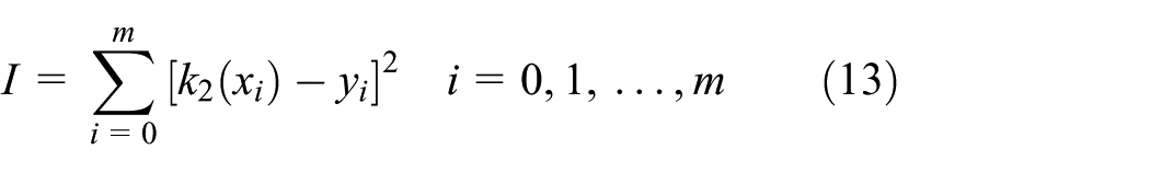
Equation (12) is a multiple function: a necessary condition for the existence of the minimum value is that the corresponding partial derivative is equal to zero. The purpose of the fitting is to obtain a suitable value of α, so

MATLAB software was used to do the calculation but when α = 96.12, Imin can be obtained. The fitted curve is in Figure 4.

Result of curve fitting.
It can be observed from Figure 4 now that k1(L1) and k2(L1, α) roughly coincide, that is, equation (6) is satisfied approximately. Substituting α into equation (10), the ratio of k1(L1) and k2(L1) can be drawn in Figure 5.
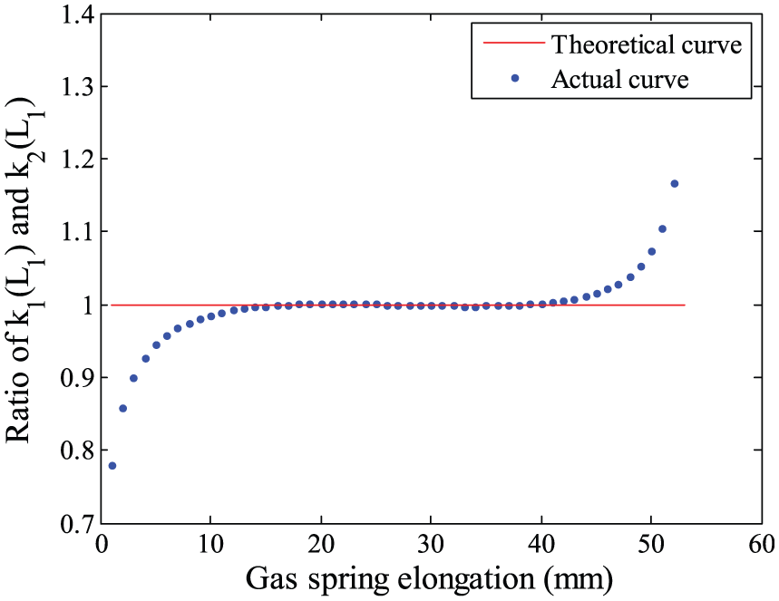
Actual curve of the loading mass G.
Scrutinizing Figure 5, the curve is a basic constant value. It illustrates that through the adjustment of the α angle, a good output force level has been obtained. In this way, it is possible to ensure the proportional relationship of equation (3) between the output force and the bearing weight. It can be seen from Figure 5 that when the elongation
As illustrated in Figure 2, H is proportional to gravity loading G; the value of H can be adjusted by motor automatically, so the capability of automatic load-adapting can be achieved in the structure. Otherwise, there is still a small deviation in the gravity loading G; in Figure 6, gray is the deviation zone. The deviation increases with the loading mass and is 0.73% of the loading mass.
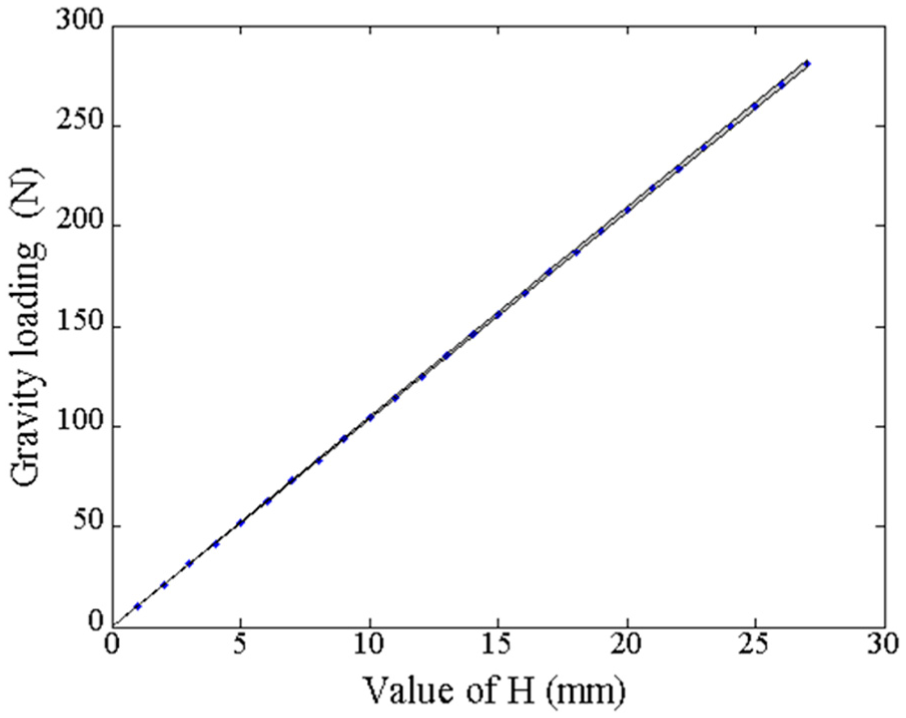
Theoretical optimization result.
Mechanism and simulation
Mechanism design
According to the above theoretical model, the upper arm structure can be designed based on the gas spring as the output device. Actually, this principle is used to achieve the transformation between elastic potential energy and gravitational potential energy, so this structure can only balance the force on the vertical axis. In the operation process, the whole structure can only have one-dimensional rotation. In order to ensure the accuracy of the balance, it is necessary to keep the support bar in a vertical state. Taking into account that the balance structures in both the upper arm and forearm are needed simultaneously, and the support rods for the both parts need to be in same direction, a parallelogram design was added in the structure in order to keep the support rods of two parts always parallel. Furthermore, the balanced part can only have a single-dimensional rotation. In order to achieve the above design, the degree of freedom is set as follows (Figure 7).

Overall structure of the exoskeleton.
According to the specific spatial structure, combined with the above design concept, the design of the internal structure is as shown in Figure 8.

Design of the internal structure.
As in the balance process of the upper arm and the forearm, the adjustment of the stiffness coefficient is basically in a symmetrical state. For a compact design concept, in the single arm, one motor is only set vertically in the elbow, adjusting the stiffness coefficient of the upper arm and the forearm synchronously. This can also reduce the mass of the exoskeleton, which is due to the weight of the motor. The overall mass of the passive upper limb exoskeleton was 12 kg and the maximum loading was 500 N.
Simulation
In order to prove the feasibility of the theory, the kinematics simulation of the model is carried out by Adams software. The resulting curve in Figure 2 is brought into the interaction force of the simulation, and mass block is set to 26 kg. Constant rotation is implemented to the joint in [−60°, 60°], and assist effect of mechanism is determined by the required torque of the joint hinge. Cases in no balance, α = 90 and α = 96.12, are simulated, respectively; the result is shown in Figure 9.

Result of the simulation.
It can be seen from Figure 9 that when there is no interact force, the maximum of active torque is 65 N m; when the interact force exists, the maximum of active torques in α = 90 and α = 96.12 are 3.96 and 0.21 N m, respectively. The application of gravity balance greatly reduces the output value of the active joint torque. Contrasting α = 90 and α = 96.12, it is obvious that the effect of gravity balance is optimized. The simulation results show that the structure can achieve a good balance in gravity.
Experiment
Adjustment of the balance structure is actioned by the motors, which are installed on the both arms. The main purpose is to achieve that the motor can accurately drive the screw nut to adjust the balance of the structure. Closed-loop control is managed mainly by the sensor(s) on the exoskeleton. The pressure sensors (to measure the mass of the weight) are equipped in both hands of the exoskeleton, which is used in the closed loop to identify the loading mass. Then, position of the motor is controlled to achieve the dynamic adjustment of H value. The experimental platform is built in order to verify the performance of the structure, and single arm balance test is carried out. For proving the feasibility of the system, the experiment is implemented by hanging the load at the end of the hand. In this method, the balance performance can be seen more intuitively. Figure 10 is the experiment platform.

Experiment platform.
In order to test gravity balance ability, calibration test is implemented. The experiment is in the form of loading mass gradually; by the adjustment of motor, the H value can be measured when the balance has been achieved. As illustrated in Figure 2, when θ = 90°, the deviation reaches the minimum, so θ = 90° has been selected as initial condition. The starting mass is 0 kg, the increment step is 2 kg; until 20 kg, we collect five sets of data at each node. The resulting data are plotted in Figure 11.

Actual measurement value.
Scrutinizing Figure 11, the curve of big arm and forearm is parallel, and the slope is consistent with the calculated results in Figure 6. But by comparison, it can be seen that abscissa value of two curves have increased, and the changing in big arm is 2.88 mm more than forearm. This because the exoskeleton has its own weight, and the weight bore by big arm is more than it bore by forearm. Therefore, according to this initial condition, big arm and forearm need to be preadjusted to the appropriate balance position. In addition, due to the existence of friction in the structure, each measurement will be slightly different but also it is a main reason that causes the difference between Figures 6 and 11.
Automatic load-adapting experiment has been implemented based on the data in Figure 11. The mass of the load is 20 kg, and Figures 12 and 13 mainly show the structure balance status in four positions when the exoskeleton is max loading and zero loading. It can be seen from the experiment that in the zero loading state, the arm can be stationary in different angles. When the operator performs the loading action, through the automatic adjustment, the arm can achieve a new balance with the load. In the experiment, gravity balance status will become slightly worse when θ = 60° and θ = 120°. According to Figures 5 and 6, the maximum of deviation is just in these two angles, so slight instability will occur sometime in the actual operation. The experiment can prove that the passive mechanism has a good ability to balance the load in the direction of the gravity and can change its load ability automatically.

No load experiment.

Full load experiment.
Conclusion
In this study, the passive exoskeleton with an automatic load-adapting mechanism is proposed. Compared to previous structures, the design method of utilizing a gas spring can increase the density of the energy and improves the structure in that it keeps it compact, so that the exoskeleton has a greater load capacity. Real-time balance of gravity can be facilitated by the combination of motors and the gas spring. In the application, this upper limb exoskeleton can be used for load carrying or rehabilitation. When used as a load carrier, it is necessary to set an appropriate loading range and the hand structure for specialized use; when used for rehabilitation exercise, the load ability and the mechanical structure size should be relatively reduced because the body arm will regard as the load. The content of this article belongs to the principle research, so the design for more specific situations will be the next steps in the research program.
Footnotes
Academic Editor: Francesco Aggogeri
Declaration of conflicting interests
The author(s) declared no potential conflicts of interest with respect to the research, authorship, and/or publication of this article.
Funding
The author(s) disclosed receipt of the following financial support for the research, authorship, and/or publication of this article: The study was supported by National Key Research and Development Program (Grant: 2016YFC0800607); National Nature Science Foundation of China (U1613219); Project supported by the Foundation for Innovative Research Groups of the National Natural Science Foundation of China (Grant no. 51521003).