
Abstract
In the task of carrying heavy objects, it is easy to cause back injuries and other musculoskeletal diseases. Although wearable robots are designed to reduce this danger, most existing exoskeletons use high-stiffness mechanisms, which are beneficial to load-bearing conduction, but this restricts the natural movement of the human body, thereby causing ergonomic risks. This article proposes a back exoskeleton composed of multiple elastic spherical hinges inspired by the biological spine. This spine exoskeleton can assist in the process of bending the body and ensure flexibility. We deduced the kinematics model of this mechanism and established an analytical biomechanical model of human–robot interaction. The mechanism of joint assistance of the spine exoskeleton was discussed, and experiments were conducted to verify the flexibility of the spine exoskeleton and the effectiveness of the assistance during bending.
Keywords
Introduction
Low-back pain (LBP) affects a large part of the working population. The compression force of the lumbosacral (L5/S1) joint has been identified as one of the most prominent risk factors for LBP. 1 It is found that there is a strong correlation between the compression force of the lumbar spine and the torque around the L5/S1 joint. 2 Although the use of cranes or balancers can prevent back injuries, 3 they are rarely used in workshops with human load capacity or limited space. 4 So another possibility to reduce the mechanical load on the lower back is to use an exoskeleton.
In the past few decades, several passive back support exoskeletons have been proposed. These devices can be roughly divided into two categories: soft coats and hard exoskeletons. The soft jacket transmits force through tensile structures, such as the personal lift augmentation device (PLAD) 5 and the smart suit light. 6 Rigid exoskeleton can use rigid structure to conduct force, such as wearable torque recovery device, 7 bending nondemand return, 8 and Laevo. 9 The flexible exoskeleton has advantages in terms of the comfort of human movement, while the rigid exoskeleton has a more prominent conduction effect on the load.
The back device is an important part of the exoskeleton robot, designed to reduce the load acting on the human spine, thereby reducing the mechanical damage of the human back. Most back exoskeletons and most back devices are usually rigid, 10 which restricts the movement of the wearer’s torso 11 but is beneficial for rehabilitation. For industrial applications, a wide range of motion and versatility are particularly required. Research on the exoskeleton spine mostly focuses on the back supporting exoskeleton. To maximize its versatility, Taal and Sankai 10 designed an exoskeleton spine and conducted preliminary tests, which showed that the wearer can move all the degrees of freedom of his spine and shoulder straps. Näf et al. 12 designed a passive bionic exoskeleton and performed modeling and preliminary prototype tests on it, which has a large range of motion. Yang et al. 13 developed a continuous soft exoskeleton that conforms to human anatomy and can reduce a variety of forces along the human spine. These studies show that a low stiffness exoskeleton can improve the comfort of human wear but reducing the stiffness of the exoskeleton will sacrifice the ability to conduct load. Therefore, the stiffness of the exoskeleton is very important, especially in the design of the passive exoskeleton.
The back exoskeleton can be used to assist the back during the bending process of the human body, so as to reduce the fatigue of the human back. Abdoli et al. developed a prototype of a PLAD 4,14,15,16 which can reduce the required waist bending moment by 20% to 30%, without negatively affecting other joints or lifting exercises. Takayuki et al. 17 developed an unpowered auxiliary supporter Smart Suit Lite, and experiments have shown that the user’s backload during nursing work has been reduced. Näf et al. 18 proposed a new type of passive back support exoskeleton, which can perform a large range of motion when worn and provides up to 25 Nm of support torque on the lower back. Yang et al. 19 proposed a Bowden-driven flexible spine exoskeleton for back support during the bending and lifting process. The back exoskeleton can also be used to conduct load transmission to the back of heavy objects, reducing the load effect of heavy objects on the human body. Park et al. 20,21 designed a spinal exoskeleton for human body weight-bearing, and the length of the exoskeleton can be actively adjusted to adjust the shoulder’s state. The back exoskeleton can exert a boosting effect during the bending process and the weight-bearing movement of the human body, and the design of the exoskeleton has different effects on the performance of these two functions.
For the weight-bearing exoskeleton, the back device must be able to transmit loads and ensure the range of motion of the wearer’s torso. For healthy wearers, in the industrial field, a wide range of motion and versatility are particularly required. To overcome these limitations, we designed a rigid–flexible coupled passive bionic spine exoskeleton, performed a movement analysis on the exoskeleton spine, and studied the torque and tension changes of the joints of the exoskeleton spine during the bending motion of the human body. Experiments have verified the flexibility of the spinal exoskeleton and the effectiveness of assisting in the process of bending.
Spine exoskeleton prototype design
In the industrial environment, the large-scale movement of the spine facilitates workers to perform different tasks without restriction. Excessive restriction of the exoskeleton on the human body may cause safety problems, as workers may lose their balance. 19 By introducing the external spine, the entire range of motion of the lumbar spine can be fully utilized. The external spine design requires the wearer to transfer the backload and reduce the burden on the back spine, including the weight-bearing situation when the upper limbs are upright and the waist bending process when lifting heavy objects, as shown in Figures 1(b) and 2. The assist mechanism of the spinal exoskeleton in this design during bending is not related to the hip joint. The exoskeleton that distinguishes the hip joint and the lumbar joint support can be used to evaluate the peak and cumulative load of the back.

The design of the spinal exoskeleton. The spinal exoskeleton includes caudal joints①, lumbar joints②③④, and thoracic joints ⑤⑥⑦. In the initial state, the ball joint rod in each vertebral body unit is compressed in the ball socket under the action of the spring. (a) Biological model of the human spine, (b) how to wear spinal exoskeleton, and (c) design of the spinal exoskeleton.

The degree of freedom of movement of the vertebral body unit of the spine exoskeleton. (a) The bending angle α of the vertebral body unit in the sagittal plane around the x-axis, (b) the bending angle
Generally, for the back support exoskeleton, full support is not required. Because, the full support of the load means the high rigidity of the structure, which will cause high human–robot interaction and discomfort for the wearer. 20 Another problem is that if too much support is provided, the back muscles will degenerate. Therefore, the existing exoskeleton and outerwear are usually designed to obtain up to 30% support. 4 The exoskeleton spine should be able to follow the movement of the wearer’s torso and reduce the constraints on the wearer’s back. The high-rigidity exoskeleton is not conducive to the comfort of human–robot interaction, so this solution needs to use elastic elements to adjust the stiffness of the exoskeleton to improve the flexibility of the human body when wearing it.
The human spine is located in the center of the back, the upper end of the spine supports the skull, and the thoracic segment is connected with the ribs and sternum to form a bony thorax. 22 Inspired by the structure of the human spine in Figure 1(a), the spinal exoskeleton design is shown in Figure 1(b) and (c). The spinal exoskeleton is connected to the shoulders of the human body by means of straps on the wearer. Its bottom can be connected with the exoskeleton of the lower limbs to facilitate the transmission of the weight of the upper limbs to the ground. Analogous to the multijoint structure of the human spine, the spine exoskeleton contains three thoracic joints, three lumbar joints, and one caudal joint, and seven vertebral body units are connected end to end.
Each vertebral unit includes a ball hinge mechanism and a spring. In the initial state, the ball joint rod in each vertebral body unit is compressed in the ball socket by the spring, so the initial state of the spinal exoskeleton is straight, as shown in Figure 1(c). Each vertebral unit has four degrees of freedom. With the action of external force, each ball joint can realize the freedom of rotation around three coordinate axes and the freedom of movement in the direction of spine elongation, as shown in Figure 2. The sagittal plane of the vertebral unit bends around the x-axis can meet the movement needs of the human body in the forward and backward bending process. The coronal unit of the cone unit is bent around the y-axis can meet the movement needs of the human waist during the lateral bending process. The cone unit rotating the horizontal plane around the z-axis can meet the horizontal rotation of the upper body of the human body. Since the shoulder of the exoskeleton is fixed to the shoulder of the human body, the extension of the vertebral body unit along the z-axis can meet the requirements of the back surface extension when the human body is bent forward.
The internal parts of the vertebral unit are made of titanium alloy to bear the force and load, and the outer shell is made of resin material to reduce the mass of the exoskeleton. A composite elastic rope is used between the vertebral units to maintain the initial state of the exoskeleton. This is inspired by the trapezius muscle and quadratus lumborum muscle of the human back. The composite elastic rope is a composite material composed of a metal spring and a rubber layer, as shown in Figure 1(c).
Modeling and analysis of spinal exoskeleton
The motion state of the vertebral unit during the bending of human body
There are two stages in the human body bending process: the first stage is the process from an upright state to a small degree of bending. As shown in Figure 4, in each unit of the spine exoskeleton, only the angle between the spherical hinge block and the spherical block changes. In the second stage, as shown in Figure 5, with the bending angle of the human back increases, each unit of the spinal exoskeleton breaks away from the spherical block and the entire length of the spinal exoskeleton is extended.
When the human body bends over and lifts a heavy object, the motion form of the vertebral body unit of the spinal exoskeleton is a combination of twisting and stretching. Figure 3 is an interactive model when the human body wears the spinal exoskeleton to carry objects. The spine exoskeleton is connected to the waist of the lower extremity exoskeleton. The upper end of the spine exoskeleton has a boosting effect on the human shoulder. The force

Human–robot interaction model of spine exoskeleton in human body bending and transportation tasks.

where
Bent joint—The ball head is in the socket
Due to the existence of the compression spring, the initial state of the exoskeleton vertebral body unit is that the ball head is in the ball socket, and the vertebral body unit of the exoskeleton bends with the bend motion of the wearer. In this movement mode, the ball head coincides with the ball center of the ball socket, and the state of the vertebral body joints of the spinal exoskeleton is shown in Figure 4.

Exoskeleton joint unit state 1—Bending.
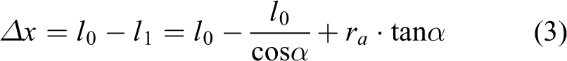
The initial length of the spring is l 0 0, when the joint deflection angle is α and the length of the spring l 1 1 is as follows

where Ra is the radius of the connecting rod head, which is equal to the radius of the spring.
Then the deformation of the spring
According to the model in Figure 3, the spring compression force
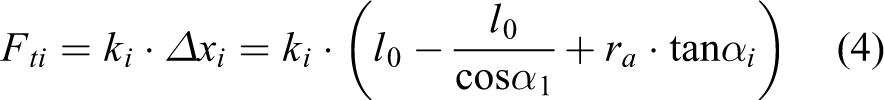
where ki
is the spring stiffness of the ith joint,
Then the torque Mi provided by each joint is as follows

The critical point of the ball head out of the socket
As shown in Figure 4, when the end of the ball head output rod in the vertebral body joint module is against the upper cover, the torsion angle of the ball head rod in the ball socket reaches the maximum. If you continue to increase the bending angle, the ball head will be connected. The rod leaves the socket. Therefore, the bending angle of the vertebral body joint ball joint rod end when it abuts the upper cover plate can be regarded as the critical point.
Critical angle

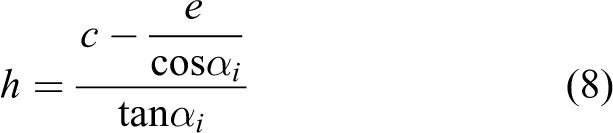
where c is the radius of the upper joint plate openings, e is the radius of the ball link of the output shaft, and d is the joint plate thickness.
Joint elongation—The ball head out of the socket
When the bending angle of the vertebral body unit is greater than the critical angle

Exoskeleton joint unit state 2—Stretch.
Similarly, when the joint deflection angle is α and the distance between the center of the sphere and the upper-end cover surface is h, the length of the spring l 1 is as follows
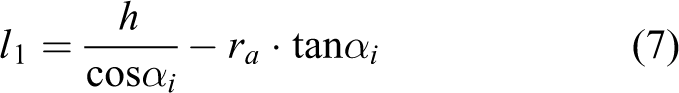
The amount of deformation of each spring
The force produced by each spring compression

The output force of the spine exoskeleton
Model the overall mechanism of the exoskeleton and analyze the effect of the spine exoskeleton on the human body during the bending process.
The effect of the exoskeleton on the human body only when the torque is generated by the torsion of the joints
The model analysis of the end of the spine exoskeleton (joint 7) is shown in Figure 6(b), and the balanced relationship is as follows


where

Kinematics analysis of spinal exoskeleton: (a) kinematics modeling of the spinal exoskeleton, (b) force analysis of joint 7 when vertebral body joints are only rotated, (c) force analysis of joint 6 when vertebral body joints are only rotated, (D) analysis of the force on joint 7 when the vertebral body joint is only stretched, (e) analysis of the force on joint 6 when the vertebral body joint is only stretched, (f) when the vertebral body joint is balanced by gravity, the force on joint 7 is force analysis, and (g) force analysis of joint 6 when the vertebral body joint balances gravity.
Analyze the balance state of joint 6, as shown in Figure 6(c)


where
Combining Eqs. (13) and (16), the forces
Only consider the force of the exoskeleton on the human body when the joints produce tension
The force analysis of the exoskeleton end joint is shown in Figure 6(d)


where
Then the force analysis of each joint is shown in Figure 6(e), the force balance equation of the connecting rod between the two joints is as follows


where
Joint stiffness
The stiffness of the joints in the vertebral body of the spine exoskeleton is very important to the performance of the exoskeleton. The minimum requirement for the stiffness of the joints is to compensate for the gravity of the spine.
The analysis of joint 7 is shown in Figure 6(f), and the torque of joint 7 M 7 is as follows

The analysis of joint 6 is shown in Figure 6(g), and the torque of joint 6 M 6 is as follows

Then the torque Mi in the balance of any joint is as follows

Combining Eqs. (4) and (25), substituting the collected torsion angles of human joints, the stiffness of each joint when the spine exoskeleton is at the maximum bending angle of the human back is calculated as
Design parameters of joint stiffness of spine exoskeleton.

Experiments and results
Exoskeleton joint output force test
The vertebral body joint of the spine exoskeleton is fixed on the experimental table, and the direction of the electric slide rail consistent with the bending direction of the vertebral body joint is kept. One end of the tension sensor (GY-SB, China) is fixed on the slider, and the other end is fixed to the output end of the vertebral body joint by a wire rope. The linear encoder is used to measure the displacement of the slider. The experimental scene is shown in Figure 7.

(a) and (b) Spinal exoskeleton joint test experiment.
During the experiment, under the drive of the electric sliding table, the output end of the vertebral body joint was deflected from the initial state (0°), the data of the tension sensor and the linear encoder were recorded, and each vertebral body joint was tested 10 times. The rotation angle

Taking joint 5 as an example, the corresponding relationship between the output force of the spinal exoskeleton vertebral joint and the bending angle is shown in Figure 8.

Output force data of spine exoskeleton joint 5.
The joint begins to bend under the action of external force in the initial state (0°), and the force at the output end of the single joint becomes larger as the bending angle becomes larger. It can be seen that there is an inflection point in the output force when the joint is bent about 25°, here is the maximum angle of the ball joint rod rotating in the ball socket. When the traction output end is continued to move beyond this critical angle, the ball joint rod separates from the ball socket rod, and the output of the joint is tilted pulling force at this time. The ball head needs a large external force to break away from the ball socket, which is caused by the friction between the ball head and the socket. It can be seen from the experimental results that the maximum output torque in the torsion stage is 1.2 Nm, and the maximum torque generated in the elongation stage is 2.7 Nm. There is no force data in the initial start-up phase, which may be caused by the wire rope between the force sensor and the joint output terminal not being in a tight state.
Experiment of human body wearing spinal exoskeleton
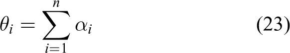
Three healthy subjects wore spinal exoskeleton tests. This study was approved by the Institutional Review Board of Xi’an Jiaotong University, and informed written consent was obtained from all subjects. The age of the subjects ranged from 20 years to 32 years, the height ranged from 165 cm to 178 cm, and the weight ranged from 52 kg to 74 kg. The subject wears a spinal exoskeleton and marks each segment of the spinal exoskeleton. To maximize the performance of the spinal exoskeleton, the subject wears an unpowered exoskeleton on the lower limbs, and the two exoskeletons are connected at the waist. As shown in Figure 9(a), the Vicon 3D motion capture system collects the movement trajectory of the exoskeleton.
(a) to (f) Spinal exoskeleton wearing experiment.
Degrees of freedom of the spine exoskeleton
The upper body of the wearer performs sagittal bending, coronal scoliosis, and horizontal twisting exercises, as shown in Figure 9(d) to (f). The subjects performed 3 groups of experiments, each group exercised 10 times to test the range of motion of the exoskeleton in each degree of freedom.
As presented in Table 2, the spinal exoskeleton can follow the three degrees of freedom of the upper limbs in the sagittal plane, coronal plane, and horizontal plane rotation, and the range of motion is within the range of human motion. The exoskeleton movement limit can give the wearer of performing tasks. Time brings safety and security.
The range of motion of the spinal exoskeleton.

Position changes between exoskeleton vertebrae during bending
To obtain the relative position change data between the various vertebral bodies during the bending process of the human body wearing the spinal exoskeleton, the subject wears the spinal exoskeleton and bends to the greatest extent, as shown in Figure 9(d). The subjects performed three sets of experiments, and each set of experiments was done to bend over 10 times to the maximum.
The task of transport is to bend over in the sagittal plane. As the exoskeleton of the spine is bent over with the human body, the bending angle of each vertebral body joint of the spine is shown in Figure 10. It can be seen that the bending angle

The bending angle of each joint of the exoskeleton during bending.
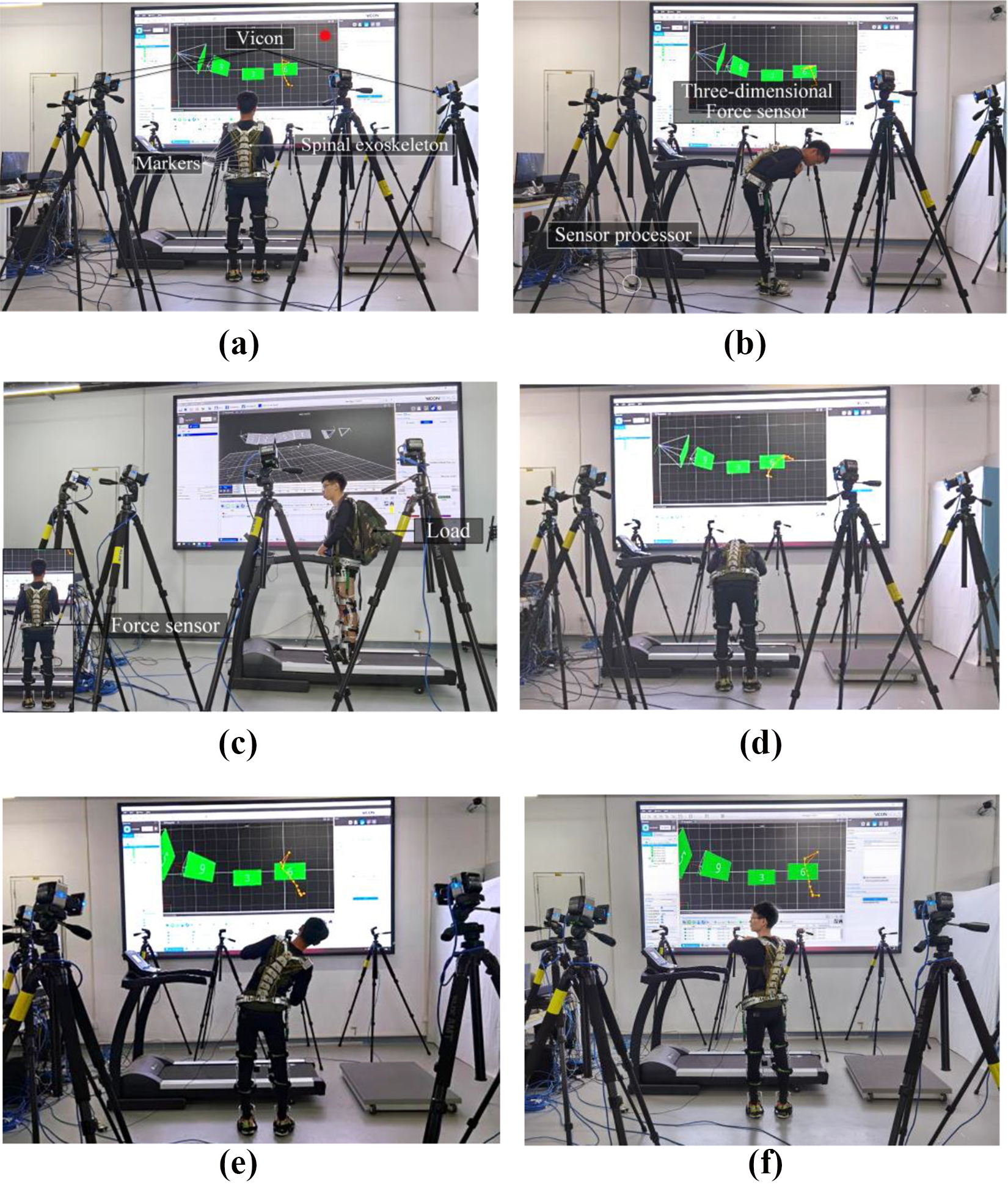
The relationship between the stretching distance between the joints and the bending angle of the back during bending is shown in Figure 11. It can be seen that the stretching amount of each joint increases with the increase of the bending angle of the human body. Joint 1 has the largest stretch, which is close to 30 mm. The stretch of each joint of the spinal exoskeleton gradually decreases from bottom to top, and the stretch of joint 7 is almost zero. The reason why the initial length of each joint is different may be that the marking points are not accurately and equidistantly placed on the joints.
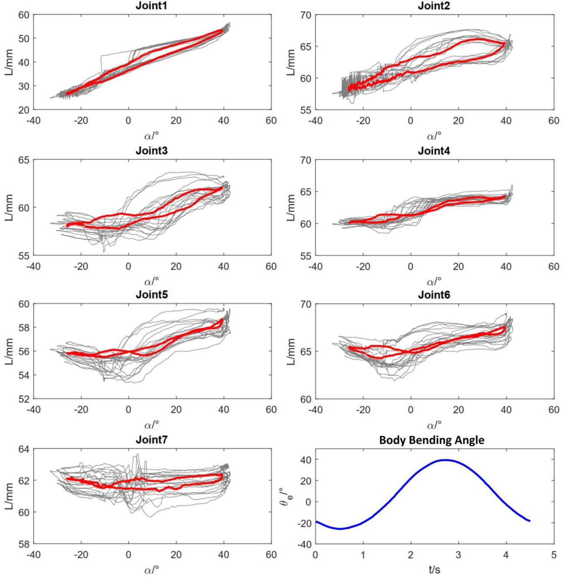
The length of each joint of the exoskeleton during bending.
The assisting effect of the exoskeleton on the human body during bending
Connect the three-dimensional force sensor (EPIC, China) in series between the top joints of the spine and connect the force sensor and Vicon to the data synchronizer, as shown in Figure 9(b). The subjects performed three sets of experiments, and each set of experiments was done to bend over 10 times to the maximum.
The experimentally measured force data of the end of the spine exoskeleton (shoulder) on the human body is shown in Figure 12. It can be seen that the force generated by joint stretching is greater than the force generated by bending. The maximum force

The force of the exoskeleton end on the human body during bending.
The dotted line is the value calculated by the joint angle change data of Figure 10 and the joint elongation data of Figure 11. The actual measured force is less than the calculated value. The reason may be that the spinal exoskeleton does not achieve the best matching effect on the human body, for example, the initial length is too large. Relaxation; similarly, the friction of the spinal joints is also one of the possible causes.
Weight-bearing test
The spinal exoskeleton, as a part of the booster exoskeleton, should have the ability to conduct loads. Although the previous article is designed around the carrying capacity of the spinal exoskeleton, here we test the weight-bearing performance of the spinal exoskeleton. The subject wears a spine exoskeleton and carries a backpack. A weight of 0–40 kg is placed in the backpack, increasing by 5 kg each time. The pressure sensor (GY-SB) was connected in series to the bottom of the spine (near the waist with the fingers), and the subject remained standing to test the weight-bearing capacity of the spinal exoskeleton in a static state, as shown in Figure 9(c).
The static weight-bearing capacity of the spinal exoskeleton is shown in Figure 13. The force conducted by the exoskeleton increases with the increase of the load, and the wearing efficiency is above 55%, which proves that the spinal exoskeleton can effectively conduct the load on the wearer’s back.

(a) and (b) The exoskeleton’s weight-bearing performance.
Discussion and conclusions
To protect the wearer’s back during handling tasks, this article proposes a back exoskeleton composed of multiple elastic spherical hinges inspired by the biological spine. The exoskeleton is composed of seven passive elastic joints connected end to end, which can ensure flexibility and provide assistance during the bending process of the human body. Each joint of the spinal exoskeleton has four degrees of freedom and has two force output modes: twisting and stretching. We deduced the kinematics model of this mechanism and established an analytical biomechanical model of human–computer interaction.
The spring stiffness of the vertebral body gradually increases from bottom to top. The maximum output torque of the minimum stiffness vertebral body joint in the torsion phase is 1.2 Nm, and the maximum torque generated in the elongation phase is 2.7 Nm, which is smaller than the two vertebral bodies with the same nonpower design. The torque is 3.6 Nm, 12 because we show the joint parameters with the smallest stiffness, other joint stiffnesses are listed in Table 1. The waist of the spinal exoskeleton can be assembled with other exoskeletons of the lower limbs, which helps the spinal exoskeleton play a boosting effect when the waist is bent and is also convenient for the negative gravity transmission of the spinal exoskeleton. The fully flexible back of the exoskeleton 14,18 cannot support the load when it is upright. And compared with the back structure of the powered exoskeleton, 20 the structure of the unpowered exoskeleton spine is lighter.
The subject wore the spinal exoskeleton. In the bending experiment, the spinal exoskeleton can provide up to 31 N boost to the upper back, which is less than the boost effect of the back boost exoskeleton in ref., 14 because the prototype designed in this study is being tested, It is installed on the unpowered exoskeleton of the lower extremity and does not include hip joint assistance. And the elastic beam on the back of the exoskeleton in ref. 14 cannot conduct load. Wearing experiments verified the flexibility of the spinal exoskeleton and the effectiveness of assisting in the process of bending. Although there is no calculation for the weight-bearing function of the exoskeleton in the design, the experiment proved the feasibility of the spinal exoskeleton to conduct the load in the static state. This spine exoskeleton has not yet considered the adjustment design for subjects of different heights and body types, so subjects with lower heights have no assistive effect during the anterior process of bending. The taller subjects are affected by the deformation process of the exoskeleton and cannot bend completely to the maximum extent. In the future, we will consider designing adjustable size mechanisms for subjects of different heights and body types to accommodate more wearers.
In this research, we initially obtained the power-assisted mechanism of the human body in the process of carrying heavy objects and the power-assisted model of the multilink spine exoskeleton, which is of great help to the follow-up research. Although the spine exoskeleton has a certain back-assisting ability, it is far from enough for realizing large-load handling and weight-bearing assistance. Although we can increase the stiffness of the spring to increase the boosting effect of the exoskeleton on the human back, this will reduce comfort. And long-term use will reduce the spring stiffness coefficient and reduce the boost efficiency. In future work, we can still use this solution, increase the human hip assist mechanism, and change the spine to an active drive mode, and control the movement of the exoskeleton according to the intention of the human body, which is very useful for heavy load handling tasks necessary.
Footnotes
Author contributions
Conceptualization: JS and AZ; methodology: YT; software: JS; validation: JS; writing—original draft preparation: JS; writing—review and editing: AZ; visualization: JZ; supervision: AZ; and project administration: AZ.
Authors Note
Aibin Zhu is also affiliated from Shaanxi Key Laboratory of Intelligent Robots, Xi’an, China.
Declaration of conflicting interests
All subjects gave their informed consent for inclusion before they participated in the study. The study was conducted in accordance with the Declaration of Helsinki, and the protocol was approved by the Bioethics Ethics Committee of Xi’an Jiaotong University (Protocol 2019-1215).
Funding
The author(s) disclosed receipt of the following financial support for the research, authorship, and/or publication of this article: This research was funded by the National Natural Science Foundation of China (No. U1813212, 52175061), Shaanxi Provincial Key R&D Program (2020GXLH-Y-007, 2021GY-333, 2021GY-286, 2020GY-207), Shanxi Provincial Key Research Project (2020XXX001), Xinjiang Funded by Autonomous Region Major Science and Technology Special Project (2021A02002).