
Abstract
Load-carrying exoskeletons need to cope with load variations, outside disturbances, and other uncertainties. This paper proposes an adaptive trajectory tracking control scheme for the load-carrying exoskeleton. The method is mainly composed of a computed torque controller and a fuzzy cerebellar model articulation controller. The fuzzy cerebellar model articulation controller is used to approximate model inaccuracies and load variations, and the computed torque controller deals with tracking errors. Simulations of an exoskeleton in squatting movements with model parameter changes and load variations are carried out, respectively. The results show a precise tracking response and high uncertainties toleration of the proposed method.
Keywords
Introduction
The exoskeleton is a kind of wearable and anthropomorphic device that enhances the physical capabilities of a non-disabled wearer.1,2 It looks like a humanoid robot or a part of that in appearance and is worn in parallel with human body in general. The significant feature of the mechanical device is that it combines the cognitive ability of human with powerful mechanical system, 3 which makes the human–machine system more intelligent and powerful. For example, lower limb exoskeleton can adapt complex terrains well without building map in advance. 4 Load-carrying exoskeleton (also called load-bearing or load transfer exoskeleton) is one kind of lower limb exoskeletons. It transfers substantial loads to the ground directly rather than augments human joints power. 1 This type of leg exoskeleton is urgently needed in the military for long-distance locomotion with heavy loads 5 and is widely researched during the past two decades. However, one of the most difficult problems in designing an excellent load-carrying exoskeleton is the control system. On the one hand, the device should follow the pilot’s motion flexibly. On the other hand, it should overcome load variation and other disturbances and support the remainder loads steady at the same time. In most cases, the carried loads could be a few times heavier than the device itself, and the variation of loads is a tough challenge for control system design.
Much work has been done on the control of load-carrying exoskeleton by earlier studies. But most of them deal with fixed payload or small load variation, or only focus on the uncertainty of the dynamic model. Among them, more effective and practical methods include sensitivity amplification control (SAC), model-based control (MBC), sliding mode control (SMC), and neural network-based adaptive control (NNAC). The Berkeley Lower Extremity Exoskeleton (BLEEX) is the first functional load-carrying activated exoskeleton. It uses SAC method to acquire a high sensitivity of pilot’s forces or torques without any human side information, which is hard to be measured accurately.4,6 But the control method depends on a better dynamic model and is unable to cope with parameter variations and model uncertainties. After BLEEX, SAC is seldom being used in other exoskeletons for its strick requirements of the model. MBC, such as direct force control7,8 and impedance control,9,10 is relatively easy to implement. HEXAR-CR50 developed by Hanyang University uses direct force control to calculate the desired joint torques in the stance phase and then applied a proportional–integral–derivative (PID) controller at each joint.11,12 The exoskeleton developed by Massachusetts Institute of Technology (MIT) uses similar force control method under a state-machine control strategy with the support of plenty of sensor information. 13 Both of them showed wearer’s metabolism reduction during locomotion.
To enhance the robustness of the exoskeleton control system, SMC 14 and intelligent control NNAC 15 are mainly investigated. SMC has an advantage of parameter-insensitive, and NNAC is good at approximating uncertainties. Hence, the method of SMC with NNAC compensation is widely studied as well.16–18 Though much progress has been achieved in adaptive control of load-carrying exoskeleton, few works touch on the situation of a broad range of load mass and inertia variation, which is practically unavoidable. Typical cases include loading and unloading, loads waggling during moving, impacting when weapon firing, and so on.
In this paper, a computed torque control (CTC) 19 associated with fuzzy cerebellar model articulation controller (FCMAC) 20 method is proposed for load-carrying exoskeleton on tracking problems. The biomimetic reference trajectory is given in advance since we focus on control techniques rather than motion intention detection, which is another specific research point. 21 CTC, also called inverse dynamics control, is a unique application of feedback linearization of non-linear systems 19 and performs well in trajectory tracking of robot manipulators. 22 The CTC is made up of two feedback loops: an inner loop based on the dynamic model and an outer loop operating on the tracking error. The inner loop is used to obtain a linear and decoupled input/output relationship, whereas the outer loop is required to stabilize the overall system. To satisfy the precise model requirement of CTC, we introduced neural network compensation. FCMAC is used to approximate modeling deviation, overcome parameter variations as well as represent the dynamic payload model. This neural network is a local approximation network. For each input, only a few related weights should be adjusted, so the network can approximate non-linear terms exceptionally quickly.23,24 A clear FCMAC structure which mainly aims at significant payload variation is provided, and the unified stability analysis of the whole control scheme is proved by the Lyapunov method. Simulation results show that the proposed control method performs well during tracking even there exist model uncertainties. Moreover, the method can tolerate a broad range of payload mass over one time bigger than the mass of the device itself. With the proposed adaptive controller, exoskeletons not only help soldiers or workers transfer heavy objects but also can maintain high stability when loading and unloading without bothering operators much.
Dynamic model
As Figure 1 shows, exoskeleton model can be simplified as a four-bar linkage which represents foot, shank, thigh, and torso that are parallel with wearer’s limbs.
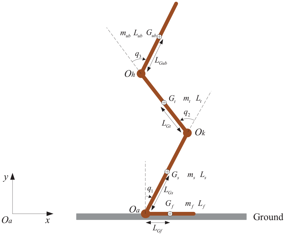
Model of the load-carrying exoskeleton in the stance phase.
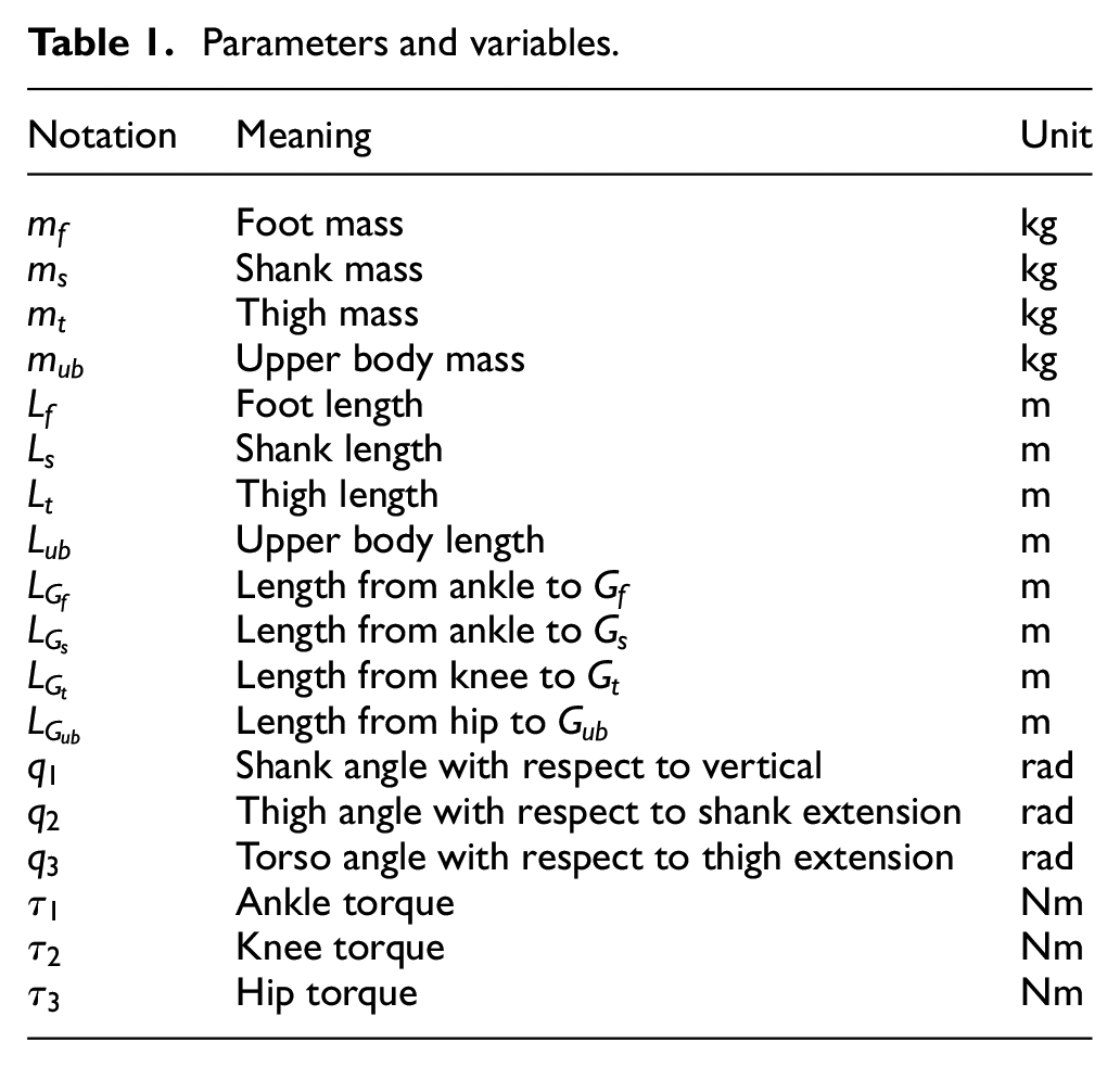
Parameters and variables.
As mentioned above, load-carrying exoskeleton saves wearer’s efforts by transferring heavy loads to the ground. The transfer progress only occurs in the stance phase. Thus, we mainly consider device activities in the stance phase of the sagittal plane. Figure 1 shows a state of two feet stand. A squat movement, which is a typical activity of the stance phase, is applied and researched in the following work.
The dynamic model of the stance phase exoskeleton is designed with Eural–Lagrange equation and is expressed as

where
Note that the payload, which is usually mounted on the back of the exoskeleton torso, is not modeled considering its variation. That is, equation (1) is a non-loaded model and the existence of load will definitely influence the accuracy of

If the exoskeleton tracks the reference trajectory decided by the wearer well, then the interaction force will be minimum, and that is what a load-carrying exoskeleton should achieve.
Method
The whole control structure is shown in Figure 2. The inputs of the exoskeleton include three parts: the physical human–robot interaction (pHRI) force
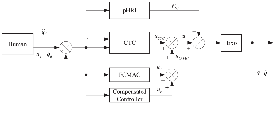
Block diagram of the proposed control scheme.
CTC controller
The control law is designed as the following form


where
Substituting equations (3) and (4) into equation (1), the system dynamic equation is updated as
where

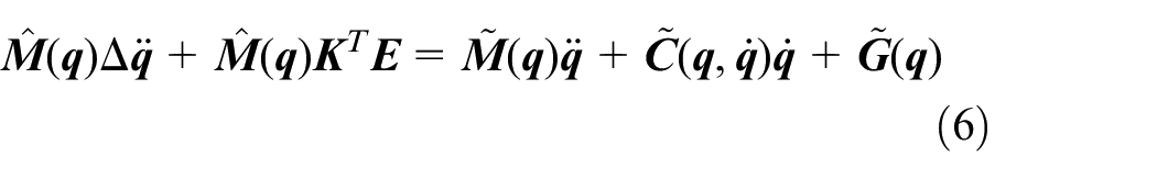
Take equations (5) and (7) into equation (6), we get

The system will be stable as long as the coefficient matrices
Architecture of FCMAC
FCMAC architecture is similar to the conventional CMAC. The difference is that FCMAC uses Gaussian basis function as receptive field basis function rather than local constant binary function. Figure 3 shows the architecture of an

The function
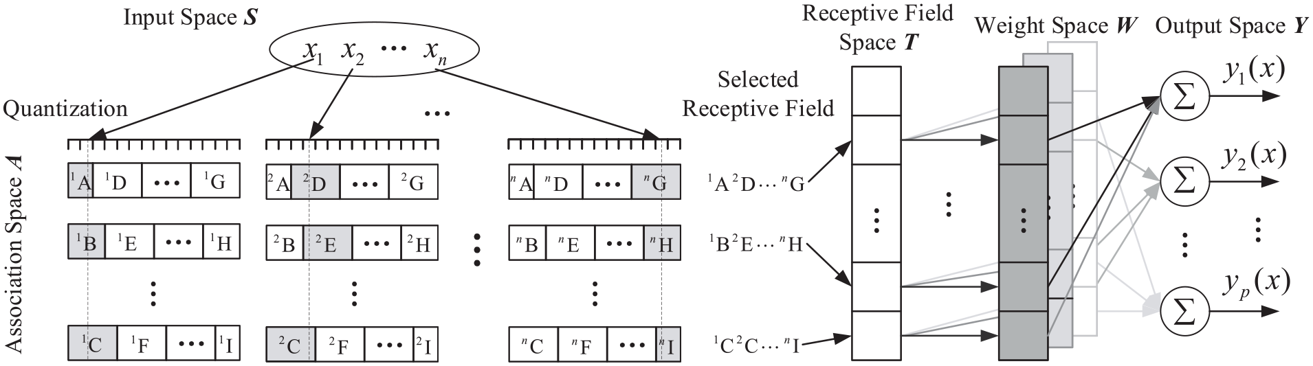
Architecture of CMAC.
Quantization
Each data of the input vector
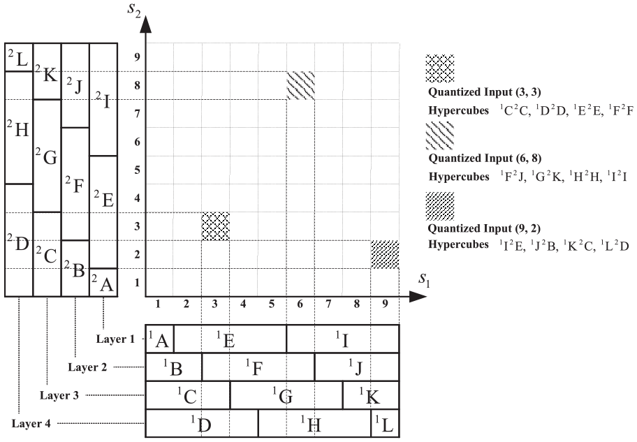
Quantization and mapping of CMAC with two inputs.
Receptive field function
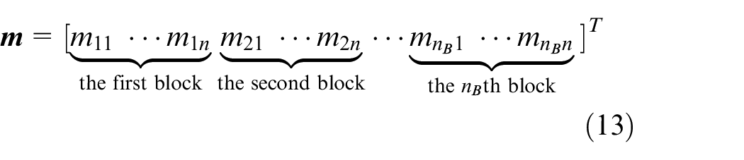
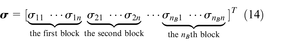
After quantization, each input is mapped onto the association space and be represented by multilayer blocks. The association space of each input is constructed with
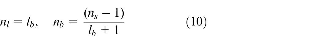
Thus, any input data can be mapped to
Each block corresponds with a receptive field basis function. The basis function is effected only in its related block. Any continuously bounded function can be used as the basis function, and the Gaussian function is used in this work. The basis function of the kth block of the jth layer of the ith input
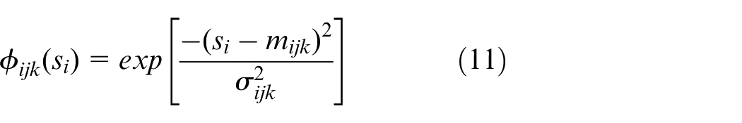
Note that
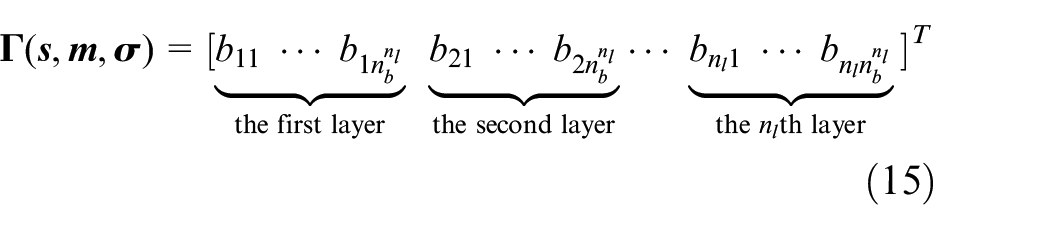
Any input point

where
Define
There are
All networks have the problem of dimensional explosion, and CMAC is no exception. As mentioned above, a CMAC with
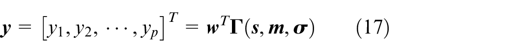
Weight space and output
Each hypercube corresponds to a specific weight when mapping to a specific output. Suppose the output dimension is
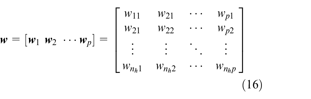
in which
For example, if two input vectors are quantized to (2.1, 2.4) and (2.5, 2.6), respectively, they are both located at the square (3,3) and represented by the hypercubes 1C2C, 1D2D, 1E2E, and 1F2F.
FCMAC and compensated controller
Redesign the control law equation (3) as

Then equation (6) can be rewritten as

in which

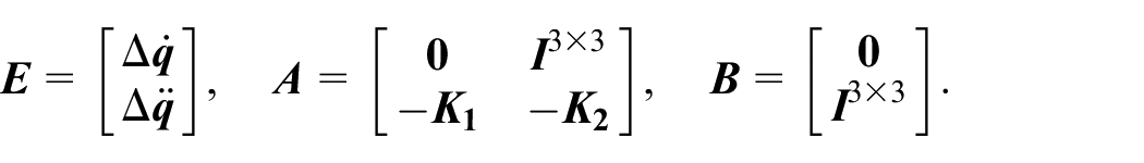
The system state-space dynamic model can be written as

where
If there exists ideal weight values
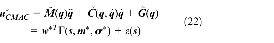
in which

To minimize the approximation error of the network, a compensation quantity

where
where
The optimal hypercube function set is represented as

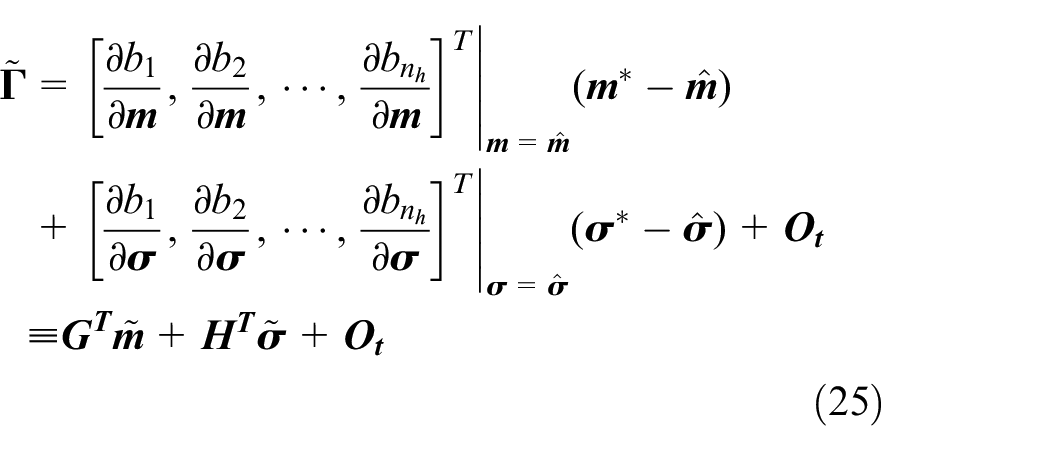
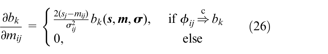
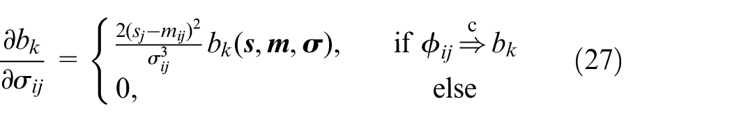
Substitute equations (20), (22), (24), and (28) to equation (21)
in which


where

and
As for the load-carrying exoskeleton described in equation (1), the control laws, which correspond with the control scheme in Figure 2, are entirely designed as

in which
Stability analysis
Define the Lyapunov function as
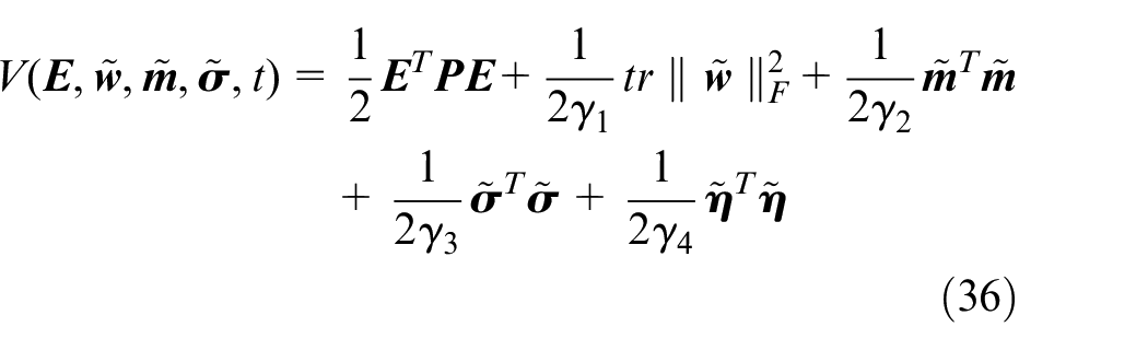
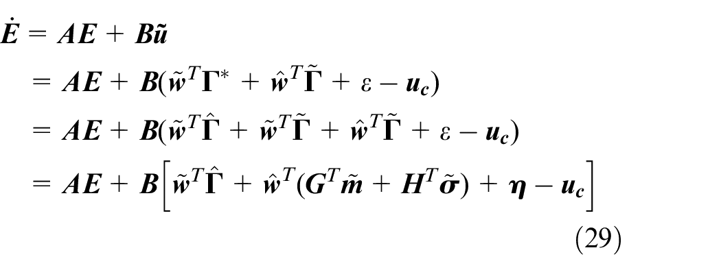
Taking the derivative of the Lyapunov function and substituting equations (29) and (34) successively, we get
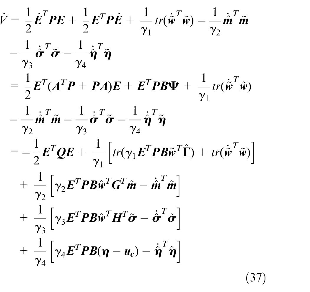
According to equations (30)–(33), equation (37) is simplified as
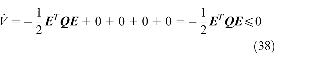
where
Simulation
The proposed method is verified through simulations. The leg on the stance phase rather than the swing phase is selected as the application object because the load variation has a slight influence on the swing leg. A squat movement is used in the simulation. The desired trajectories of the ankle, knee, and hip joints are obtained through the fitting results of human squatting data, which are collected by the motion analysis equipment. Figure 5 is the squatting progress during the simulation.
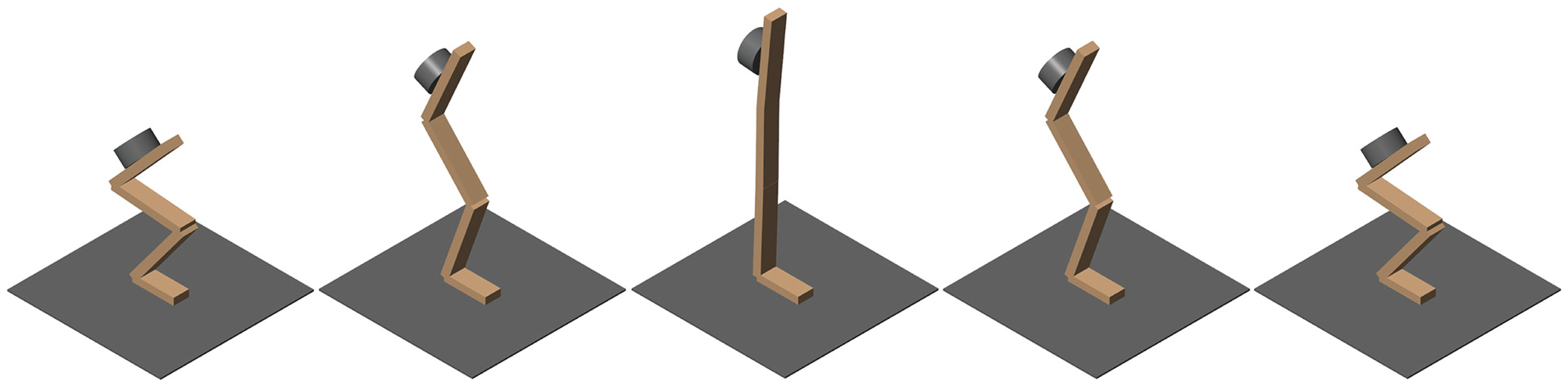
Exoskeleton squat progress simulation. The payload is fixed on the back.
The average mass
As for FCMAC network, joint angle displacements and their differential
Three groups of simulation in different conditions are designed in this paper. The first is without model uncertainties. The second is with model parameter changes, and the last is with load changes.
Simulation without uncertainties
In this condition, no load is added on the exoskeleton. The dynamic system model is definite and is used in the CTC controller design. The parameters used in the controller are designed as
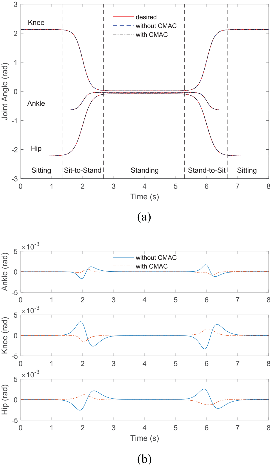
Squatting control without uncertainties. (a) Trajectory tracking. (b) Tracking errors.
Simulation with model parameter changes
The model parameter changes come from the modeling simplification and the measuring errors. In this condition, the load is not considered for the moment. For simplicity, we set the model parameter changing by adjusting the value of
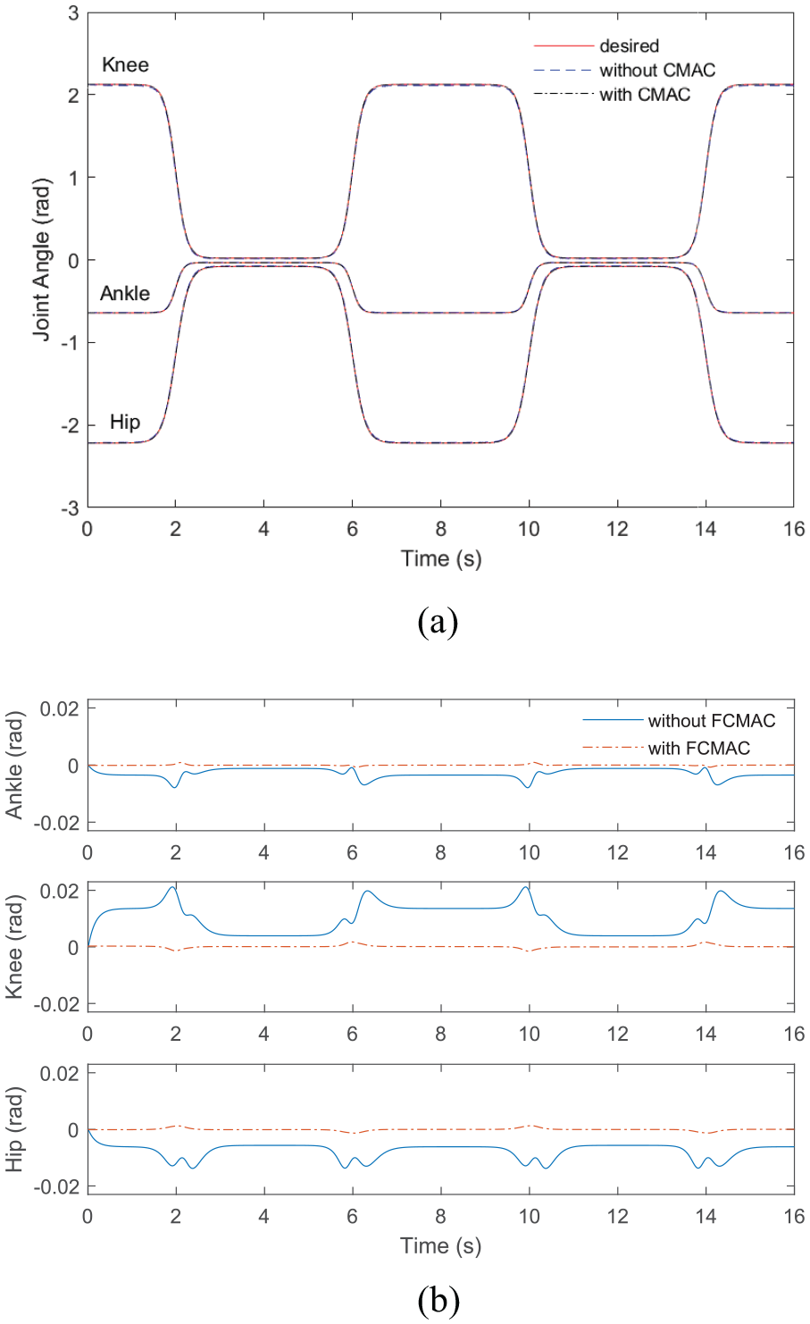
Squatting control with model parameters increase 40%. (a) trajectory tracking and (b) trajectory errors.
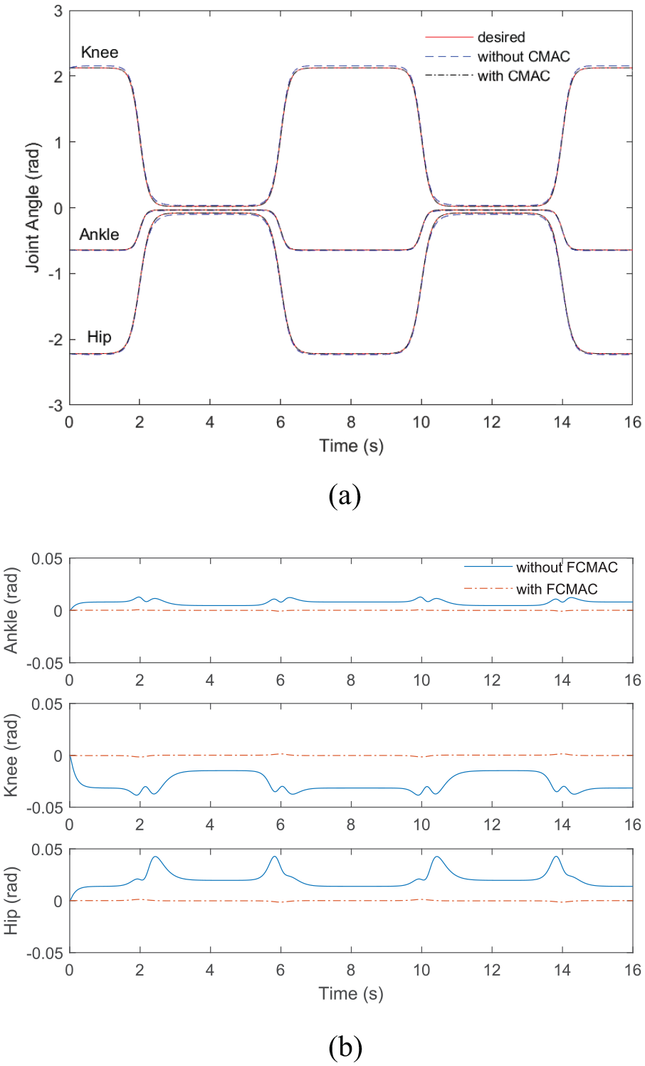
Squatting control with model parameters decrease 40%. (a) Trajectory tracking. (b) Trajectory errors.
In the condition that the model parameters increase 40%, the maximum tracking errors of the control without FCMAC and with FCMAC are
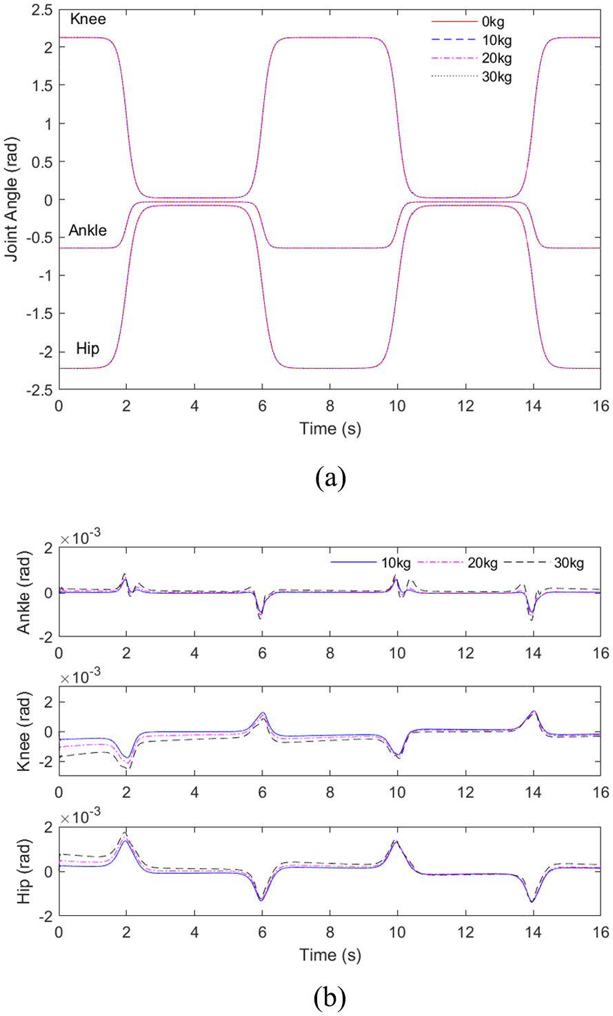
Simulation with load changes
The load adheres to the exoskeleton torso. During the working, the load supported by the exoskeleton can be changed frequently; for example, loading and unloading equipment, weapon launching, fuel consumption, and so on. Thus the control system should have the ability to cope with load variations. In this condition, only load mass variation is considered, and the load position and orientation variations are not taken into account, which can be regarded as the model parameter changes in the above subsection.
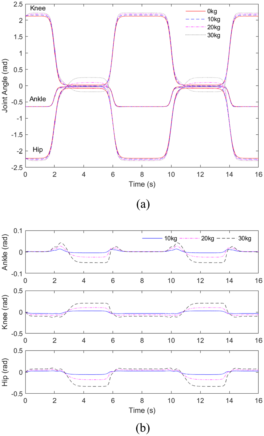
The initial state of the system used in the simulation is non-loaded. Three groups of simulation are designed with 10, 20, and 30 kg load, respectively. The controllers stay the same as subsection “Simulation without Uncertainties.” The tracking responses are illustrated in Figure 9. For comparison, the tracking responses without FCMAC controller are displayed in Figure 10.
Squatting control of load changes with FCMAC. (a) Trajectory tracking. (b) Trajectory errors.
Squatting control of load changes without FCMAC. (a) Trajectory tracking. (b) Trajectory errors.
Along with the adding of load, the tracking error of both the controls with FCMAC and without FCMAC is increasing. However, the control without FCMAC is hard to track the desired trajectory, especially when the load is heavy. The maximum tracking errors of the three joints under the condition of 30 kg load in Figure 10 are 0.05, 0.21 and −0.33 rad, respectively. While using the control with FCMAC, the maximum tracking errors are reduced to
Conclusion
A trajectory tracking controller associated with FCMAC compensation for load-carrying exoskeleton in the stance phase is proposed in this paper. The control scheme is mainly composed of CTC and FCMAC. The CTC is the primary controller for the trajectory tracking and has a benefit of smooth control quantity compared with the sliding mode controller. The FCMAC is used to approximate the dynamic model uncertainties. The system stability is proved by the Lyapunov function. The simulation results show that the proposed control strategy has a perfect tracking response in squatting movements and can better deal with situations, such as model uncertainties and load variations.
The proposed controller has a robust ability of system uncertainties. As to the flexibility of the load-carrying exoskeleton, it can be affected by many factors besides the robust control. First, the flexibility is related with the load weight and the motion state. In practical applications, the power of the actuators of the exoskeleton is limited. Second, the load-carrying exoskeleton can be regarded as a biped robot. During walking, the flexibility of the exoskeleton is mainly affected by the swing phase and the swing–stance–switch phase. Then, if the system uncertainties are too large, the proposed control method cannot guarantee the tracking effect. Because the higher-order term
Future work includes designing proper association space of FCMAC, researching non-linear quantization of FCMAC, and simulating the control strategy on various movements. Considering that the proposed control strategy has a high tolerance of uncertainties, the swing leg of the exoskeleton can be regarded as disturbances of the stance phase model, thus the control strategy of the complex activities can be simplified. The method will be evaluated on a physical system in the future.
Footnotes
Declaration of conflicting interests
The author(s) declared no potential conflicts of interest with respect to the research, authorship, and/or publication of this article.
Funding
The author(s) disclosed receipt of the following financial support for the research, authorship, and/or publication of this article: This research was funded by the National Key R&D Program of China, Grant No. 2018YFC2001304.