
Abstract
For the rapid response of the aircraft, it is required that the aircraft is not only quick but also chooses the shortest flight routes. The great circle track is the shortest flight route on the earth between any two points, but the great circle track needs to cross the polar region when the aircraft flies over the hemispheres of East and West. Because the polar region has some particularity, such as the landform characteristics, the climatic conditions, and the vast territory, the transpolar aircraft is the key technology of global navigation. This article researched on the algorithm of SINS/GPS integrated navigation system and analyzed the result of simulation when the SINS/GPS integrated navigation system works in the middle- and low-latitude region and the polar region. The result of simulation shows that the working performance of SINS/GPS integrated navigation system is improved and makes use of their respective advantages to overcome the shortcomings. By comparing the result of simulation, the navigation precision is consistent when the SINS/GPS integrated navigation system works in the middle- and low-latitude region and the polar region.
Keywords
Introduction
Because of the special geographical position of the polar region, the inertial navigation system (INS) can only calculate the matrix of position and attitude, but cannot obtain the position and attitude. The main reason is the longitudinal convergence of a point in the polar regions. To avoid the matter which is difficult to location, it is abandon the traditional definition of latitude and longitude, which the longitude is convergence to a point in the polar regions.1,2
SINS/GPS algorithm which located the middle and lower latitudes
First, the flight parameters are measured using strapdown inertial navigation system (SINS) and global satellite navigation system (GPS). Second, the observed quantity of the SINS/GPS is the difference of flight parameters between SINS and GPS; the SINS also adopts the Kalman filter for information fusion and correcting the errors. Finally, the calibration parameters of the SINS are used as the output of the SINS/GPS integrated navigation system. 3 The scheme of the SINS/GPS integrated navigation system is shown in Figure 1.

Scheme of the SINS/GPS integrated navigation system.
State equation of SINS/GPS which located the middle and lower latitudes
Based on the error state equation of SINS, the state variables of SINS/GPS are selected as follows:

The state equation of SINS/GPS can be written as

where
Measurement equation of SINS/GPS which located the middle and lower latitudes
The observed quantity is the difference of flight parameters which are velocity and position between SINS and GPS, so the measurement of SINS/GPS is
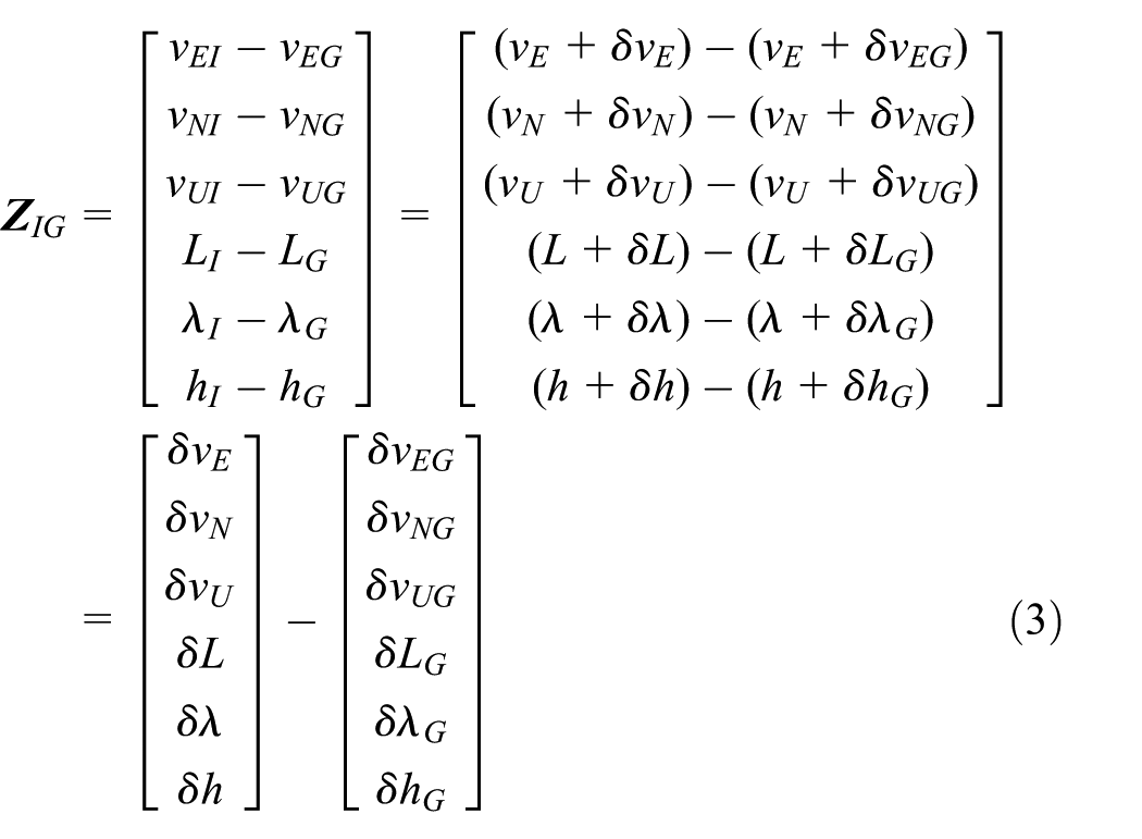
where
Combined with the system state vector of SINS/GPS, the measurement equation of SINS/GPS is presented as

where
Simulation of SINS/GPS which located the middle and lower latitudes
The parameters of gyroscope and accelerometer are as follows: the constant drift of gyroscope is
The parameters of GPS are as follows: the velocity error of GPS is
The initial navigation errors are as follows: the attitude error is
The results of simulation are shown in Figure 2.
(a) Estimate error of attitude, (b) estimate error of velocity, (c) estimate error of position, (d) constant drift of gyroscope, and (e) constant offset error of accelerometer.
According to Figure 2(a)–(c), the navigation parameter error of SINS is convergence. After 1800 s of simulation, the azimuth error is stable at 10′, the pitch error is stable at 0.5′, the roll angle error is stable at 1′, the velocity error in three directions is not more than 0.1 m/s, the latitude error is not more than 6 m, and the longitude error is not more than 5 m. Thus, it can be seen that the SINS/GPS makes full use of the measurement information of GPS, and the navigation precision of the system is improved because the integrated navigation effectively overcomes the defect of SINS.
According to Figure 2(d), the constant drift of gyroscope is estimated by SINS/GPS. It is better that in the gyroscope of x-axis and y-axis, the estimation results are very close to the real value of gyroscope (0.01°/h). However, the estimation result of z-axis is very poor. The constant drift of gyroscope is not estimated in 1500 s of simulation. The main reason is the poor observability of the integrated navigation system on the z-axis.
According to Figure 2(e), the constant offset error of accelerometer is estimated by SINS/GPS. It is better that accelerometer of x-axis and z-axis, but the estimated convergence time is too longer, x-axis is estimated until 1000 s and z-axis is estimated until 400 s. The estimated results are very close to the real value of accelerometer 40 µg.
Grid reference frame
The basic idea of grid reference frame is that the longitude is parallel to the Greenwich meridian in the polar chart, and the azimuth measurement of aircraft will be relative to the Greenwich meridian, which can avoid the longitudinal convergence of the point and solve the problem of orientation in polar regions.6,7
Definition of grid reference frame
It is supposed that P is the position of aircraft; grid plane is parallel to the Greenwich meridian; the horizontal plane of the aircraft is the tangent plane; the grid north is the intersecting line between the grid plane and the tangent plane;

Grid reference frame.
Mechanic equations of grid navigation system
There are many similarities between the grid navigation system and the wander azimuth INS; however, there are differences in the instruction of angular velocity.
Attitude angle differential equation
The grid navigation system is the navigation coordinate system, and the attitude angle differential equation is shown as

where the initial

The grid reference frame is a horizontal coordinate. Therefore, there is a relationship between the horizontal component of

From the relationship between the grid reference frame and the geographic coordinate system, we can obtain
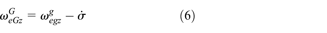
where


so

and

Velocity differential equation
The mechanic equation based on the grid navigation coordinates is as follows

and

Position differential equation
The positioning information of north azimuth inertial navigation is attained by numerical integration of the position direction cosine matrix. In the polar region, the position information of aircraft is indicated by the earth-centered earth-fixed (ECEF) coordinates10,11

When
Algorithm of SINS/GPS integrated navigation in the polar region
The north azimuth of INS is used in the middle- and low-latitude regions; the heading reference of SINS and the GPS system is the true north. The grid reference frame of INS is used in the polar region to overcome the problem of directional convergence of longitude, and the heading reference of the GPS system is the grid north.12,13
State equation of SINS/GPS integrated navigation in the polar region
Similar to the middle and low latitudes, the state variables of SINS/GPS are as follows: the attitude error of SINS is

Based on the error state equation of SINS and the system state vector of SINS/GPS, the state equation of SINS/GPS can be written as

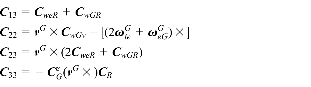
where
It is expanded from equation (9)

where
Measurement equation of SINS/GPS integrated navigation in the polar region
In the polar region, the position of GPS and SINS is based on the ECEF. The observed quantity of the SINS/GPS integrated navigation is the difference of flight parameters between SINS and GPS, so the velocity of SINS is converted to the ECEF
The measurement of SINS/GPS

Combined with the system state vector of SINS/GPS, the measurement equation of SINS/GPS is presented as

where
Simulation of SINS/GPS integrated navigation in the polar region
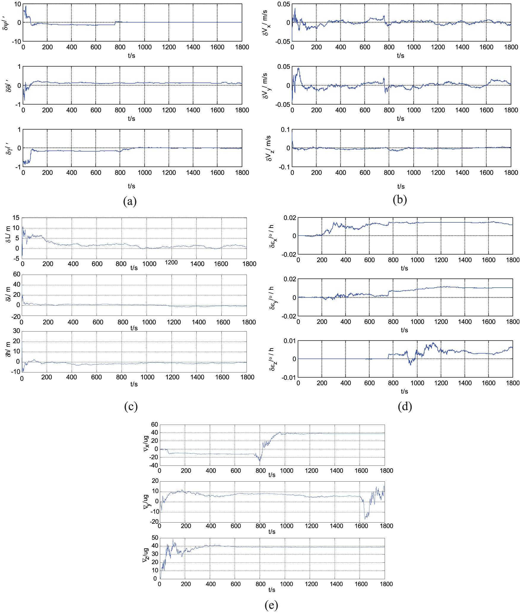
In the polar region, the simulation parameters of SINS/GPS integrated navigation are the same as the middle and low latitudes. The results of simulation are shown in Figure 4.
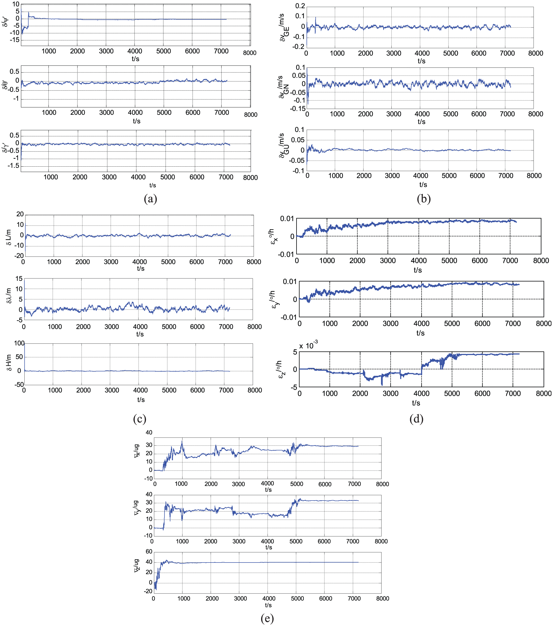
(a) Estimation of attitude error, (b) estimation of velocity error, (c) estimation of position error, (d) random constant drifts of gyroscope, and (e) random error of accelerometer.
According to Figure 4, after 7200 s of simulation, the azimuth error is stable at 5′; the pitch error and the roll angle error are stable at 0.5′; the velocity error in three directions is not more than 0.1 m/s; and the latitude error and the longitude error are not more than 5 m. But the constant drift of gyroscope and the constant offset errors of accelerometer are not estimated until the turn maneuver; the estimation of gyroscope is 0.01°/h, and the estimation of accelerometer is 40 µg.
Analysis of simulation result
Whether in the middle and low latitudes or in the polar regions, the error of attitude, the error of velocity, and the error of position are the difference between the adjustment and the real, the constant drift of gyroscope, and the constant offset errors of accelerometer, which are estimated by the Kalman filter.
The results of simulation show that the navigation precision is consistent when the SINS/GPS integrated navigation system works in the middle- and low-latitude region and the polar region. The SINS/GPS integrated navigation system, which is based on the grid inertial navigation, could improve the precision of transpolar navigation and guarantee the security and reliability of aircraft.
Footnotes
Academic Editor: Chenguang Yang
Declaration of conflicting interests
The author(s) declared no potential conflicts of interest with respect to the research, authorship, and/or publication of this article.
Funding
The author(s) disclosed receipt of the following financial support for the research, authorship, and/or publication of this article: This work was partially supported by the Special Scientific Research Project of the Education, Department of Shaanxi Provincial Government, School Foundation Research Fund, and the National Natural Science Foundation of China (project nos 15JK14, 14JK1429, JC1702, and 51678470).