
Abstract
Global navigation satellite system signals are easily distorted by the interferences or disturbances, and global navigation satellite system receivers cannot offer continuous effective navigation results in challenging environments. As a representative regional augmentation technology, pseudolite has the potential to provide accurate positioning service to satisfy specific performance requirements in various applications. In this article, we developed a dynamic localization network based on pseudolite technology for regional augmentation navigation purpose. First, the collaborative positioning algorithm is given, and the architecture of localization system is proposed. Then the error sources of localization system are analyzed for performance evaluation. Finally, the proposed system is verified by experiments conducted in both static and kinenatic scenarios. The experiment results demonstrate that the positioning accuracy of the proposed localization system is nearly 10 m, which is close to the global navigation satellite system single-point positioning accuracy. Therefore, it can be used for emergency dynamic positioning of critical areas under the global navigation satellite system denial environments.
Keywords
Introduction
As a typical navigation system, the global navigation satellite system (GNSS) has become a ubiquitous source of positioning, navigation, and timing services and has been evolved into modernized multi-application, multi-system, and multi-purpose national infrastructure. 1 However, GNSS signals are vulnerable and easily distorted by interference, occlusion, and so on, which limit the positioning availability for civilian applications, such as in the area of mountains, canyons, cities, and indoor environments. For military use, such as aircraft control, unmanned aerial vehicles (UAVs) formation flying, and collaborative combat, GNSS is also required to provide high-accuracy positioning in challenging environment.2,3 Therefore, navigation augmentation technology is a necessary solution to obtain precise positioning navigation and timing information in GNSS rejection environments.4,5
Regional augmentation navigation technologies mainly include satellite-based augmentation systems (SBASs) and ground-based augmentation systems (GBASs). 6 SBAS refers to signal-enhanced transponders carried by geostationary earth orbit (GEO) satellites or low earth orbit (LEO) satellites, which can broadcast various correction information such as ephemeris error, satellite clock error, and ionospheric delay to users to achieve improved positioning accuracy of the existing GNSS. The established GEO-based SBAS systems worldwide include the US wide area augmentation system (WAAS), the European geostationary navigation overlay service (EGNOS), the Japan multi-functional satellite augmentation system (MSAS), and the Indian global positioning system (GPS)-aided geo augmented navigation (GAGAN). Recently, LEO-based SBAS has also driven much attention, and various missions have been launched, 7 such as Oneweb, Starlink, and China’s Hongyan satellite constellation communication system. GBAS is developed on the basis of differential technique to improve positioning accuracy. The latest progress in GBAS area is integrity-monitoring algorithms which aim to improve the integrity, availability, and continuity of the navigation system, so that higher and more reliable position information can be obtained in the coverage area. 8 However, both SBAS and GBAS need to be built at the national level with high cost and in combination with GNSS, resulting in limitations on their applications.
With the development of pseudolite (or pseudo-satellite, abbreviated as PL) technology, the positioning systems based on PL have been widely applied in indoor, underground, flight navigation, and so on. The cooperative localization using PL and GNSS has also become one of the effective ways of improving GNSS positioning accuracy.9,10 The PL refers to a transmitter deployed on the ground to transmit a certain positioning signal, usually some GNSS like signals. PL improves not only satellite geometry dilution of precision (DOP) but also availability, reliability, and precision of the system.
However, PL positioning technology still has many issues to be addressed, such as multipath and near–far effects and time synchronization. Liu et al. 11 designed PL signals to overcome near–far effect, but the receiver needs to be completely revolutionized, and the complexity makes it difficult to be popularized and realized. For multipath suppression, multipath estimation delay lock loop (MEDLL) proposed by Novatel company has been widely used for anti-multipath receivers.12,13 Time synchronization of pulsed PL system has been initially studied by Wang et al., 14 and then Daniele et al. 15 used a modified receiver signal strength (RSS) algorithm to enhance the signal C/N0 to achieve accurate timing and positioning of asynchronous pseudo-satellite. Furthermore, Gioia and Borio16,17 discussed the strategy of stand-alone and hybrid positioning based on the asynchronous pseudolites.
At present, Locata system, that is developed by Australia’s Locata, is one of the successfully operated ground-based “non-GPS positioning systems.” The Locata system utilizes a small ground-based pseudolite transmitter network to transmit strong radiolocation signals for positioning and navigation in the covered area. However, the multipath and near–far effects in the Locata system have not been well addressed. Jiang et al.18,19 developed a GNSS/INS-based Locata system architecture and proposed a multi-system data fusion localization algorithm to improve positioning performance. However, as the Locata system transmits strong radio signals, it may cause interference to the surrounding environment, and the system also has low flexibility and high cost.
In this article, the research on the PL-based dynamic regional localization system in the GNSS denial environment is conducted. First, a collaborative positioning algorithm of PL and GNSS is analyzed. Then, a PL positioning system architecture is designed. In order to solve the time synchronization problem among different pseudolites, a master–slave PL communication link is proposed. Finally, the performance of the proposed localization systems is investigated.
This article is organized as follows: in section “Collaborative positioning algorithm,” the principle of positioning is described, and the cooperative localization algorithm is introduced. The dynamic localization system is discussed in section “Dynamic localization system design.” Error analysis and synchronization strategies are studied in section “Error analysis and synchronization strategy.” Experimental results are described in section “Experimental results and analysis,” and finally, conclusions are made in section “Conclusion.”
Collaborative positioning algorithm
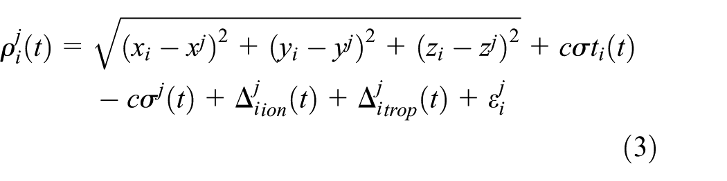
According to Wang and Lian, 20 the pseudo-range observation of GNSS system is commonly expressed as

where

where
Four unknown variables existed in equation (3):
In the collaborative positioning system with PL, the PL pseudo-range observation is similar to that of GNSS in equation (1). It is ionospheric and tropospheric free, but instead multipath errors need to be considered. As expected, the PL pseudo-range observation can be expressed as

where subscript i represents receiver index, and
When using GNSS satellites and PL for collaborative positioning calculation, the positioning equation can be expressed as

where
Equation (5) can be solved by the following steps:
Step 1. Set the initial solution to give an initial estimate of the receiver position coordinates
Step 2. Linearize the nonlinear equation (5). In the k iterations of the current moment, equation (5) can be linearized at
Finding partial derivatives for equation (2)


From this, we can get equation (8) after linearization at

where G and b can be expressed as


where
Step 3. Solve the equation (8) whose least squares solution is

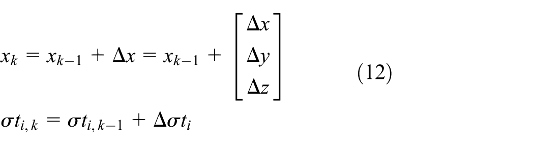
Step 4. Update the solution of the original equations to further obtain the coordinates and clock difference of the receiver
Dynamic localization system design
Architecture of localization system
A typical regional positioning system usually consists four pseudolites, one of which is set as the master pseudolite (MP), and the other three are set as the slave pseudolite (SP). The main difference between the MP and SP is that the MP has a GNSS receiver, which is used to generate a reference signal synchronized with the GNSS time, while the SP has a time reference reception channel. But both of them have their own spread spectrum signal transmission channels for positioning. The structure of the localization system is shown in Figure 1.

An example of pseudolite localization system.
In the system, the MP receives the GNSS satellite signals to obtain the GNSS time reference and then uses the time reference signal to synchronize the MP clock. The MP will send a timing signal to the SPs by wireless transmission. The SPs receives the timing signal and calculates the propagation time, which is then used to synchronize the SPs with the MP and GNSS systems. The precise positions of MP and SPs will be pre-calibrated so that their ephemeris can be produced according to the time and position information, respectively. Then the ephemeris will be broadcasted by pseudo-noise code and received by users. When there are more than four visible PLs or GNSS signals, pseudo-range equations can be solved, and the collaborative positioning algorithm can be used to calculate the user’s positions. The PL localization system composition is shown in Figure 2.

Components of PL localization system.
MP
The MP reference generator is driven by a high-stability, temperature-constant crystal oscillator (frequency stability is less

Processing flow chart of MP.
As shown in Figure 3, the MP includes the following modules:
Antenna module: MP contains three antennas, the first one is the GNSS antenna for receiving GNSS signals, the second one is the time reference signal transmitting antenna for sending time reference signal to SP, and the third one is used to send PL positioning signal to user receiver.
Time synchronization module: according to the time signal generated by the GNSS receiver and a high-stability oscillator of MP, this module generates a pseudolite time reference, and then, by which two signals can be generated as well. One of the signals is the synchronous signal transmitted to SP and the other one is the positioning signal transmitted to user.
Baseband signal generation module, where the baseband positioning signal with spread spectrum modulation is generated.
Power amplifier module: MP has two power amplifiers for amplifying the time synchronous signal and the positioning signal, respectively.
SP
SP receives the synchronization signal from the MP and the clock information will be extracted through low-noise amplifier (LNA), mixer, intermediate-frequency (IF) amplifier, and demodulator. Then after frequency synthesis, the clock information will be transmitted to the user via baseband signal generation module and the power amplifier. The signal processing flow chart is shown in Figure 4.

Processing flow chart of SP.
As shown in Figure 4, the SP comprises the following modules:
Antenna module: two antennas are being used in the SP, where one is for receiving the time reference signal from the MP with center frequency at 938.4 MHz. The other one is a positioning signal transmitting antenna with center frequency at 2537.6 MHz. Both antennas are horizontally polarized and have a 6 dB gain.
LNA module.
Frequency synthesizer module.
Baseband signal generation module.
Power amplifier module.
Error analysis and synchronization strategy
Positioning error analysis
In practical applications, the positioning errors mainly come from the following sources:
Satellite errors, such as ephemeris error, satellite clock error, and satellite equipment delay error.
Receiver errors, such as measurement errors, calculation errors, and device delay errors.
External environmental errors during signal propagation, such as tropospheric propagation delay, ionospheric propagation delay, and multipath effects.
Near–far effect errors: the near–far effect is that the power density of electromagnetic waves emitted by pseudolites is inversely proportional to the square of the distance. Therefore, the inequal signal powers received by users from the near and far PLs will affect positioning performances.
The first three error sources are existing in both GNSS and pseudolite, but the fourth one is unique to the pseudolite system.
When the user is moving toward pseudolite, the received pseudolite signals get stronger and stronger. GNSS signal will be much weaker than that of the nearby pseudolite, and the pseudolite signals will overwhelm the GNSS signals. Contrarily, when the user is moving away from pseudolite, the pseudolite signals will be buried in the relatively strong GNSS signals. An illustration of near–far zone division is shown in Figure 5. The receivers operating with dual-system simultaneously, that is, GNSS and pseudolite, are quite sensitive to the near–far effects. This will be a challenging issue in regional navigation system design.

Diagram of near–far effect.
In this article, we assume that the farthest and closest distances between the user and the pseudolites are 10 km and 100 m, respectively, to make sure there is a maximum 40 dB power difference in near–far pseudolite signals. Therefore, the near–far problem in the pseudolite positioning system can be addressed by increasing receiver dynamic range via analog-to-digital converter (ADC) in the receiver front-end. Usually, the dynamic range of an N-bit ADC in a navigation receiver is 20lg(2 N ). The current GNSS receiver usually takes 4 bit or 8 bit ADC design with a maximum 48 dB dynamic range. However, in this article, we use a 16-bit ADC to increase our dynamic range to 96.32 dB level to suppress the near–far effect.
Synchronization strategy
In the localization system, the time synchronization performance among different pseudolites directly affect positioning accuracy. To achieve the accurate time synchronization, a wireless channel is established between the MP and the three SPs. The MP generates a synchronization code with system time reference information and transmits to the SPs through the wireless channel. The SPs receives the synchronization code and restores the clock information to guarantee synchronization between the SPs’ and the MP’s clocks.
The synchronization code is directly generated by the time base of the MP, and then the code is modulated onto the carrier for transmission. At the SPs, the antenna receives the signal transmitted by the MP, and demodulates the synchronization code by synchronous code recovery circuit. The clock recovery is the most critical part of the synchronous design. A phase-locked loop is used in this design to recover the system clock. The recovery flow of the system clock is shown in Figure 6.

Composition of the clock recovery.
In addition, a high-performance temperature-constant crystal oscillator is used in the design of the time base of the base station to ensure the time accuracy. The temperature-constant crystal oscillator has high-frequency stability, low-phase noise, and low aging rate, which ensures the accuracy, stability, and reliability of the time base in the entire system.
Experimental results and analysis
Time synchronization set up
In our experiments, the time synchronization between MP and SPs is first set up. The MP clock is driven by temperature-constant crystal oscillator, and the SPs’ clocks are synchronized by demodulation and recovery of the received MP pseudo code signal. The MP and SPs clock spectrum are shown in Figure 7. It can be found that the recovered synchronous SPs clock has a very-low-phase noise and is completely synchronized with the MP clock.
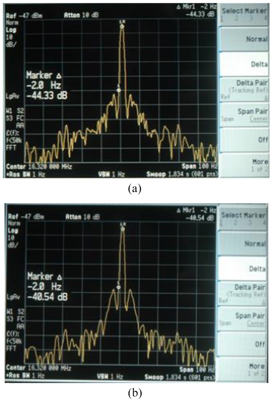
Clock spectrum of (a) MPs and (b) SPs.
Short-distance static test
In the short-distance static experiment, we chose four unshielded points to place pseudolites on the Chang’an Campus of Northwestern Polytechnical University. The pseudolites position coordinates and layouts are shown in Table 1 and Figure 8, respectively.
PL coordinates for static experiment.
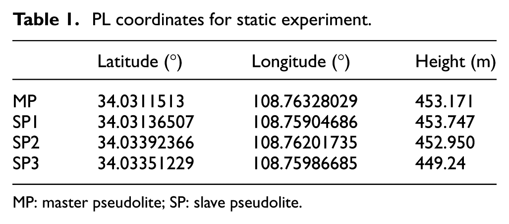
MP: master pseudolite; SP: slave pseudolite.

Pseudolites distribution for short-distance test.
Positioning error calculation
Taking GNSS results as the benchmark, the positioning results of using PL system are compared with those of using GNSS. The PL-positioning errors relative to GNSS reference coordinates are measured. The following error performance indexes are calculated:
Error mean: the PL measured value of latitude and longitude is subtracted from the GNSS reference coordinates to obtain the average error and the coordinate errors are finally converted to distance unit. The transformation formulas are as follows:
Distance error in latitude direction = latitude error * 110880
Distance error in longitude direction = longitude error * 110880 * cos (mean of latitude).
Error variance of error: the error variance between the PL measured value and the GNSS reference coordinate are calculated first and then being convert to distance unit. The conversion method is consistent with the above.
Circular error probable (CEP): CEP is a parameter of evaluating measurement accuracy due to systematic bias. CEP is defined as the circle radius that contains a certain probability (i.e., the circular probability index, CPI = 50%) of measurement value relative to its average center.
Experiment results
In the static experiment, we select a non-obstructed test point and use the differential GNSS receiver to accurately measure the coordinates of the test point. the coordinates of the test point obtained by GNSS receiver is
Latitude: 34° 02′ 026″N
Longitude: 108° 45′ 707″E
The pseudolite receiver is used to receive the positioning signals transmitted by the four PLs. Experiment duration is about 10-min long. We use equations (7)–(12) in section “Collaborative positioning algorithm” to solve the pseudo-range equations and obtain the positioning coordinates. The PL-positioning results are shown in Figure 9. It can be observed that the PL-positioning results are consistent to GNSS coordinates, indicating the effectiveness of the proposed PL navigation system design.

Measured error of static test point: (a) longitude direction and (b) latitude direction.
The error mean, variance, and CEP of the error distribution can be calculated from the measurements showed in Figure 9, see Table 2. Note that the reference point in the CEP calculation is selected as the averaged measurement distance, and the error mean and variance are selected from GNSS measurements.
Short-distance errors (unit: meter).

CEP: circular error probable; CPI: circular probability index.
Long-distance kinematic experiment
The long-distance experiment area is selected in the southern suburb of Xi’an, PLs are placed on both sides of the No.107 provincial road in the foot of the Qinling Mountains, and the receiver is placed on a vehicle driving along the highway at a regular speed. The coordinates of the four PLs are shown in Table 3, and the layout of experiment is shown in Figure 10.
PL coordinates for kinematic experiment.

MP: master pseudolite; SP: slave pseudolite.

The layout of the pseudolite around s107 provincial Road.
During the experiment, a fix point is selected for positioning-evaluation purpose. The coordinate of the fix point is accurately pre-calculated by the GNSS receiver under static scenes, as shown in subsection “Short-distance static test.” The driving speed is about 10–20 km/h, and 10-min movement trajectory is recorded by the GNSS receiver. The antenna of the pseudolite receiver is placed on the roof of the vehicle, as shown in Figure 11. The pseudolite signal is received by the PL receiver to verify the positioning performance of the localization system designed in this article. The fix-point positioning results in using PL under dynamic scenario are shown in Figure 12.
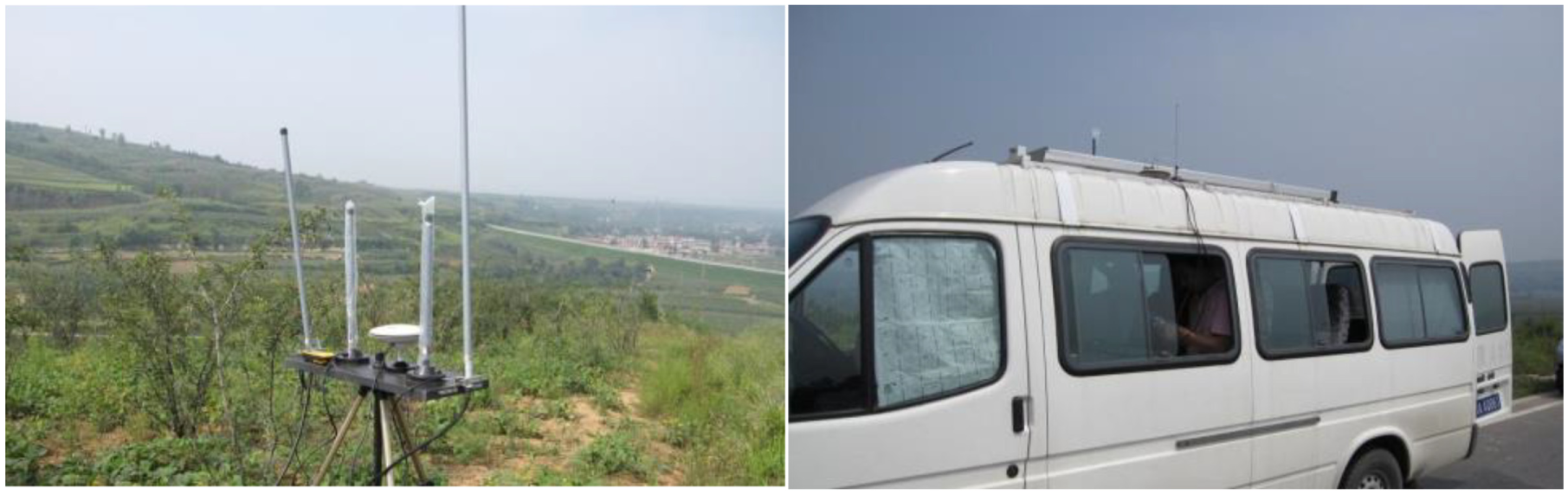
Experiment photos.

Dynamic PL positioning results: (a) longitude direction and (b) latitude direction.
Similarly, the error mean, variance of error, and CEP (CPI = 50%) of the fix-point position coordinates can be obtained from measurements in Figure 12. The error of static and kinematic results are shown in the Table 4.
Error of long-distance experiment.

CEP: circular error probable; CPI: circular probability index.
It can be seen from the Tables 2 and 4 that the pseudolite dynamic positioning system designed in this article can achieve the CEP accuracy of less than 6 m under the condition that the pseudolite is placed at a relatively close distance. When the pseudolite is placed far away, the positioning accuracy can also reach to nearly 14 m CEP level. The overall performance under the kinematic conditions is similar to that under the static conditions. The experimental results also indicated that the localization system designed in this article can provide the effective regional positioning services within 20 km2 coverage, which can satisfy the requirements of the emergency positioning under the GNSS denial environments.
Conclusion
This article proposed a dynamic localization network design based on pseudolites for regional navigation under GNSS denial environments. The performance of localization system was tested in static and kinematic conditions. The experiment results demonstrate that the positioning accuracy of the proposed system is nearly10 m, which can meet the emergency dynamic positioning of critical areas under the GNSS denial environments.
We will focus on the improvements of the pseudolites geometric DOP and location determination to further enhance the system performance, so that it can be applied to the fields of UAV cluster formation and distributed cooperative command in future.
Footnotes
Handling Editor: Daming Zhou
Author’s Note
The authors Hongwei Zhao and Xiaozhu Shi are now affiliated to State Key Laboratory of Air Traffic Management System and Technology, Nanjing, China.
Declaration of conflicting interests
The author(s) declared no potential conflicts of interest with respect to the research, authorship, and/or publication of this article.
Funding
The author(s) disclosed receipt of the following financial support for the research, authorship, and/or publication of this article: This work was supported by the National Natural Science Foundation of China (grant Nos.: 61771393 and 61571368), the Foundation of State Key Laboratory of Air Traffic Management System and Technology (grant No.: SKLATM201702), and the seed Foundation of Innovation and Creation for Graduate students in Northwestern Polytechnical University.