
Abstract
This article presents an approach to generate optimal couples of tool size and tool path for flank milling ruled surface with a conical cutter based on normal mapping, while at the same time keeping this couples within the given bounded constraints. For given initial pairs of taper tool and tool path, tool envelope surface is calculated. Then, the tool axis trajectory surface is related to envelope surface through the normal mapping. On this basis, the correspondence between the surface pair “design ruled surface–envelope surface–tool axis trajectory surface” is established, and it is used to obtain the signed flank milling error. By using this signed error, tool size and tool path optimization for flank milling is formulated as an optimization model subjected to bounds, and the trust-region-reflective least-squares method is used to solve this problem. Numerical example is given to confirm the validity of the proposed method.
Introduction
Flank milling is an operation to machine the workpiece with the side part of a cutter. This milling method is highly recommended for machining blades with ruled surface, because it allows access to areas that would be inaccessible to end milling. In addition, flank milling removes a considerable amount of material in one pass, and this leads to shorter machining times and greater productivity. However, when the non-developable ruled surface is flank-milled with cylindrical or conical tool, interference between the tool and the machined surface inevitably exists.1,2 This is the starting point of research on flank milling, and more methods are proposed to reduce this error. 3
First, the flank milling error is reduced from the perspective of tool path optimization, including local optimization and global optimization. Rubio et al. 4 developed an error distribution–based method for tool positioning, in which they make the tool axis parallel to the ruling line considered and position the cutter by letting errors equal on the two directrices of the surface. Bedi et al. 5 located the cutter by making it tangent to the two directrices at both ends of the rule surface. Then, the improved positioning method is presented in some papers,6–8 in which the tool is tangent with two directrices and in contact with the ruling involved at one point. Chiou 9 suggested adjusting the initial cutter location to reduce flank milling error by comparing the swept profile with the design surface. The above methods are local and discrete in nature since they focus on reducing error at one cutter location each time.
Compared to local optimization method, global tool path optimization no longer insists on optimal tool positioning at each single cutter location. Lartigue et al. 10 gave a new method to deform the tool axis trajectory surface, a ruled surface defined by two guiding curves, so that the tool envelope surface fitted the design surface as much as possible. Based on the conclusion that the envelope surface of cylindrical cutter is the offset surface of tool axis trajectory surface, Gong et al. 11 transformed the problem of reducing error between envelope surface of cylindrical tool and the designed surface into that of reducing deviation between the tool axis trajectory surface and the offset surface of the design surface, and a least-squares model is presented to obtain optimal tool axis trajectory surface. In a subsequent work, Gong and Wang 12 extended the idea to handle generic revolving tools, and formulated the optimization problem as that of least-squares fitting of tool axis trajectory surface to map surface. Zhu et al.13,14 proposed the signed point-to-surface distance function, whose first-order differential increment with respect to the differential deformation of the tool axis trajectory surface is analytical, and then Ding and Zhu 15 used the differential properties of the signed point-to-surface distance function to optimize tool path for five-axis flank milling with a cylindrical cutter. Subsequently, Zhu et al. 16 extended the work to deal with conical tool by considering the cutter as the envelope surface of a one-parameter family of spheres. 17 In addition, Li and Zhu 18 and Guo et al. 19 integrated the cutter run-out effect into tool path optimization for five-axis flank milling. However, all the above methods are used to optimize tool path for five-axis flank milling when the tool size is fixed.
Second, some studies have made efforts to reduce flank milling error from the perspective of optimizing tool geometry. Zheng et al. 20 proposed an approach to optimize the bottom radius of a taper tool with the half taper angle being fixed. Monies et al. 21 introduced an algorithm to obtain optimal couples of radius and half taper angle in order to respect the tolerance. But these methods focused on optimizing tool geometry with the tool path being fixed.
Flank milling error is the deviation between the design surface and tool envelope surface. The above methods are used to reduce error by optimizing tool path or tool geometry such that the associated envelope surface approaches to the design surface as much as possible. In other words, for a given “tool geometry–design surface” pair, tool path offers a degree of freedom to reduce flank milling error; for a given “tool path–design surface” pair, tool geometry becomes the optimized variable to improve machining accuracy. However, the tool path or tool geometry is optimized separately in these methods. Obviously, for a given designed surface, when the tool path and tool geometry are considered as shape control variables of the tool envelope surface at the same time, the optimal couples of tool geometry and tool path further add a new degree of freedom to reduce the flank milling error. In addition, in actual machining, the tool size, which should be neither too small nor too big, must be within a reasonable range, and the tool axis trajectory surface should also be adjusted in a limited space.
However, to the best of our knowledge, the research on simultaneous optimization of tool path and shape for five-axis flank milling was addressed little. Zhu et al. 22 extended their previous works15,16 and developed the model and algorithm to simultaneously optimize the tool path and shape for five-axis flank milling. Then, in a subsequent work, 23 they considered both stiffness and geometric constraints, aiming to improve the rigidity of the conical tool while satisfying the machining accuracy. Bo et al. 24 proposed an optimization-based framework to seek both the optimal tool shape and its optimal tool path. By virtue of normal mapping and associated signed flank milling error, we presented an alternative way to deal with this problem.
The objective of this article is to develop a method to synchronously optimize tool geometry and tool axis trajectory surface while keeping both of them located in a given range. In this article, normal mapping is used to obtain analytical expression of signed flank milling error, which directly relates tool axis trajectory surface and tool geometry to error and provides the basis of the proposed optimization model. The remainder of this article is organized as follows. In section “Normal mapping between tool axis trajectory surface and envelope surface,” the normal mapping between tool axis trajectory surface and tool envelope surface is presented. The analytical expression of flank milling error is developed in section “Analytical expression of flank milling error under normal mapping.” In section “Model for synchronous optimization of tool size and tool path with bounded constraints,” synchronous optimization of tool size and tool axis trajectory surface is formulated as a nonlinear least-squares optimization problem with constraints. Numerical examples and conclusion are presented in sections “Numerical examples” and “Conclusion,” respectively.
Normal mapping between tool axis trajectory surface and envelope surface
Flank milling error is the deviation between the envelope surface and the designed surface. Because the deviation between the two surfaces is difficult to directly compare, one surface is usually discretized and the error at the discrete point is defined along the normal vector of the surface. For this reason, this section studies the normal mapping relationship between the envelope surface and the tool axis trajectory surface, which is the basis for calculating the flank milling error in the next section.
Normal mapping surface
The normal mapping surface contains the correspondence between two surfaces. Using this correspondence, the calculation of flank milling error will be very convenient. First, the definition of normal mapping surface is given as follows.
Definition
For a given smooth surface

where
The above normal mapping establishes the correspondence between points on original surface
Tool envelope surface
Consider a taper tool as shown in Figure 1, which has a parametric form

where

Taper tool.
Based on tangency condition in envelope theory and the body velocity representation in spatial kinematics, the analytical solution of the envelope surface of the taper tool can be derived. We refer the reader to Zhu et al.’s
25
work or our previous work
26
for more details. For completeness, the jth discrete characteristic point on envelope surface at the instant

where

where

If

where

Normal mapping surface of the envelope surface
A one-parameter family of tool surfaces is generated when the tool undergoes a one-parameter spatial motion. According to the definition of envelope, 27 for any given moment, there exists a tool surface in the surface family which is tangent to the envelope surface along a characteristic curve. In addition, equation (3) shows that characteristic curve is composed of those points on the tool surface that satisfy the envelope condition. Therefore, envelope surface and tool surface have a common normal vector at characteristic points.
The unit normal vector of tool surface at the characteristic point is

Then, it is transformed into workpiece frame

Equation (9) is also the mapping direction at characteristic point
However, as shown in Figure 1, the normal line of the tool surface at any point

Thus, if we pick any characteristic point
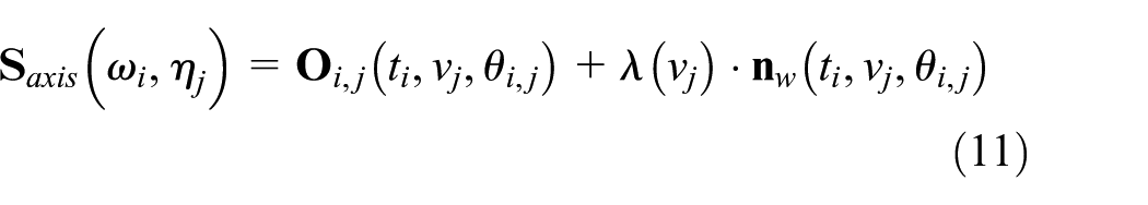
where

where both

where
Equations (9)–(11) together determine the normal mapping between envelope surface and tool axis trajectory surface. In other words, the tool axis trajectory surface is the normal mapping surface of the tool envelope surface.
Note that although the right-hand side of equation (11) determines a point on tool axis trajectory surface
Analytical expression of flank milling error under normal mapping
The characteristic point

One may note that the error in this article is defined as the distance of considered point on design surface to envelope surface, which is measured along the normal direction of the envelope surface.

Characteristic points and corresponding map points.

Error of flank milling.
However, the point pair “intersection point

From the perspective of calculation, there is no difference between the two definition of flank milling error, that is, equations (14) and (15). However, the meaning behind is different. First, the error defined in equation (14) is unsigned, but equation (15) determines a signed flank milling error. As shown in Figure 3, the error is negative if the characteristic point is located inside the envelope surface and positive if the characteristic point lies on the exterior of the envelope surface. Second, shape control parameters of tool axis trajectory surface and tool geometry are built into signed error defined by equation (15), which provides a great convenience for the subsequent optimization of tool size and tool path.
In addition, it is necessary to calculate the intersection of a designed surface and a line to obtain the point
Model for synchronous optimization of tool size and tool path with bounded constraints
Basic idea of optimizing tool size and tool path
Based on normal mapping, the correspondence between the surface pair “design ruled surface–envelope surface–tool axis trajectory surface” is established in section “Normal mapping between tool axis trajectory surface and envelope surface,” and then, this correspondence is utilized to obtain the signed flank milling error. This signed error is related to both tool size and tool path, which facilitates the optimization of tool geometry and its trajectory surface.
The basic idea is to modify control points of tool axis trajectory surface and tool size (bottom radius and half taper angle) simultaneously such that the envelope surface fitted the designed surface as much as possible. For more clarity, equations (10) and (12) are substituted into equation (15)

where
For any given sampling point
Optimization model and its solution
For a set of points

The bottom radius
The trust-region reflective optimization method,
30
which uses the interior reflective algorithm to solve the trust-region sub-problem, is a powerful approach to solve bound-constrained nonlinear minimization problems.
31
The basic idea of trust-region method is to approximate objective function
Now, we present the following algorithm to optimize tool size and tool path simultaneously for five-axis flank milling with a taper tool.
Numerical examples
In order to demonstrate the validity of the proposed method, an example of its application on flank milling of ruled surface with taper tool is supplied. The test ruled surface is taken from Zhu et al.,
25
and we refer the readers to Zhu et al.’s
25
work for the control points of the ruled surface. The parameters of taper tool chosen for simulation are as follows: bottom radius
Control points of the two directrices of the initial tool axis trajectory surface.

50 × 30 points are sampled from the envelope surface formed by cutting tool. The optimal bottom radius is

Straight generatrix of taper tool before and after optimization.
Control points of the two directrices of the tool axis trajectory surface after optimization.

Algorithm (tool size and tool path optimization)


Tool axis trajectory surface before and after optimization.
Figures 6(a) and (b) describe the distribution of the geometric error before and after optimization. The maximum overcut error and the maximum undercut error at each cutter location before and after optimization are shown in Figures 7 and 8, respectively. It is observed that the error before optimization varies in range [–0.117113, 0.001958], whose interval length is 0.119071 mm, and the error after optimization varies in range [–0.019159, 0.007724], whose interval length is 0.026883 mm. It should be noted that the negative sign is used only to indicate overcut. We can see that the global maximum overcut error reduces from 0.117113 to 0.019159 mm, as shown in Figure 7. In addition, Figure 6(a) shows that the overcut error before optimization is dominant, and this is the reason for the smaller undercut error before optimization, as shown in Figure 8. Although the global maximum undercut error increases slightly from 0.001958 to 0.007724 mm, the length of error interval greatly decreases from 0.119071 to 0.026883 mm.

Distribution of geometric error (a) before and (b) after optimization.

Maximum overcut error at each cutter location before and after optimization.

Maximum undercut error at each cutter location before and after optimization.
Conclusion
In this article, an approach is presented to simultaneously optimize the tool size and tool path for five-axis flank milling of a ruled surface with a taper tool. The normal mapping is introduced to associate the tool axis trajectory surface with tool envelope surface, and we draw the conclusion that tool axis trajectory surface is the normal mapping surface of tool envelope surface. On this basis, the correspondence between the surface pair “design ruled surface–envelope surface–tool axis trajectory surface” is established, and then, it is used to obtain the signed flank milling error, which incorporates the shape control parameters of both tool path and tool geometry. In addition, the basic idea of reducing flank milling error is to deform tool path or tool size so that the associated tool envelope surface approximates to the designed surface as closely as possible. Based on this idea, the signed flank milling error is utilized to formulate the mathematical model for synchronous optimization of tool size and tool path with bounded constraints, and the trust-region-reflective least-squares method is used to solve this constrained optimization problem.
In addition, if the B-spline curve is used to represent the generatrix of tool and the associated cutter rotation surface, the proposed method can be extended to general rotary tools.
Footnotes
Academic Editor: Kuei Hu Chang
Declaration of conflicting interests
The author(s) declared no potential conflicts of interest with respect to the research, authorship, and/or publication of this article.
Funding
The author(s) received no financial support for the research, authorship, and/or publication of this article.