
Abstract
Adding micro-texture and lubricant on the rake face of tool is an effective way to reduce the friction and resistance between the tool and the chip, which can greatly improve the cutting performance. At present, in the process of cutting lubrication simulation of textured tool, it is difficult to establish accurate simulation model because of the complexity of micro fluid flow and cutting process. In this paper, the micro clearance textured boundary lubrication cutting model is established. The R-SGFEM is employed to solve the lubrication flow field to get the friction coefficient, which is substituted to software AdvantEdge to obtain the cutting results. This simulation method is verified by experimental research and theoretical analysis. Then, the influence of texture geometry parameters and cutting parameters on cutting effect is studied to reveal the interaction mechanism between the rake face of textured tool and chips.
Introduction
In order to achieve efficient machining of difficult to machine materials in aerospace, medical and health, bioelectronics and other fields, reduce the friction damage between cutting tools and chips, the cutting lubrication technology of textured cutting tools came into being. Because of the micro scale characteristics of texture and cutting clearance, the flow of lubricating oil needs to consider the micro size effect. It is an important research direction to explore the cutting process combined with the surface texture and micro fluid lubrication of cutting tools. By using the application of textured surface in friction field for reference, many scholars add texture to the tool surface to reduce friction and drag between the tool and chip, and improve the cutting performance of the tool.1,2
There are many researches on the size and shape of tool surface texture, the techniques of constructing different textures, cutting methods, lubrication methods, etc. 3 The shape of most of the texture is summarized and found that its two-dimensional cross-section can be divided into four types: rectangular, circular, triangular, and prismatic. Mishra et al. 4 used three-dimensional finite element to study the influence of different geometry (circle, square, triangle, and ellipse), area density, and depth of the rake surface texture on the dry cutting of Titanium alloy. It was found that the area density of texture has more obvious influence on the cutting force than the shape of texture. Chen et al. 5 processed the misaligned rectangular micro-texture on the surface of aluminum alloy by micro-milling. Different types of textures can be processed in a variety of ways, such as micro cutting,6–8 EDM, 9 photolithography, 10 ion etching,11,12 laser machining,13,14 etc. Different machining methods will affect the surface properties, thus affecting the boundary slip length. Among them, Laser processing changes the scanning speed and other processing parameters, and can process various shapes of textures on materials with different hardness. In addition, for softer metal materials, rectangular texture, circular texture, and prismatic texture can be machined by high-speed micro-milling with end mills, spherical mills, and conical mills, respectively. Xing et al. 15 studied the effects of laser processing parameters on surface quality, microgroove size, and surface roughness. Wang et al. 16 used finite element method to numerically study the cutting performance of tools with different micro-groove shapes.
Cutting methods can be divided into dry cutting, fluid lubrication, and minimum quantity lubrication (MQL). Liu et al. 17 carried out Titanium alloy cutting experiments on WC-10Ni3Al and WC-8Co micro texture cutting tools. They found that the micro texture on the rake face can effectively reduce cutting force, cutting temperature, and adhesion, so as to improve tool life. The effect is particularly obvious at higher cutting speed. Ge et al. 18 investigated the effect of the texture position on the contact characteristics of the cuttings. Singh et al. 19 carried out turning experiments on dry cutting, minimum quantity lubrication (MQL), mixed nano particle minimum quantity lubrication (NMQL), and filled graphene particle cutting with textured tools. The results showed that the NMQL, MQL, and graphene particle followed by dry cutting produced the maximum tool life, lower cutting force, and minimum cutting temperature. The effects of cutting parameters and different tool coatings (AlTiN, nACo, and TiSiN) on surface roughness and burr formation during micromachining of Inconel 718 were studied. 20
Under different lubrication cutting conditions, texture tools can effectively improve cutting performance. Zhou et al. 21 processed the micro groove texture parallel to the main cutting edge on the rake face of the uncoated tool, and carried out the cutting fluid lubrication experiment, revealing the mechanism of the coupling effect between the micro structure and the nano fluid. Ghosh and Rao 22 shows the principle of MQL high pressure spray lubrication. The cutting fluid is continuous liquid near the cutting edge. When the distance between the chip and the rake face is far away, the droplet will appear foggy. Therefore, during the cutting process, the lubrication of the front end of the tool can be regarded as continuous liquid lubrication, but the fluid effect is not considered in the specific cutting energy model. In conclusion, the current cutting simulation focuses on the dry cutting of Titanium alloy, it is necessary to explore an effective method of fluid lubrication cutting simulation. Ge et al. 23 carried out a full film lubrication cutting experiment on the textured and untextured rake face. They found that the lubricating fluid can continuously penetrate into the contact area through the micro groove texture on the rake face. Mikolajczyk24,25 studied the influence of minimum thickness cutting layer on surface roughness in the turning process. In particular, the influence of inclined cutting conditions on MUCT phenomenon when the dip edge angle (50° ≤ λs ≤ 85°) is extremely high.
Because of the high cost and time-consuming of experimental research, a large number of cutting simulation methods are proposed to simulate the cutting process. Krishnaraj 26 used software AdvantEdge to calculate the orthogonal dry cutting of Titanium alloy. It was stated that high speed, low feed speed, and large rake angle were suitable to reduce the cutting force and cutting temperature in the turning process. The reliability of AdvantEdge to simulate the high-speed machining of titanium alloy was high. Jackson et al. 27 studied the chip formation of micro machining Ti-6Al-4V by using AdvantEdge. It was found that when the main cutting force is greater than the thrust, chips will be produced. When the main cutting force is less than the thrust, burrs will be produced. The effect of chip formation mechanism on the surface integrity of medical materials was explained. One of the most important purposes of adding texture to the tool surface is to reduce friction. Cutting fluid, as a lubricant, can reduce the cutting temperature while adjusting the friction coefficient. However, there are still many difficulties to simulate the friction process by considering the lubricant. The cutting fluid is a liquid, and its simulation process needs to be solved by using the hydrodynamic equation. Because the distance between the rake face and chips is very small, the micro fluid effect needs to be considered. During the cutting process, the elastic, plastic deformation, and fracture of the workpiece need to be considered. At present, the simulation software used in the cutting field mainly includes DEFORM, ABAQUS, ANSYS, and AdvantEdge. AdvantEdge is a finite element numerical simulation software for the field of cutting processing, which can simulate the process of turning, milling, drilling, broaching, etc., so as to obtain the cutting force, cutting heat, stress and strain, and tool wear in the machining process. Compared with other finite element software, AdvantEdge interface is easy to operate, easy to human-computer interaction, and more suitable for simulation of two-dimensional cutting process. 28 At present, ANSYS and others can carry out simple fluid structure coupling calculation, but in the cutting field, the solution accuracy is not high and the application is less. Therefore, this paper mainly uses AdvantEdge software to simulate cutting.
Therefore, the purpose of this paper is to analyze the influence of textured geometric parameters of rake face on lubrication flow field under different slip lengths in order to improve cutting lubrication performance. An effective microfluidic simulation method, R-SGFEM, 29 is used to solve the microfluidic flow process between texture and chip, and obtain the friction coefficient. Then, the cutting process is simulated by the cutting simulation software AdvantEdge, and the friction coefficient is obtained by R-SGFEM. With the help of experimental research, 30 this cutting lubrication simulation method is proved to be effective. Furthermore, the influences of texture geometry parameters, slip length, and cutting parameters on cutting effect are studied in this paper.
Methods
Establishment of two-dimensional texture model
In order to meet the functional requirements of textured surface in different occasions, texture is processed into various shapes by various processing methods. In the actual three-dimensional textured surface, the texture is usually processed into regular shapes such as cylinder, cube, groove, etc. The simulation of three-dimensional region needs high calculation cost, including economic cost and time cost. The simulation analysis of two-dimensional cross-section can get the general calculation data and save the calculation cost, so it is of great significance to establish the calculation model of two-dimensional cross-section flow field of textured boundary.
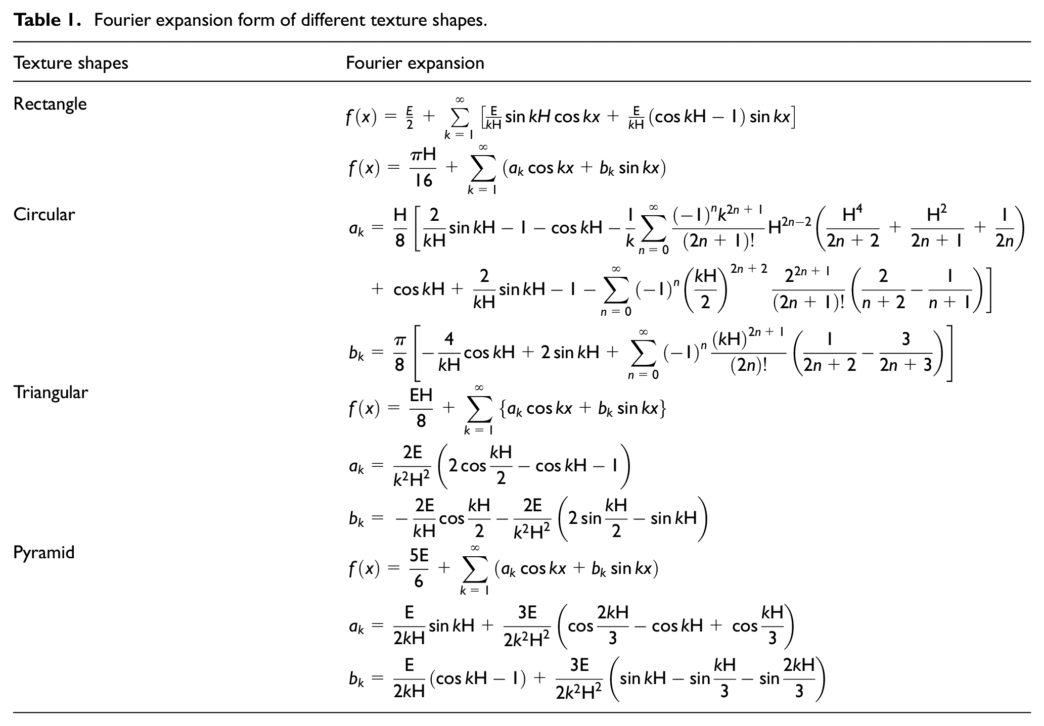
According to the two-dimensional cross-section of the texture, it can be divided into four types: rectangle, circle, triangle, and pyramid, as shown in Figure 1. Among them, the most common shape is rectangle, as shown in Figure 1(a). Suppose that the depth of texture is D, the width of texture is W, and the spacing is S. The expression of the first period is:

Similarly, for the circular, triangular, and pyramid texture shown in Figure 1(b) to (d), respectively, assuming that the diameter or width of the texture is W, the distance of each edge length on the x-axis is equal, the spacing of the texture is S, and the texture depth is D, the expression of their first period is divided into:


Among them, equations (2)–(4) are expressions of circular, triangular, and pyramid texture respectively.

Classification of cross section shape of two-dimensional texture: (a) rectangle, (b) circle, (c) triangle, and (d) pyramid.
In order to express the texture boundary with multiple periods and unify the formula forms of multiple texture shapes, and facilitate the modeling and solution, Fourier expansion is carried out for the texture with the above shapes. Assuming W = S = D, the Fourier expansion form of equations (1)–(4) can be written as follows:
In Table 1, for the convenience of expression, a k and b k are used to express the coefficients of cosine and sine terms for easy calculation.
Fourier expansion form of different texture shapes.
The solution of fluid field of lubrication and coefficient of friction
In the lubrication cutting process of textured tool, the cutting fluid flows in the gap between the rake face and chip and inside the texture under the influence of chip flow. The flow form is affected by the texture shape and size. As shown in Figure 2, the surface of cutting tool is processed with different size and shape texture. During cutting, the chip moves along the rake face, which drives the flow of cutting fluid. The flow pattern of the liquid changes with the texture shape and size. For example, for rectangular texture, a small aspect ratio will make the flow line of cutting fluid slightly concave inward, and the flow pattern will not change much. When the ratio of depth to width is large, there will be recycling phenomenon and even vortex in the texture. At the same time, the lubrication gap between the chip and the rake face is small, which is usually micron level, so the boundary slip effect of the microchannel needs to be considered. Therefore, in this paper, R-SGFEM is used to solve the fluid flow in the lubrication gap, and the friction coefficient is obtained. Then, the friction coefficient is substituted into the cutting simulation software AdvantEdge to solve the cutting process.
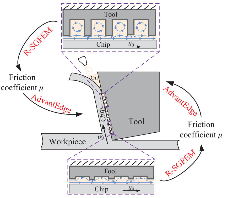
Schematic diagram of textured tool lubrication cutting system.
In order to solve the friction coefficient, it is necessary to solve the pressure and velocity of the lubrication flow field, which involves the flow problem of micro fluid and the change of boundary shape. Therefore, R-SGFEM 29 is used to calculate the fluid region in this paper. Considering the effect of slip boundary, the Reynolds equation is used to solve the boundary slip velocity. Then the Galerkin finite element method is used to solve the Stokes equation to get the pressure and velocity of the lubrication flow field. The boundary pressure and shear force are integrated respectively to obtain the bearing capacity and friction force. Finally, the friction coefficient is obtained. Figure 3 shows the flow field model of textured tool cutting lubrication.

Lubrication flow field model of textured tool.
Among all kinds of texture shapes on the front face of cutting tool, rectangle texture is the most widely used. In this paper, the rectangular texture is studied. As shown in Figure 3, the depth, width, and spacing of texture are D, W, and S respectively. The movement velocity of chip is u0, and the half depth of chip to texture is h0. Assuming that the texture presents regular arrangement W = S = H, and refer to Section “Establishment of two-dimensional texture model” for the derivation of Fourier expansion of the rectangular texture, the upper boundary of texture can be expressed as:

where h is the thickness of lubricant.
Because the distance between the chip and the rake face is very small, it is only micrometer level. When solving the flow field, the macroscopic fluid flow equation can’t be fully applied, so the slip boundary condition should be considered. The chip moves along the direction perpendicular to the cutting edge, and the moving speed is mainly concentrated in this direction. Therefore, only the boundary slip effect along the x direction is considered. As shown in Figure 3, green line represents slip boundary, black line represents no slip boundary. The slip velocity u s at the boundary is used to express the difference between the boundary velocity and the fluid velocity near the boundary. The slip length at the boundary is expressed as b. The relationship between them can be expressed as 31 :

where u is the velocity of the lubricant in the x direction.
According to R-SGFEM, the shear force at the boundary can be expressed as:

where η is the viscosity of lubricant.
And the pressure is solved by Stokes system using Galerkin finite element method. The governing equation can be expressed as:

where p is the pressure of lubrication flow field, and
Then, the pressure and shear force near boundary can be integrated to obtain the bearing capacity W and friction force F f . After that, the friction coefficient μ can be obtain by:

The simulation of cutting process
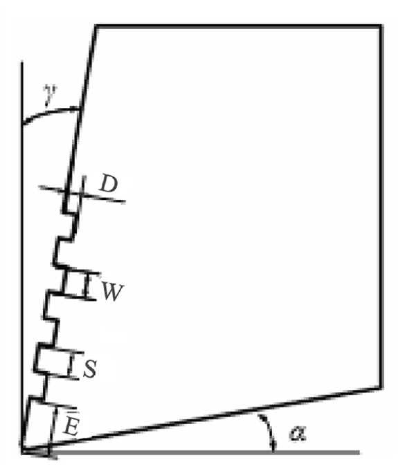
In order to match with the rectangular texture lubrication model of the rake face solved by R-SGFEM, the rectangular texture tool model is established in cutting simulation. Figure 4 shows a two-dimensional textured tool model. γ is the rake angle of the tool, α is the relief angle of the tool. W, S, and D represent the width, spacing, and depth of texture respectively. E is the distance between the first texture and the cutting edge. The size of the workpiece is 5 mm long and 2 mm wide, and the cutting length is 6 mm to ensure that the cutter can cut the chips completely.
Two-dimensional textured tool model.
In the calculation of AdvantagEdge, the workpiece adopts the method of grid adaptive division, which makes the grid at the cutting edge more compact in the cutting process. The grid is encrypted near the cutting edge with the cutting edge moving forward. The grid shape is adjusted continuously in the calculation process to avoid grid distortion. The number of grids in the non-cutting area is smaller, so as to ensure the accuracy of the calculation results and save the calculation time, and easy to form chips. Figure 5 shows the triangular mesh generation of the initial stage cutting model.

Mesh generation of cutting model.
After setting the cutting parameters and friction coefficient, submit the calculation. In the process of cutting simulation, the tool is fixed and the workpiece moves from left to right at a constant speed along the horizontal direction. In the Figure 5, the x direction is the main cutting force direction and the y direction is the axial cutting force direction.
In the cutting process, Coulomb friction law is used to calculate the cutting process by setting the friction coefficient between the rake face and chip as a constant. The principle is shown in equation (9). At present, the friction coefficient is mostly determined by cutting force and tool angle, as shown in equation (10). 30

where β is the friction angle, F r is the radial cutting force, and F x is the main cutting force.
Nowadays, the main way to obtain cutting force is cutting experiment, which puts forward high requirements for simulation conditions. If the cutting force needs to be measured by experiment before each simulation, the experiment cost will be increased and the advantage of simulation calculation will be reduced. Therefore, this paper combines R-SGFEM and AdvantEdge software to simulate the cutting lubrication process. Through R-SGFEM, the friction coefficient between textured tool and chip is obtained. Then the friction coefficient is input into AdvantEdge for cutting simulation to obtain cutting force, cutting temperature and stress, etc. The calculation flow chart is shown in Figure 6.

Flow chart of cutting lubrication simulation calculation.
Results and discussions
Pressure measurement of textured boundary lubricating oil film
In order to match the experimental and simulation models studied, this paper designed and built a lubricating oil film pressure measurement platform as shown in Figure 7. The experimental instruments mainly include: the displacement table (PDV PT110-25-65), laser displacement sensor (Keyence LK-G30), displacement monitoring board, data acquisition device, micro fluid pressure sensor (Labsmith, uPS01-T116-PKG). Among them, the displacement table is used to adjust the clearance between the upper and lower friction samples. The laser displacement sensor and displacement monitoring board are used to monitor the thickness of the oil film. The oil film pressure is measured by a data acquisition device and the microfluidic pressure sensor.
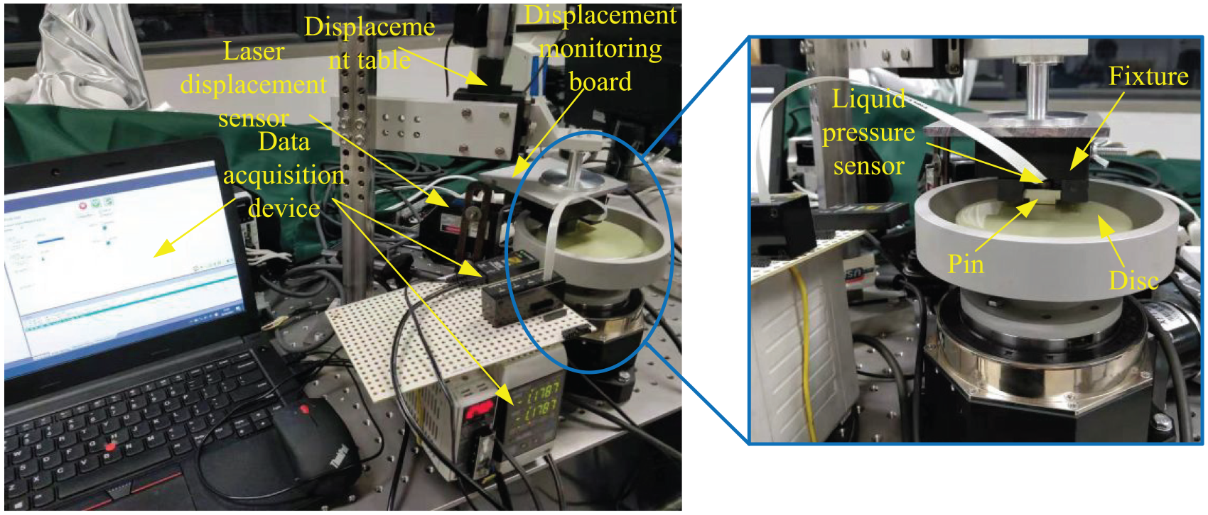
Lubricating oil film pressure measuring device.
The inner part of the textured sample is drilled and tapped to match the micro fluid pressure sensor, and then the pressure sensor is screwed into the upper sample, its bottom end is flush with the inner boundary of the texture. After the upper sample is tightened with a clamp, the lower friction sample is rotated to measure the pressure of the micro clearance oil film liquid. The measuring range of microfluidic pressure sensor is 0–250 kPa, and the accuracy is 1 Pa. The sensor is connected to the converter on the operating platform through the connecting wire, and the other end is connected to the computer through the USB interface. When the oil film flows, the pressure sensor receives the pressure signal, displays the pressure value change on the computer in real time, and fits the pressure signal of the position measured by the pressure sensor. Then the average value is obtained. As the pressure boundary condition here, it is substituted into the R-SGFEM. The flow field value and friction coefficient are corrected, and the friction coefficient is substituted into AdvantEdge for cutting simulation.
Verification of cutting lubrication model
In order to match the texture size of the cutting tool in the cutting experiment, the design parameters of the texture are: width W = 30 μm, depth D = 16 μm, spacing S = 20 μm, texture distance from the cutting edge E = 250 μm, a total of four rectangular textures, which are consistent with the lubrication simulation model in R-SGFEM. According to the type of material, the thickness of oil film is about 2 μm, and the sliding length is 11.5 μm. The cutting simulation parameters are: cutting speed 150 m/min, cutting depth 0.5 mm, feed speed 0.198 mm/rev, tool rake angle γ = −5°, cutting material H13 hot film steel, hardness 55 HRC. In the process of cutting lubrication simulation, the control of the lubrication effect is mainly reflected in the friction coefficient, so it is assumed that there is a layer of lubrication film on the texture surface, and the lubrication effect is reflected by controlling the friction coefficient, which is calculated by R-SGFEM. The simulation results and experimental data are shown in Table 2. The experimental data in Table 2 are obtained from the cutting experimental results of Ge et al. 23 The experimental mode is liquid lubrication turning, and the texture processing mode is laser processing. The texture parameters, cutting parameters, and boundary conditions of simulation and experimental models are the same.
Comparison of simulation and experimental results.

Figure 8 shows the grid diagram of cutting simulation with friction coefficient of 0.54. The grid near the cutting edge is dense, and the grid at the unmachined part is sparse, which saves calculation time while ensuring the simulation accuracy. There is a small gap between the chip and the texture surface of the tool, and intermittent friction occurs. The chip width is about 268.3 μm. Comparing the simulation and experimental data in Table 2, under the same texture parameters, the chip width, axial cutting force, main cutting force, and friction coefficient of the simulation results are slightly lower than the experimental data, and their errors are all within 10%. Therefore, the simulation method used in this paper is feasible.

The simulation results of experimental model.
The friction coefficient used in cutting simulation is 0.54, which is calculated according to the R-SGFEM. Figure 8 shows the pressure distribution and velocity distribution of the lubricating fluid in the cutting experimental model. The left end is close to the cutting edge, and the right end is the chip outlet direction. Smaller lubrication clearance and relatively larger texture depth make the pressure fluctuation amplitude of the lubricating fluid increase, which produces more obvious normal pressure on the chip. The pressure value near the cutting edge increases rapidly, which forms larger pressure on the chip and promotes the chip separation. However, with the pressure of the chip moving toward the outlet decreasing, the chip gradually separates from the workpiece and the rake face. The effect of normal pressure is weakened, so the tool texture plays an obvious role in promoting the separation of chip and rake face in the process of lubrication cutting. From the velocity nephogram Figure 8, it can be seen that the velocity of the lubricant will be lower than the chip velocity due to the existence of boundary slip (the differential slip velocity depends on the slip length). A small cutting lubrication clearance makes the flow velocity of the lubricating fluid on the rake face and the chip surface not differ greatly. The flow velocity of the lubricating fluid on the chip surface is about 1.35 m/s, and the flow velocity of the lubricating fluid near the rake face is about 1.15 m/s. The appearance of texture reduces the flow velocity of the lubricating fluid. With the change of the size of the tool surface texture, the lubricating oil has different flow forms in the texture. When the texture depth is small, the streamline will sag slightly inward. As the depth increases, the lubricating oil begins to flow in the opposite direction; When the depth to width ratio is large, there will even be vortices inside the texture. This is consistent with the phenomenon described in literature. 29
Influence of texture and cutting parameters on cutting lubrication effect
By controlling the change of texture size, boundary slip length, and cutting parameters, the cutting lubrication effect of texture cutter on Ti-6Al-4V was studied in this paper. The coupling effect of texture, boundary slip, and cutting process was explored. The influence of the surface texture of the cutting tool on the cutting effect is studied. The cutting parameters are: feed speed 0.15 mm/rev, cutting thickness 0.5 mm, cutting speed 120 m/min. Titanium alloy Ti-6Al-4V is selected as workpiece materials. Cemented carbide is selected as tool materials. Figure 9 shows the cutting state when the texture depth is 20 μm. The chips are zigzag to the unfinished surface, and the cutting gap between the rake face and the chips is always small. The workpiece grid is concentrated on the main cutting edge to ensure the calculation accuracy, and the other parts are large grids to save the calculation time. In order to verify the accuracy of the simulation model, experiments with the same material and cutting parameters were designed, as shown in Figure 10. The experimental equipment includes CNC lathe, cutting tool holder (PCLNR2525M12), diamond texture carbide blade, and texture parameters are consistent with the simulation. The remaining equipment includes a data acquisition box and a dynamometer. Workpiece selection of titanium alloy Ti-6Al-4V (Ø70 × L250 mm).

Cutting process for texture depth 20 µm.

Cutting experiment.
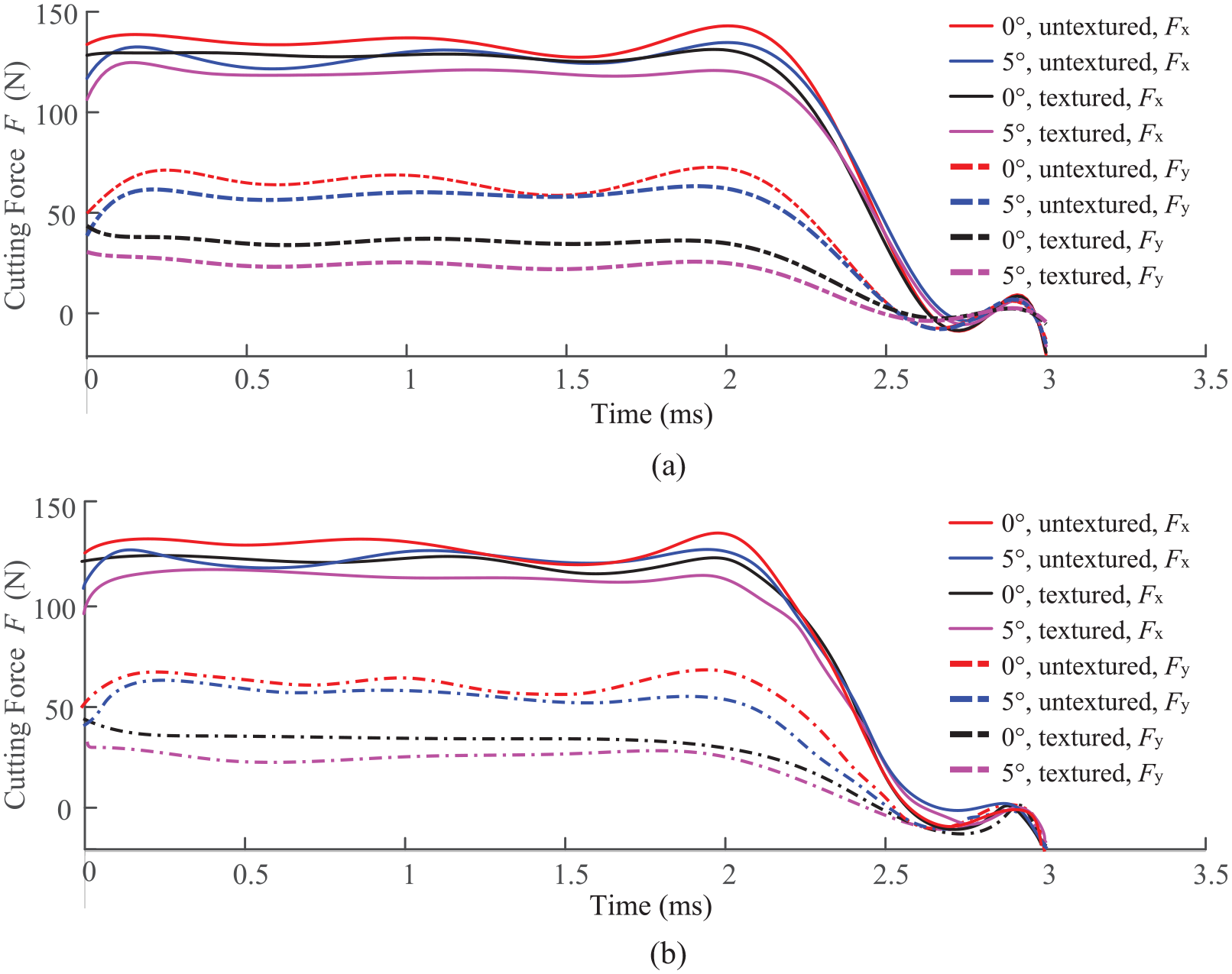
In order to compare the influence of tool surface texture on cutting force, the cutting simulation calculation is carried out for textured tool and untextured tool under the same cutting conditions respectively. Figure 10 shows the change of cutting force and maximum cutting temperature with time in x and y directions when the friction coefficient is 0.3 and the rake angle are 0° and 5°. The length of the workpiece is 5 mm, the cutting length is 6 mm, the cutting speed is 120 m/min, the texture distance from the cutting edge is E = 200 μm, and the cutter cuts out the workpiece in 0.0025 s. At 0.0023 s, the chip is basically separated from the workpiece, and the forces in x and y directions begin to decrease rapidly. When the tool cuts out the workpiece, F x fluctuates slightly. Then, the cutting force returns to zero. The trend of chip flow decreases gradually from the positive y direction, falling down when leaving the tool, which causes the tool to receive a slightly downward force, resulting in a small amount of negative F y . The cutting force returns to zero after the tool cuts out, completing the cutting process. However, the maximum temperature of the tool surface increases rapidly to a stable value with the cutting process, and then decreases gradually after the cutting process.
In Figure 11(a), it can be seen that the cutting force F x of different tools fluctuates within their fixed range. The fluctuation range of the force is approximately the same, while the formation of serrated chips results in a large fluctuation range. Figure 11(b) shows the fluctuation of the cutting force F y , and their sizes are obviously different. From small to large, they are the textured tool with a rake angle of 5°, the textured tool with a rake angle of 0°, the untextured tool with a rake angle of 5°, and the untextured tool with a rake angle of 0°. That shows that the cutting force in the y direction can be reduced by using a larger rake angle and adding texture, while the cutting force between the chip and the rake face of the tool can be reduced by using a larger rake angle and adding texture. The friction mainly occurs in the y direction, so adding texture can reduce the friction coefficient. Figure 11(c) shows that the peak temperature of cutting edge changes with cutting time in four cases without considering cooling. In each case, although the temperature fluctuates with time, the two curves without texture basically cross each other, showing a lower value, while the two cutting temperature curves of textured tool cross each other, showing a higher value. However, the tool texture makes the cutting temperature slightly higher.

Cutting force and temperature of different tool rake angle and texture surface versus cutting time: (a) cutting force F x , (b) cutting force F y , and (c) the highest temperature versus time.
The signal of cutting force is relatively disordered. In order to directly compare the values of cutting force in Figure 11(a) and (b), the curve is fitted by the 10th degree polynomial, as shown in Figure 12(a). Figure 12(b) shows the fitting results of cutting experimental data. The figure shows that at the beginning of cutting, the force of the tool with rake angle of 5° increases rapidly in both directions and then decreases slightly, showing a small peak value. Then, it gradually tends to be flat, among which the x direction is the most obvious, while the cutting force produced by the tool with rake angle of 0° changes more steadily. After fitting, the trend of cutting force F x can be seen clearly. The cutting force of textured tool with 0° rake angle and 5° rake angle is the largest. The cutting force of textured tool with 5° rake angle is the smallest. The other two tools slightly coincide in the middle position, which shows that the cutting force F x can be affected by the angle and texture of tool together. The larger rake angle and texture can slightly reduce it. The trend is consistent with the law of F y . But the difference between the forces in x direction is much smaller than that in y direction, so the influence of rake angle and texture on the forces in y direction is more obvious. In addition, the experimental results agree well with the simulation results. Due to the inevitable factors such as the setting of the simulation material attribute parameters, the division of the grid and the wear of the tool during the experiment, the simulation results are inconsistent.
Fitting curve of cutting force for different tool rake angle and texture surface: (a) results obtained through simulation and (b) results obtained through experiments.
In order to explore the influence of texture size and lubrication clearance on friction coefficient and cutting force, the friction coefficient and cutting force are calculated when texture depth is 20 μm, sliding length is 11.5 μm, lubrication clearance is 5, 8, and 10 μm, texture width and spacing are 50 and 100 μm, and Figures 13 and 14 are obtained.
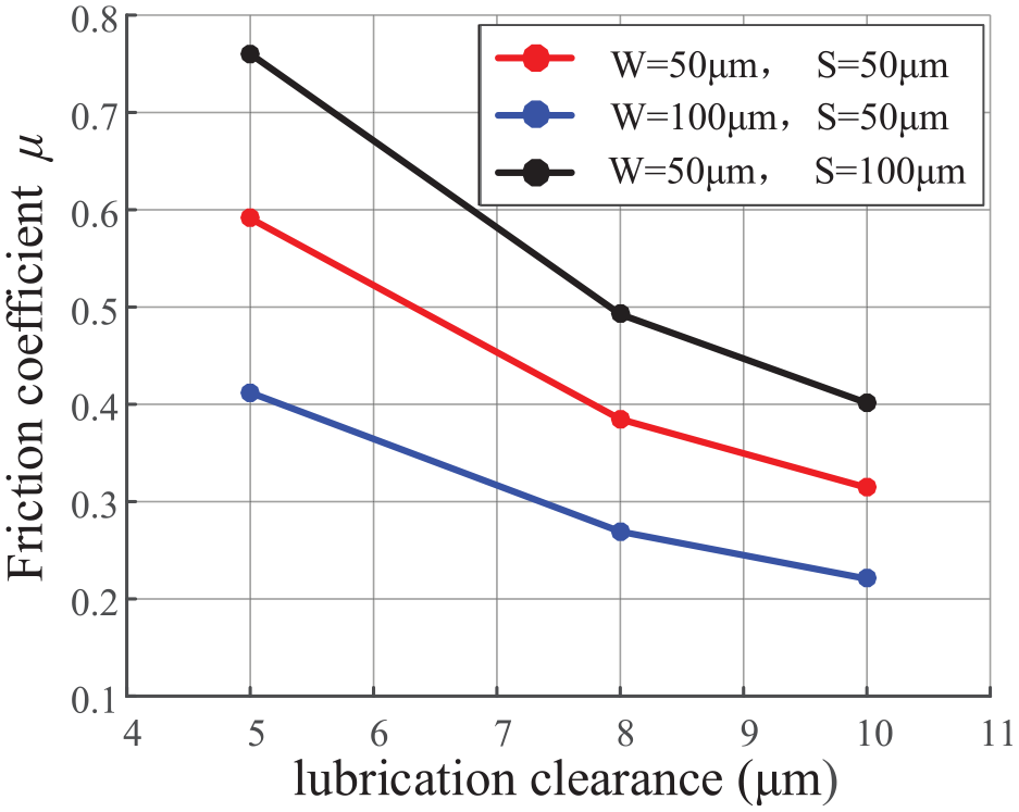
Friction coefficient versus lubrication clearance.

Cutting force versus lubrication clearance (W = 50 μm, S = 50 μm).
Take the friction coefficients of 0.5912, 0.3847, and 0.3143 when the texture width and depth are both 50 μm, and substitute them into the AdvantEdge software to calculate the cutting force. The results are shown in Figure 14. With the increase of lubrication clearance, the change of F x is not obvious, but F y shows a decreasing trend, especially for the tool with rake angle of 0°. With the increase of lubrication clearance, the chip is far away from the rake face, the interaction force is weakened, and the friction force is reduced, so F y presents a downward trend. The cutting speed of workpiece along the x direction is unchanged, so F x is not affected. The rake face of the tool with a rake angle of 0° is parallel to the y direction. The friction between the chip and the rake face is reflected in the cutting force F y . The mapping of the rake face cutting force of the tool with a rake angle of 5° to the y direction is slightly reduced, and the cutting edge is sharper. The slope of this curve is smaller than that of the tool with a rake angle of 0°.
The sliding length determines the sliding speed of the lubricating fluid at the boundary, and affects the friction between the chip and the rake face. Figure 15 shows the fitting curve of the y direction cutting force F y of textured tool with a sliding length of 1–6 μm, a texture depth of 20 μm, a width and a spacing of 50 μm, and the temperature nephogram of the main cutting edge. The rake angle of the tool is 5° and the average film thickness of the lubricating oil is 10 μm. The curve in the figure shows the same change trend as Figure 12.

The change of cutting force F y with time and the temperature near the cutting edge under different slip length.
With the increase of the slip length, the fluctuation amplitude of the cutting force F y decreases and changes more smoothly with time, and the value of the cutting force also shows a decreasing trend. When b = 1, 2, 4, and 6 μm, the corresponding friction coefficients are 0.6785, 0.5260, 0.3714, and 0.2915, respectively. The smaller the slip length is, the larger the velocity difference between the two boundaries of the micro gap is, the larger the shear stress is, so the larger the friction is, the larger the fluctuation range of the cutting force is. Figure 15 shows the temperature distribution nephogram under different sliding lengths when the cutting length is 0.24 mm. It is found that a smaller sliding length will produce a larger cutting temperature, which is related to a larger friction coefficient. The larger the friction during cutting, the more intense the friction between the chip and the rake face, and more heat will be generated. Therefore, the material with better hydrophobicity can be selected when selecting the cutter surface material or coating, so as to increase the slip length, reduce the friction coefficient and the cutting heat.
In this paper, the influence of textured cutting tools on cutting force under different cutting parameters is simulated. The cutting speed, feed speed, and cutting thickness are changed to observe the influence of different tool rake angle on cutting force. Table 3 shows the relationship between cutting force and different cutting parameters, texture depth is 20 μm, width and spacing are 50 μm, and friction coefficient is 0.3.
Comparison of simulation and experimental results.

It can be seen from Table 3 that under the same cutting parameters, the cutting forces F x and F y of the tool with rake angle of 5° are smaller than those of the tool with rake angle of 0° in both directions. The increase of feed speed and cutting thickness makes the cutting forces increase, which is consistent with the law embodied by the tool without texture. With the increase of cutting speed in the range of 0–120 m/s, the cutting force shows a trend of increasing rapidly first and then decreasing gradually to a stable value. When the cutting speed reaches 20 m/min, the cutting force of tools with different rake angles basically reaches a stable value in the x and y directions. It can be seen from Table 3 that the simulation results are basically consistent with the experimental results.
In the cutting process, the rake angle of the tool determines the flow direction of the chip and affects the change of the cutting resistance. In the case of constant feed speed, the length from the first texture to the cutting edge E will determine whether the texture will produce secondary cutting on the chip. When other conditions are not changed, the decrease of rake angle will increase the possibility of texture to chip secondary cutting, and then affect the value of cutting force. Therefore, keeping the cutting speed of 120 m/min, texture depth of 20 μm, texture width and spacing of 50 μm, and feed rate of 0.15 mm/rev, this paper studies the influence relationship between the rake angle of the tool, the length of texture from the cutting edge, feed speed, and texture on the secondary cutting of chips.
In the cutting process, the rake angle determines the flow direction of the chip and affects the change of the cutting resistance. In the case of constant feed speed, the length from the first texture to the cutting edge E will determine whether the texture will produce secondary cutting on the chip. When other conditions are not changed, the decrease of rake angle will increase the possibility of texture to chip secondary cutting, and then affect the value of cutting force. Therefore, this paper controls the cutting speed of 120 m/min, texture depth of 20 μm, texture width and spacing of 50 μm, and feed rate of 0.15 mm/rev. The influence of rake angle, texture to cutting edge length, feed speed, and texture on the secondary cutting of chips is studied.
Figure 16 shows the change of the cutting forces F x and F y in x and y directions with the friction coefficient when E = 100, 150, and 200 μm at different tool angles. Because the cutting forces are affected by vibration and other factors in the cutting process, the cutting process is not a constant value. This paper takes the average value of the cutting forces in a relatively stable state.

Cutting force versus friction coefficient with different rake angles: (a) E = 100 μm, (b) E = 150 μm, and (c) E = 200 μm.
It can be seen from Figure 16 that the change trend of force size is the same in three cases. Under different friction coefficients, the order of four cutting forces from small to large is: F y of rake angle 5°, F y of rake angle 0°, F x of rake angle 5°, F x of rake angle 0°. The cutting force of rake angle 5° is smaller than that of 0°. On the one hand, the rake angle of 5° cutter makes the chip move smoothly along the rake face. The flow resistance of the chip is reduced, the bonding area is easier to be cut by the sharp cutter, the thrust required in x direction is smaller, and the friction in y direction is smaller, so the cutting force required is smaller. In addition, the tool with a smaller angle contacts the chip for a longer time during cutting, and the chip is not easy to separate from the rake face. Meanwhile, the texture of the tool surface will be more likely to contact with the chip, so that the texture has a more obvious effect on friction reduction and affects the change of cutting force. Therefore, it is effective to choose a larger tool rake angle to reduce the cutting force.
When the friction coefficient and the distance between texture and cutting edge are changed, the cutting force will change, but most of them are concentrated near the fixed value. From small to large, they are 35, 50, 130, and 145 N. There is no obvious change in the whole fluctuation range of the force, but when it comes to each force, it can be found that the friction coefficient and the length of the texture distance from the cutting edge will have an impact on the change of the force, especially on the cutting force in the y direction. When the friction coefficient is 0.3, with the increase of E from 100 to 200 μm, the F y value of tool with 0° rake angle decreases from 60 to 40 N, and the F y value of tool with 5° rake angle decreases from 40 to 30 N. With the increase of the texture distance from the cutting edge, the possibility of chip entering the texture interior decreases, and the texture will not continuously cut the chip. When E is greater than the feed, the chip will not enter the texture interior in most cases, and the increase of cutting force will not produce a promoting effect, so F y is the minimum when E = 200 μm.
From Figure 16(c), it can be seen that with the increase of friction coefficient, F y shows a more obvious increase trend, while its fluctuation in the first two figures is relatively stable. The distance between the texture and the cutting edge is E = 200 μm, which is greater than the feed rate of 150 μm/rev. Therefore, for a small friction coefficient, there will be no contact between the chip and the texture during the whole cutting process. The texture will not produce a direct cutting force on the chip, so the cutting force is small. When the friction coefficient increases, the combination of chip and rake face becomes closer, the friction becomes larger. It is easier to occur friction. It is not easy to separate from cutter face. When cutting, chip enters into texture, resulting in secondary cutting, and the cutting force increases. In Figure 16(a) and (b), there will always be a second cutting of the first texture, so the change of cutting force is relatively stable.
In order to intuitively find the secondary cutting state of texture on chip, explore the reasons for the change of cutting force, and compare the chip shapes under different cutting conditions, this paper calculates the cutting stress nephogram when the chip first contacts the unprocessed surface when the friction coefficient is 0.3, as shown in Figure 17. It shows the diameter of the curl arc at the root of the sawtooth when the top of the chip contacts the unfinished surface for the first time, and the red arrow represents the direction of cutting motion.
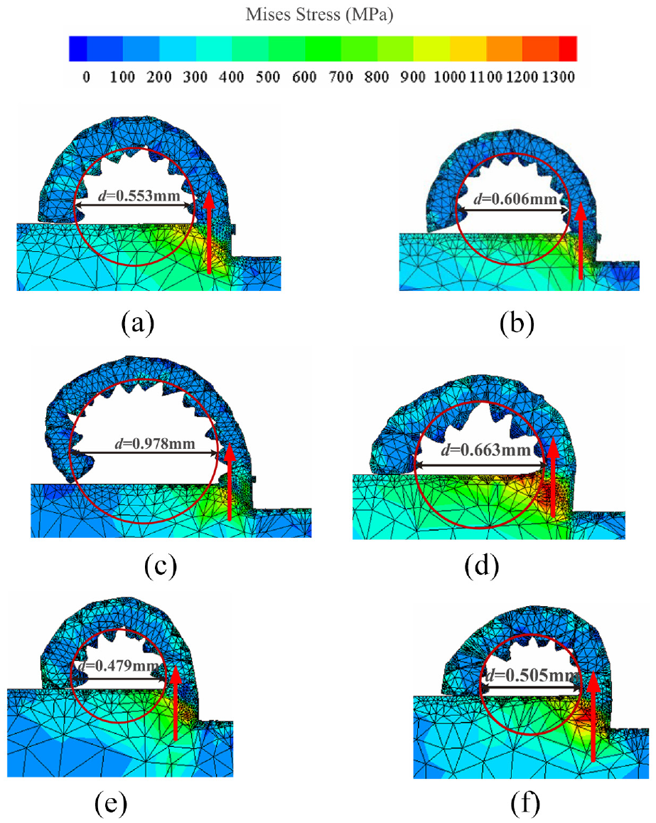
Cutting process of textured tool and diameter of chip curl (friction coefficient 0.3): (a) E = 100 μm, rake angle 0°, (b) E = 100 μm, rake angle 5°, (c) E = 150 μm, rake angle 0°, (d) E = 150 μm, rake angle 5°, (e) E = 200 μm, rake angle 0°, and (f) E = 200 μm, rake angle 5°.
From Figure 17, it can be clearly observed that in the cutting process, each deformation area, in which the stress in the first deformation area at the root of chip is the largest, plastic deformation and shear slip occur in this area. The smaller the chip curl diameter is, the more obvious the change of stress value is. When the chips flow out, there is extrusion and friction between the chips and rake face of the tool, which results in deformation. When E = 100 and 150 μm, the second cutting occurs between the first texture on the tool surface and the chip. When E = 200 μm, the texture does not cut the chip, which can further explain the change trend of cutting force in Figure 16.
Compared with the chip crimp diameter in Figure 17, it is found that when E = 100 μm, the chip crimp diameter is the smallest, followed by E = 200 μm, and the largest diameter appears at E = 150 μm. It can be seen that the chip crimp diameter does not increase linearly with the texture distance from the cutting edge length E. When E = 100 μm, the diameter of chip curl is about d = 0.58 mm, and the distance between the first texture and the cutting edge is less than 150 μm/rev. When E = 150 μm, the diameter of chip curl increases significantly. The length of the first texture from the cutting edge E is equal to the feed per revolution. After passing through the bonding area, the chip contacts with the texture and is cut twice by the texture. After passing through the flat rake face, the chip is pushed by the texture surface and grows up gradually to form the largest chip diameter. When E = 200 μm, the diameter of chip curl is about d = 0.49 mm, and the distance between texture and cutting edge is longer than the feed per revolution. After the chip and workpiece are separated at the cutting edge, they are pushed by the rake face, separated from the rake face, without secondary contact with texture, and the diameter of chip slightly decreases. Therefore, the maximum chip curl diameter is produced when the length of texture distance between cutting edge and feed per revolution are the same.
When E = 100 or 200 μm, the tool with rake angle of 5° has larger chip curl diameter than the tool with rake angle of 0°. The difference between chip shape and chip curl diameter caused by tool angle change is basically the same. When the rake angle is 0°, the chip flows along the rake face and grows vertically upward, which will not enter into the quadrant where the cutter is located. Therefore, the chip formed is closer to the circle, the chip curl arc is better, and the chip curl diameter is smaller. When E = 150 μm, the tool with rake angle of 0° has a more obvious secondary cutting phenomenon of texture on chip. The diameter of chip curl produced by it increases abnormally, which is much larger than that under other cutting conditions. This is because when the length of the first texture from the cutting edge E is equal to the feed per revolution, the rake angle of 0° has more effect on the chip as transverse thrust, and the chip is not easy to yield and contact. There is more growth time before the surface is machined, and the center of the chip is relatively higher, which results in larger crimp diameter.
The cutting process in Figure 16 shows that when the friction coefficient increases, the texture is easier to produce secondary cutting on the chip. In order to observe the effect of friction coefficient on chip, Figure 18 displays the stress nephogram when the texture is 200 μm away from the cutting edge and the friction coefficient is 0.9. In Figure 18, the diameter of chip curl is increased compared with Figure 17(e) and (f). The increase degree is more obvious when the rake angle is 5°, so the increase of friction coefficient promotes the increase of chip curl diameter. In addition, the curl diameter cut by the tool with a rake angle of 5° is greater than 0°, which is the same trend as that shown in Figure 17(a), (b) and (e), (f). Therefore, when the length of the first texture from the cutting edge E is different from the feed per revolution, the larger tool’s rake angle is more likely to produce a relatively larger chip curl diameter.
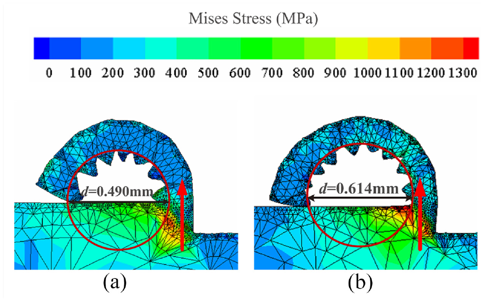
Cutting process of textured tool and diameter of chip curl (friction coefficient 0.9): (a) E = 200 μm, rake angle 0° and (b) E = 200 μm, rake angle 5°.
Conclusions
In this paper, the cutting lubrication process of textured tool is simulated by combining the R-SGFEM and the cutting simulation software AdvantEdge. Firstly, the friction coefficient, flow field pressure, and speed change of the lubricant are solved by R-SGFEM. Then, the cutting simulation is carried out by AdvantEdge. The following conclusions are obtained:
The simulation method of cutting lubrication is verified. On the basis of the friction experiment platform, the micro fluid pressure sensor is added, and the measured lubricating oil film pressure is taken as the boundary condition to slightly modify the simulation pressure. The error between the simulation and experimental results is within 10%, so the simulation method is reliable and effective.
Cutting force can be reduced by changing texture parameters and boundary slip length. The lubrication clearance and texture width are inversely proportional to the friction coefficient, while the texture spacing is positively proportional to the friction coefficient. A larger sliding length produces a stable and smaller cutting force in the y direction, and reduces the cutting temperature.
The cutting force can be effectively reduced by changing the rake angle of the tool and the length of the texture from the cutting edge. When the length of the texture from the cutting edge is different from the feed per revolution, the larger rake angle of the tool makes the diameter of chip curl larger. When the rake angle of the tool and the length of the texture from the cutting edge are smaller, the texture is easier to occur second cutting of chips.
In this paper, the cutting performance of textured tool has been studied and some results have been obtained. However, considering the thermal slip effect at the microfluidic boundary, it is of great significance to study the temperature change of textured tool under cooling conditions.
Footnotes
Handling Editor: Liyuan Sheng
Author contributions
Caiyun Duan: Methodology, Validation, Investigation, Resources, Writing – original draft. Yaoming Zhu: Methodology, Resources, Supervision, Writing – review & editing, Funding acquisition. Qinghua Song: Conceptualization, Supervision, Writing – review & editing, Funding acquisition.
Declaration of conflicting interests
The author(s) declared no potential conflicts of interest with respect to the research, authorship, and/or publication of this article.
Funding
The author(s) disclosed receipt of the following financial support for the research, authorship, and/or publication of this article: This work was supported by the Basic Research Projects of Yantai Science and Technology Innovation Development Plan (Grant No.2023YT06880519) and the Key Research and Development Plan of Shandong Province (Grant No. 202228125).