
Abstract
The transfer matrix method for multibody systems is a new method with very high computational speed developed in recent 20 years for studying multibody system dynamics. By combining transfer matrix method for multibody systems, computer graphics, and open-source software, this article puts forward an approach and software MSTMMSim for visualized simulation and design of mechanical system dynamics. The approach includes the following procedures in sequence: design of functional model, design of three-dimensional solid model, design of dynamics model, automated formation of dynamics equations, and software MSTMMSim for visualized simulation and design of mechanical system dynamics. The proposed method and software provide a platform to realize the simulation and design of complex mechanical systems with the following characteristics: (1) automatic deduction of the overall transfer equation, (2) high computational speed, and (3) high visualization and programming of dynamics simulation and design process. The proposed method and software are verified by the practical example of simulation and design of a tank system dynamics using this platform.
Keywords
Introduction
The dynamics design of mechanical systems has become the digital virtual pattern to promote properties and enhance reliability of systems, thus resulting in a shortened development cycle and less cost. 1 Various mechanical systems, such as vehicles, ships, aircrafts, spacecraft, modern weapon systems, numerically controlled machine tools, and robots, may be modeled as multibody systems comprising rigid and/or deformable bodies connected with hinges in various fashion.1–6 The software of multibody system dynamics, such as UG, Pro/E, CATIA, ADAMS, and ANSYS, has been widely used nowadays for the simulation and design of mechanical system dynamics. Now for almost all dynamics solvers of software based on ordinary multibody dynamics methods, there are two common characteristics. First, it is necessary to establish the global dynamics equation of system. Second, the system matrix is rather high for complex mechanical system, thus resulting in a heavy computation burden. Optimization of dynamics of complex mechanical systems will take long time if using these kinds of software. Consequently, there is an urgent demand for high speed of dynamics computation to realize the simulation and design of complex mechanical system dynamics.
The transfer matrix method for multibody systems (MSTMM) is a new method of multibody system dynamics with high computational speed developed in the past 20 years. It has been widely used in the analysis and design of complex multibody systems because of its following features: no need for global dynamics equations of system, very low order of system matrix, high computational speed and programming, and automatic deduction of the overall transfer equation.6–8 With the rapid development of computer graphics, various open-source software (OSS), such as Open CASCADE (OCC) and Coin3d, provides great convenience for developing simulation software of multibody system dynamics, especially the pre-processor and post-processor. In order to simulate and design the mechanical system dynamics efficiently, this article puts forward an approach and software MSTMMSim based on MSTMM for visualized simulation and design of mechanical system dynamics by combing computer graphics technology and OSS. The practical example of a tank system dynamics using the proposed method and software is shown in this article to verify the method and MSTMMSim. It lowers the demand for theoretical knowledge of technicians who use the simulation platform and provides a stylized pattern to simulate and design the dynamics of a mechanical system with high efficiency.
Structure of MSTMMSim
Basic structure of MSTMMSim
In this article, MSTMM is used as the core of solver for dynamics computation. Combining OSS including OCC and Qt,9,10 a new software for simulation and design of multibody system dynamics, named MSTMMSim similar to Yang et al., 11 is developed. It realizes the following functions: direct calling of various formats of three-dimensional (3D) model file, automatic generation of the dynamics parameters of a multibody system, visualized modeling, rapid computation, data processing, and animation displaying.
The basic structure of MSTMMSim is shown in Figure 1. The fundamental parts of MSTMMSim consist of three main modules: pre-processor, MSTMM solver, and post-processor. The graphical user interface (GUI) of MSTMMSim is developed primarily using C++ language and Qt framework. 10 The OCC geometric modeling kernel library is integrated into MSTMMSim. Users can import various types of computer-aided design (CAD) solid models built by other software. In MSTMMSim, the application program interface (API) of OCC can be called to achieve basic geometry modeling. Complex geometric model can also be established rapidly through the Boolean operations, that is, union, difference, and intersection. 9 The topology structure and parameters of a multibody system are automatically generated in MSTMMSim according to the connecting relations and material properties defined by the user. MSTMMSim solver reads the defined parameters, computes system dynamics, and stores the resulting data. Then, the results are returned to the user in any chosen form such as animations, curves, numerical values, pictures, and tabulations. The modules of MSTMMSim and their sub-modules are given in Table 1.

Basic structure of MSTMMSim.
Modules of MSTMMSim.

MSTMM: transfer matrix method for multibody systems; CAD: computer-aided design; MSD: multibody system dynamics; OCC: Open CASCADE.
Visualization of mechanical system dynamics
The visualization is a technique utilizing computer graphics and image processing to convert data into graph or image displayed on the screen, and to carry on interactive processing. The visualization of mechanical system dynamics includes the visualization of dynamics modeling, simulation process, and computational results, among which the visualization of the 3D solid models plays a significant role. The essence of visualization of the 3D solid is to transform discrete 3D solid data into discrete two-dimensional image data displayed on the screen in accordance with the rules of projection of a body.
Currently, various OSS, such as OCC and Coin3d, provides a convenient solution for the visualization of 3D solid. This makes it much easier for developers of software to realize the modeling, displaying, interactive processing, and storage of 3D solid even if the researchers have no specific knowledge on computer graphics. 9
Pre-processor module of MSTMMSim
The pre-processor module of MSTMMSim is developed using OCC geometric modeling kernel. The main function of the pre-processor is to set up the models of the mechanical system including functional model, 3D solid model, and dynamics model. Using pre-processor module, users can not only design the mechanical system but also import CAD files with standard format, such as IGES, STEP, and DWG/DXF, generated by other CAD software. As for homogeneous bodies, each body has a base coordinate system whose position and orientation with respect to the global coordinate system are used to represent the absolute position and orientation. The connection points can be defined by establishing the body-fixed coordinate systems on the body whose position and orientation are represented in the base coordinate system as shown in Figure 2. After the solid geometric figures of the mechanical system are generated, by setting the parameters of material properties, the dynamics parameters such as mass, position of mass center, and moment of inertia can be computed automatically and represented in the base coordinate system by calling the functions getMass(), getCenterOfMass(), and getMatrixOfInertia() in the GProp_Gprops base class of OCC. 9 These positions, orientations, and mass parameters are stored in an XML-based format file. The length, width, and height of the box shown in Figure 2 are 15, 10, and 10 mm. The base coordinate system is identified by position coordinates (0.01, 0.01, 0.005) of its origin with respect to the global coordinate system and is rotated by 15° about the Z-axis. The density of the body is set to be 7900 kg/m3. Then, the parameters stored in the XML-based file are formatted as follows:
<RigidBody Name = “Box” ID = “1” Label = “Box”>
<AbsolutePosition>0.01, 0.01, 0.005</AbsolutePosition>
<AbsoluteOrientation>0, 0, 0.2617994</AbsoluteOrientation>
<Marker ID = “1”>
<Position>0, 0, 0</Position>
<Orientation>0, 0, 0</Orientation>
……
</Marker>
<Marker ID = “2”>
<Position>0.015, 0.01, 0.01</Position>
<Orientation>0, 0, 0</Orientation>
……
</Marker>
<MassCenter>
<Position>0.0075, 0.005, 0.005</Position>
<Orientation>0, 0, 0</Orientation>
……
</MassCenter>
<Density>7900</Density>
<Mass>0.01185</Mass>
<JI>7.9e−07, 1.28375e−06, 1.28375e−06, −4.44375e−07, −4.44375e−07, −2.9625e−07</JI>
……
</RigidBody>

Definition of connection point.
As for the inhomogeneous bodies, as well as beams and shells, the finite element scheme is utilized where each finite element is regarded as homogeneity. The parameters of the body are first specified in each element, and then the strategies of finite element method are used to obtain the dynamics parameters of the whole component. The parameters are stored in the format of ABAQUS inp document. Figures 3 and 4 show the finite element model of a beam and connection points on it, respectively. After the parameters of the bodies are set, they are saved in the XML document and the inp document, which will be invoked and computed by the solver.

Finite element model of the beam.

Connection point on the beam.
MSTMM solver module of MSTMMSim
MSTMM solver module is developed based on MSTMM using C++ language, where the transfer equations and transfer matrices of each element are generated automatically based on the corresponding dynamics model and its topology figure by calling the transfer matrix library.6–8 The overall transfer equation and overall transfer matrix of the system are generated automatically by following the automatic deduction theorem of overall transfer equation of multibody system.
7
Furthermore, the computation of system dynamics can be implemented using the algorithm of MSTMM.
8
The automatic deduction theorem of overall transfer equation is based on tree systems. As for multibody systems which contain closed loops, the technique of auto selecting the cut hinges is established by introducing the correlation matrix and the dynamic connectivity matrix that depict the connecting state of elements. For a multibody system containing

where the first line denotes the sequence number of hinges, and the second and third lines indicate the sequence numbers of bodies connected to the hinge listed in the first line. If a hinge is directly linked to a boundary, the corresponding number in second or third line will be “0.” The matrix

For example, if
Set
Set
The system will be augmented by adding hinge
If
Terminate if
It should be noted that in MSTMM, boundaries will not cause closed loops, so if
Herein, object-oriented programming method is used to build the base class of the element, where the body element class and the hinge element class are derived. Furthermore, element objects are defined using these element classes. The data structure of a tree system stored in a computer is shown in Figure 5, where the “ID” represents the sequence number of the element; the “input” (or “output”) represents the sequence number of an element or boundary connected to its input end (or output end); the “data” stores all the parameters of the element; and the “TM” denotes the transfer matrix of the element. According to the definition of the topology of the dynamics model of a multibody system in the context of MSTMM, it can be found that
Each element has only one “output” and multiple “inputs”;
The element whose “output” equals to zero is the root of the system, and the connection point on the element corresponding to “output” is the output end of the system;
The connection point on the element corresponding to “input = 0” is the input end of the system.

Data structure of a tree system.
The automatic deduction of the overall transfer equation of a multibody system has already been studied in Rui et al. 7 The realization of such automatism in a computer lies in finding the transfer paths from tip elements to root element, and to bifurcated elements. Herein, we illustrate such process according to Figure 5 as follows. Starting from the element whose “input = 0” (the input end of the system), one can search the “output” of the element and consequently find out its adjacent element connected to its output end. The above procedure can be repeated until the element whose “output = 0,” indicating the output end of the system is reached. The sub-matrix of the main transfer equation 7 corresponding to the input end of the system can be obtained by multiplying the transfer matrix of the elements in the search path. Analogously, starting from the element whose “input = 0,” one can search its adjacent element connected to its output end. This procedure can be repeated until the element with multiple input ends is found. Then, the sub-matrix of the geometric equation can be obtained by multiplying the transfer matrix of the elements in the search path and pre-multiplying the geometric coefficient matrix. By adding the sub-matrices of the main transfer equation and the geometric equation to the block in the overall transfer matrix corresponding to the boundary state vector, the overall transfer matrix of the system can be obtained, and the automatic deduction of the overall transfer equation is realized in the computer.
Post-processor module of MSTMMSim
The post-processor module is developed using OCC, Qt, and Qwt, where the computational result datum from MSTMM solver is stored for each interested body, including their positions, velocities, accelerations, angles, angular velocities, angular accelerations, internal torques, and internal forces. The data outputs are achieved by means of animations, curves, numerical values, pictures, and tabulations.
Basic principle and steps of simulation and design of MSTMM
Basic principle of simulation and design of mechanical system dynamics
The design of mechanical system dynamics is an iterative process starting from a functional model of the mechanical system. It repeatedly predicts, evaluates the current overall design scheme, and compares with the previous one to acquire a design scheme that better satisfies the performance requirement of a mechanical system. It includes the following procedures in sequence: design of functional model, design of 3D solid model, design of dynamics model, design of the mathematic model, simulation and optimization of the multibody system dynamics, virtual test, formation of the scheme, and experimental verification. By comparing with the experimental results, the final design scheme can be formed if it satisfies the performance requirement; otherwise, the design parameters will be repeatedly optimized until the requirement is satisfied. Figure 6 shows the flow chart of the overall design process of a mechanical system dynamics. The proposed method in this article has been applied to the dynamics designs of many practical complex mechanical systems.

Flow chart of the overall design process of mechanical system dynamics.
Functional model design of a mechanical system
The design of the functional model is to figure out the shape and dimensions of major parts or subsystems that have relative motion among a mechanical system. The functional model of mechanical system is generated through the 3D modeling module embedded in MSTMMSim. This process is mainly based on a designer’s imagination or existing drawings. Upon designing a mechanical system, the designer will first identify the basic function of the system according to practical requirement or specifications, which provides basic dimensions for the follow-up detailed 3D solid models. As shown in Figure 7, the functional model of a tank is designed using MSTMMSim. The tank should have the function including marching, turning around, firing, and adjusting of the pitch and yaw angles. According to these functional requirements, designer designs the approximate shape and dimension of the tank, the number of road wheels, and figures out the shape of the caterpillar band, turret, elevating part, recoil part, and so forth.

Functional model of tank.
3D solid model design of a mechanical system
The design of the 3D solid model is to precisely depict the 3D entity of a mechanical system and to design the physical structural parameters for dynamics computation such as the mass, moment of inertia, and position of mass center based on its functional model. The 3D solid model can be built directly by the 3D modeling module embedded in MSTMMSim or imported from other commercial 3D modeling software such as UG and Pro/E. In MSTMMSim, the 3D solid model of a mechanical system can be generated by calling the modeling module of OCC and displayed by the OCC Viewer module, where the parametric modeling technique is utilized. Figure 8 shows the 3D solid model of the tank established using MSTMMSim according to its functional model. Via human–computer interaction, the assembling relations of recoil part and elevating part, elevating part and revolving part, revolving part and hull, hull and suspension, caterpillar bands and road wheels, and caterpillar bands and the ground are defined.

3D solid model of tank.
Dynamics model design and topology figure of a mechanical system
The design of the dynamics model is to establish the dynamics model and its topology figure of multibody system automatically according to the 3D solid model of a mechanical system. By defining the coordinates of connection points of body elements and calling the defined hinge elements from the transfer matrix library, the dynamics model will be automatically generated via the 3D solid model. By exporting the data of the multibody system in the form of Graphviz dot language and calling the Graphviz software, the topology figure of multibody system will be automatically generated according to the symbol conventions of MSTMM and automatic deduction theorem of overall transfer equation of multibody system. 7 A multibody system is composed of bodies and hinges, where bodies include lumped masses, rigid bodies, elastic bodies, and so forth, while hinges indicate the general relationship of position, rotation angle, velocity, angular velocity, acceleration, angular acceleration, internal forces, and torques between two bodies. Typical hinges include smooth ball-and-socket hinges, pin hinge, translational hinges, elastic hinges, and dampers.6–8
Dynamics model of the multibody system and its topology figure of the tank are automatically generated, as shown in Figures 9 and 10, respectively. The topology figure describes the transfer relationship among the state vectors of adjacent elements and the transfer directions in a system, where a circle “o” denotes a body element and an arrow “→” denotes a hinge element and the transfer direction of state vectors. The bodies and hinges are numbered uniformly. In Figure 10, the recoil part of the tank (containing gun barrel, gun breech, muzzle brake, etc.) is numbered 1, the gun cradle is numbered 3, the turret is numbered 5, the tank hull is numbered 7, the balance elbows are numbered 32–37 and 38–43, the drive sprockets are numbered 56 and 68, the road wheels are numbered 57–62 and 69–74, the support wheels are numbered 63–66 and 75–78, while the idlers are numbered 67 and 79. There are totally 164 creeper treads with 82 creeper treads lying on each side, respectively. The creeper treads on the right side of the tank in its forward motion are numbered 80, 82, 84, …, 242, respectively, while the left 244, 246, 248, …, 406. The track link pins are considered as hinges. The hinges corresponding to the track link pins on the right side of the tank are numbered 81, 83, 85, …, 243, respectively, while the left 245, 247, 249, …, 407. Through human–computer interaction, the dynamics properties of each element in the tank can be set. The mass, moment of inertia, position of mass center, and so on, can be automatically generated by the MSTMMSim. Meanwhile, users should also set the dynamics parameters of each hinge element including stiffness and damping. Furthermore, the connection parameters of caterpillar band and road wheels, and caterpillar band and the ground, should also be set.

Dynamics model of tank.

Topology figure of tank dynamics model.
Basic idea of MSTMM
The basic idea of MSTMM is to decompose a multibody system into elements containing bodies and hinges whose dynamics properties can be readily expressed in matrix form. These matrices of elements are considered as building blocks that provide the dynamics properties of the entire system when assembling them together according to the topology of the dynamics model of multibody system. Especially, bodies and hinges are considered the equivalent position in transfer equations and transfer matrices.
For a chain multibody system undergoing spatial motion, the state vector of a connection point between any two elements is defined as

where
For an element numbered j, it can be proved that its transfer equation keeps the form 8

where
According to kinematics and Newton’s third law, and the specific sign conventions,
7
the state vectors of element j’s output end coincide with that of k’s input end, where k is the outboard element of j. This allows to substitute input states


where
Seen from equation (6), for a chain system, the overall transfer matrix equals to the successive multiplication of transfer matrices of elements in the transfer path from the tip to root. The order of system matrix in MSTMM is very low and equals to the order of transfer matrix of a rigid body, thus resulting in very high computational speed. Comparisons on computational precision and speed of MSTMM with other dynamics methods can be found in Rui et al.6–8
Automated formation of dynamics equations
Seen from equations (5) and (6), the overall transfer equation can be deduced automatically. The state vectors involved in an overall transfer equation are the column matrix comprising the state vectors of all boundary ends of the system. The overall transfer matrix
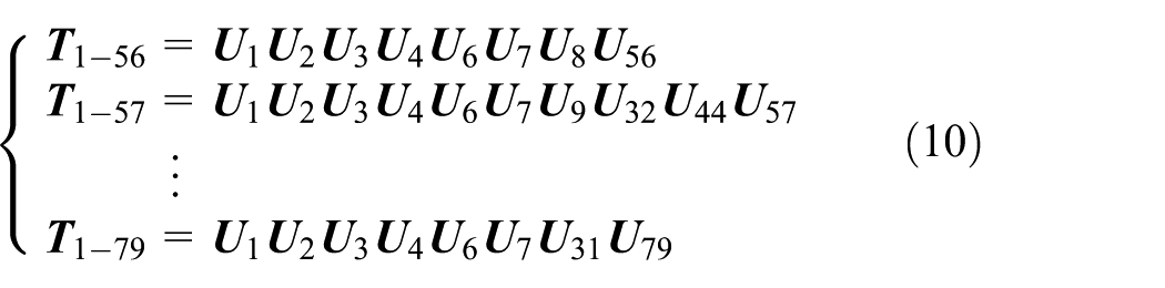
The transfer equation and transfer matrix of the tank element will be formed automatically by calling the transfer matrix library installed in the MSTMMSim shown in Rui et al.6–8 The overall transfer equation of the tank like equation (7) will be formed automatically using automatic deduction theorem of overall transfer equation of multibody system 7 as follows

where


Simulation and optimization
The MSTMMSim will call the MSTMM solver to compute and optimize the tank system dynamics. An unconstrained optimization problem for tank multibody system dynamics is set up as follows: the root mean square (RMS) value of the vertical acceleration of the mass center of hull is selected as objective function f(x), while the damping coefficient of the torsional stabilizer is chosen as a single design variable x with bounds [0, 3 × 10⁴] N·m/rad. The Brent’s optimization method which combines the reliability of the golden-section search with the speed of parabolic interpolation is adopted. As shown in Figure 11, the minimum of the objective function f(x) is found with 25 iterations, where the optimal value of damping coefficient of the torsional stabilizer is 4344 N·m/rad.

Interface of animation display of simulation of tank dynamics.
Under the above optimal scheme, Figure 12 shows the visualized interface of the tank system dynamics during marching, and Figure 13 shows the interface of the time history of velocity and acceleration of the mass center of the hull of the tank, respectively.

Interface of animation display of simulation of the tank dynamics.

Interface of simulation results of velocity and acceleration of the tank in the vertical direction: (a) velocity and (b) acceleration.
Furthermore, we consider a typical system to demonstrate the computational speed of the proposed method and the software. A planar pendulum system is formed by N (

Comparison on time cost by the new version of MSTMM and Lagrange method.
Conclusion
Concentrating on the speedy simulation of multibody system dynamics, and by combing computer graphics technology and OSS, this article puts forward the new method and software MSTMMSim for visualized simulation and design of mechanical system dynamics based on MSTMM. A tank and a pendulum system are taken as two practical examples to verify that the simulation and design of complex mechanical system dynamics own the following features if using MSTMMSim: very high computational speed, and very high visualization and programming. It provides powerful tool for the simulation and design of complex mechanical system dynamics.
Footnotes
Acknowledgements
The authors own special thanks to Prof. Dieter Bestle from Brandenburgische Technische Universität, Cottbus, Germany, who offered important suggestions for this paper in his academic visit to Nanjing University of Science and Technology.
Academic Editor: Chuanzeng Zhang
Declaration of conflicting interests
The author(s) declared no potential conflicts of interest with respect to the research, authorship, and/or publication of this article.
Funding
The author(s) disclosed receipt of the following financial support for the research, authorship, and/or publication of this article: This research was supported by the Research Fund for the Doctoral Program of High Education of China (no. 20133219110037) and the Basic Project for Defense Base of China (no. JCKY 2013620133008).