
Abstract
The steel plate straightening quality has an important influence on the welding quality and service performance of excavator’s boom and arm. In this study, a stress neutral layer offset model was established based on three-point bending theory, steel plate bending characteristics, and layered theory in the straightening process. The stress neutral layer offset phenomenon and the relationship among the reverse bending radius, the plate thickness, and the metal deformation capacity have been proved theoretically. Combined with the tensile and bending tests at room temperature, the relationship between the neutral layer offset values and the reverse bending radius was obtained, and the results showed that the stress neutral layer offset value increases with the decrease in the reverse bending radius. The neutral layer offset phenomenon was also verified by the straightening experiment, and the flatness of the straightened high-strength steel plates is less than 1 mm/m.
With the formulation and development of Chinese One Road, One Belt strategy, the transportation, hospitals, education construction, and other infrastructures are getting into a rapid development stage, which provides many great development opportunities to the construction machinery industry, one of the pillar industries for the national economy. Excavator is a main part of engineering machinery equipments,1,2 which consists of a power plant, transmission device, walking device, and working device. The boom and arm are two important parts and force components of the working device, and they are also the connecting components of the rotary platform and the digging mechanism. Their main function is to support the digging action of scraper bucket, and lifting and unloading of material repeatedly.3,4 The manufacturing and welding quality of boom and arm directly affect the whole performance, reliability, and cost of the excavator. 5 With the development of a hydraulic servo adaptive control technology, the working devices are beginning to turn to automation and intelligent. The use of adaptive robust control for the hydraulic servo system realizes a high-precision control of the working device action,6–8 reduces the shock, vibration, and noise caused by the velocity mismatch of each joint, and extends the service life of the working device. However, the damage of boom and arm also occurs frequently, especially in the severe environments, such as the plateau or frigid zone. In these cases, their shock and vibration are still very large, the load change frequency is also high, and crack will appear. 9 The damage of the boom and arm was analyzed in the previous studies by Danicic et al. 10 and Bosnjak et al., 11 which found that the main causes of the crack initiation are the low strength and welding defects of the steel plate (in Figure 1). Thus, the boom and arm are generally welded by the high-strength steels. 12 The flatness of high-strength steel is also a main cause of welding defects, because it is difficult to be straightened.13,14 So, it is of both fundamental and practical importance to study the high-strength steel plate with high accurate flatness.
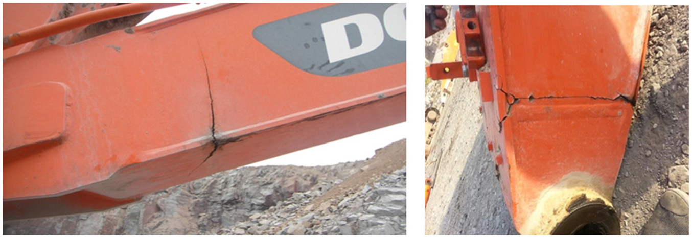
Defect diagram of excavator’s boom and arm.
Multi-roll straightening is a straightening process of continuous bending and mainly used in plate production line, whose main function is to eliminate the buckling and wave defects of rolling and cooling process, guarantee the flatness of flat plate, and eliminate residual stress.15,16 Multi-roll straightening machine has the characteristics of high production efficiency and easy realizing mechanization with a wide range of application. The key factor to determine the quality of the high-strength sheet is the setting of the process parameters.17,18 The process parameter calculations have ignored the neutral layer offset in the traditional straightening theory, which generally leads to greater errors in the process parameter setting. According to Guan et al.’s 19 research, under a certain relative radius, the relative error of springback, with considering the neutral layer offset, can reach up to 70% and above, because the neutral layer offset can change the stress distribution of the steel plate, and affect the calculation of the bending moment ratio and bending rate. The neutral layer offset also helps to reduce the elastic core and improve the unstable straightening quality caused by the residual stress recovery. In this work, a mathematical model of neutral layer offset was developed based on the three-point bending, the layered theory, and elastic–plastic theory. A field experiment was conducted, which was analyzed using the theoretical model of neutral layer offset. The results show that the migration value of neutral layer increases with the increase in the bending degree. Our study can provide new insight into the straightening mechanism of high-strength steel plate and welding defect control of excavator’s working arm.
Establishing theoretical model
Basic assumption
The cross-section of the plate is kept as the plane and is perpendicular to the central axis of the plate after the deformation.
Material is continuous, homogeneous, and isotropic, and the strain neutral layer is considered to coincide with the stress neutral layer.
The variation of the width of the steel plate is ignored during the straightening process.
The tensile and compression deformation hardening features are the same, which means their stress and strain relationship is consistent.
Tensile and compressive test of metal is a uniaxial tension and compression state, where plastic deformation meets the linear hardening model: σ = σt + λE(εp − εt), where λ is the linear hardening coefficient, E is the elastic modulus, σt is the yield strength, and εt is the elastic limit strain.
Layered theory of metal
Finite element method is the basis of layered theory, which has been applied to the stress analysis of the plate in the straightening process. The analysis procedure is as follows: the unit length plate is taken from the contact area of the middle straightening roller in the straightening group and divided into n layers along the central axis plane a-a. The law of each layer element is the same, thus, it is only necessary to analyze the stress of the layered element. The layered element will be used to deal with many necessary mathematical or physical problems,20,21 as shown in Figure 2.
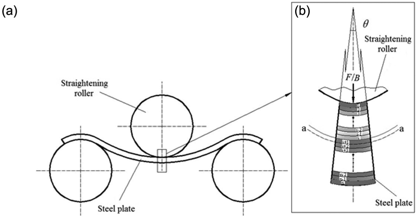
Hierarchical diagram of unit length plate: (a) diagram of three-point bending and (b) local enlarged drawing.
Geometric strain analysis
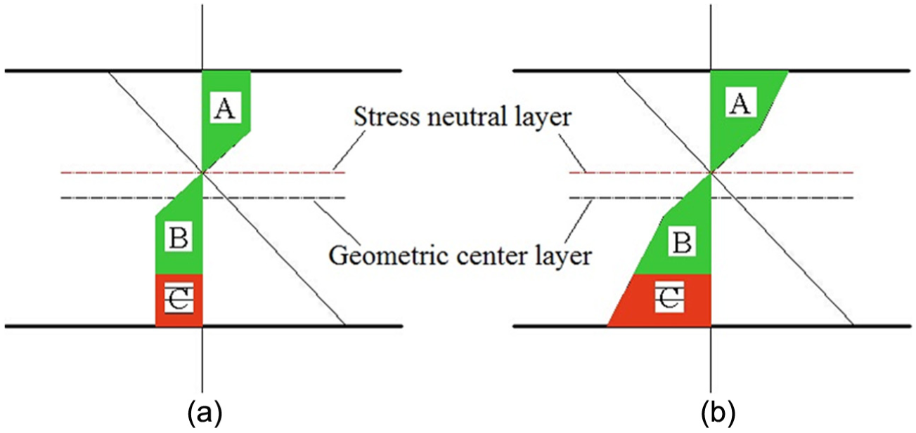
Before entering a multi-roll straightening machine, plates have many kinds of original bending types in the length direction, and their bending degrees are different, but all of them will be unified into a single bending type in the large deforming process. Generally, the original bending type is simplified as single bending state to facilitate the theoretical analysis.22,23 It can be assumed that the layered element is initially in tensile state and then in compression state after reverse bending, as shown in Figure 3. Because the original bending of the plate is not significant, it can be considered as that the neutral layer is coincident with the geometric central axis,24,25 and the original length of neutral layer of the plate is

where

where

where

where r is the radius of the layer element.

Straightening deformation diagram of unit length plate: (a) diagram of initial bending and (b) diagram of reverse bending.
Therefore, the true strain of the layered element in the tangent direction

The length of the neutral layer of the plate is constant

Finally

Plastic εt–5εt fitting relationship
Multi-roll straightening process of steel plates is a complicated elastic and plastic deformation of repeated bending, and the stress superposition effect should have been taken into account. But Liu’s 26 research indicates the reverse bending rate with considering stress superposition effect, and the reverse bending rate without considering stress superposition effect is very close, so the stress superposition effect is ignored in this work. In the analysis of springback theory, it is necessary to carry out the integral calculation of the stress distribution of the steel plate in cross-section. Compared to the exponential hardening model which can describe the constitutive relationship of material accurately, the bilinear hardening model has the advantages of being simple and easy to integrate, and the accuracy can be guaranteed. So, the bilinear hardening model was used to describe the stress and strain relationship of the straightening deformation. The data of the yield strength to extension were used in the traditional bilinear fitting, but the fitting accuracy was poor for the material which has the yield platform, as shown in Figure 4. In the actual production procedure, when the plastic deformation of the bending strip reaches a depth of 80% in whole section, if no crack appears, any metal strip can be leveled. 27 Therefore, the maximum strain of the general specification for plate straightening was defined as 5εt, and εt is the elastic limit strain. The data of plastic deformation, from εt to 5εt, were fitted by a straight line, and its slope is the hardening modulus E′. Therefore, the hardening coefficient in plastic deformation is given by

where E′ is the hardening modulus, E is the elastic modulus, and

Simplified models of stress–strain on different ductile materials: (a) material with yield platform, (b) material with short yield platform, and (c) material without yield platform.
Neutral layer migration model
One side of the plate in contact with the straightening roller is subjected to compressive stress, and the other side of the plate is subjected to tensile stress in the straightening process, as shown in Figure 5.
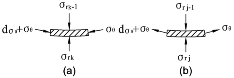
Stress diagram of layer unit: (a) diagram of unit stress in compression zone and (b) diagram of unit stress in tensile zone.
A differential equation on the layer unit in the θ direction is as follows

where h is the plate thickness, σθ is the stress in the θ direction, n is the number of layers, and
Assuming that the neutral layer is shifted between i and i + 1, the equation is established for j number of layer unit in the r direction
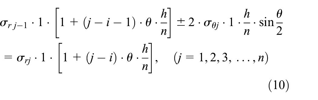
where the stress analysis of the tensile zone is taken as “+,” and the compression zone is taken as “−”; θ is the bending angle; and σr is the stress in the r direction.
The equations of each layer unit are superimposed

Because the unit length of the plate is the study object, it can be considered that

It can be found that the stress distribution in the cross-section of the plate is used to balance the stress in the r direction caused by the external force. Therefore, it can also prove that the stress neutral layer must be shifted in the bending process. As a result, the above equation is simplified to

where e is the offset value of the stress neutral layer, and Rw is the bending radius of the plate.
The relationship between the pressure and the stress of the plate surface in the r direction is as follows

where F is the pressure exerted by the roller, E* is the equivalent elastic modulus, B is the width of plate, and R is radius of the straightening roller
The calculation method of

Stress distribution diagram of plate section: (a) material without hardening phenomenon and (b) material with hardening phenomenon.
The influence of the deformation on stress between the straightening roller and the plate is very complicated in the straightening process, so a correction coefficient is used. When the plate is an ideal elastic–plastic material, the stress neutral layer migration model is as follows

where η is the correction coefficient, which is associated with the material properties and the bending, and determined by a large number of simulations and experiments.
It is assumed that the plate is a hardening elastic–plastic material, as shown in Figure 6(b)
where

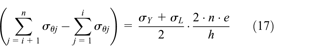
When the plate is a bilinear elastic–plastic material, the stress neutral layer migration model is as follows

where σY is the stress of the outmost unit in the compression zone of plate; Rw is the bending radius of plate; σL is the stress of the outmost unit in the tensile zone of steel plate.
Experimental verification
Room temperature tensile test
Tensile testing is the most basic test of the mechanical properties of the materials. The yield strength, elongation, and tensile strength of the material are obtained, and they are the main factors affecting the bending deformation. Q690 steel was in the tensile test, and the experimental results were analyzed to provide the parameters for the model establishment.
Tensile experiments were carried out on WAW1000. The mechanical property of the plate is shown in Table 1, and its stress–strain curve is similar to that in Figure 4(c).
Mechanical property of materials.

Bending test
Bending test is one of the basic methods for determining the mechanical properties of the materials when subjected to bending load. The two ends of the plate are supported by fulcrums, and a concentrated load using a hydraulic pressure testing machine of 100 kN is applied in the middle of the plate. The hydraulic pressure testing machine is controlled by the electro-hydraulic servo system, and the load and displacement change curves can be displayed by the electro-hydraulic servo test system.
Pretreatment of bending specimen
First, the sheet was cut into a standard size of 20 × 40 × 400 mm3 (thickness × width × length), and it must be ensured that the cutting surface was perpendicular to the upper and lower surfaces of the steel plate in the cutting process. The Dove licensing sandpaper was used to make the cutting surfaces of strip specimen smooth. The cutting surface was divided into uniform grid by a stylus, and the grid is similar to the finite element method, as shown in Figure 7.

Deformation diagram of plate sectional grid before bending (sample no. 5).
Experimental process
The strip specimen was placed on the fulcrum of the pressure testing machine, and the press head of the pressure testing machine must be ensured in the middle of the sample. 28 Then, the reduction was set according to the previous test requirement. The specific test scheme is shown in Table 2.
Experimental data record table.

Post-processing of bending specimen
According to the method shown in Figure 8, Nikon S4150 camera was used to image the cutting surface of bending specimen. The photo was imported into the computer-aided design (CAD) software and amplified to the corresponding multiple to measure the exact size. The cutting surface grid of the bending specimen is shown in Figure 9.
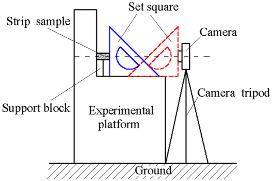
Photo sketch.

Deformation diagram of plate sectional grid after bending (sample no. 5).
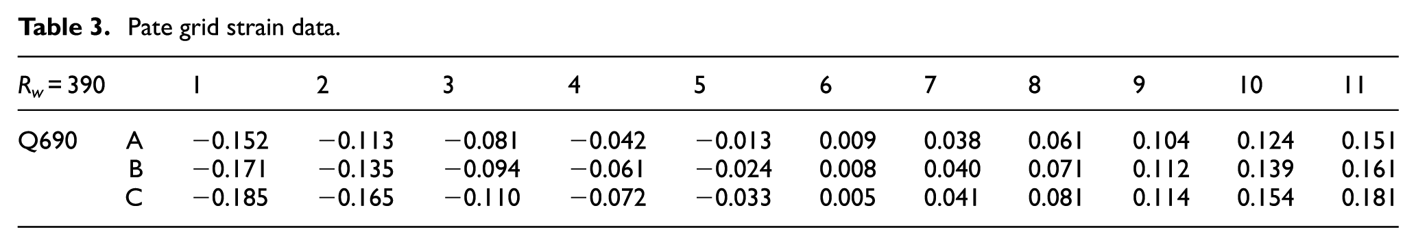
The hash grid that is nearest to the press head was used to analyze strain. Due to the plane strain hypothesis and the bending deformation of plate is mainly longitudinal fiber, the longitudinal strain state of the grid was only analyzed, as shown in Figure 9. Three column grids, A, B, and C, were selected to be repainted in CAD. The grid shapes before and after deformation were compared, and also the longitudinal grid line length of the three-column grid before and after bending. Then, the ratio of the length of the grid line was taken as the natural logarithm, and the value was used as the longitudinal strain of the plate. Assuming that the tensile strain of the plate is positive and the compression strain is negative, the linear strain data of the three-column grid are shown in Table 3.
Pate grid strain data.
According to the position distribution of the grid line in the diameter direction, from the lower edge to the upper edge of the plate, the position strain curves were drawn in the diameter direction, as shown in Figure 10.
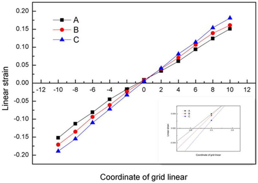
Board section line strain relations (sample no. 5).
Figure 10 shows the strain distribution on Q690 steel in the diameter direction, and the coordinate of the original neutral layer is zero (the geometrical neutral layer and the strain neutral layer are coincident before loading). It can be seen from the partial enlarged drawing that the original strain neutral layer is positive strain, which suggests that the metal was stretched. The lower edge strain of the plate is negative. According to the principle of deformation continuity, it can be found that a fiber layer with zero strain must exist between the position of original neutral layer and the lower edge of the steel plate. This fiber layer is the position of the strain neutral layer after bending. It can be shown from the figure that the strain neutral layer will be shifted to the compression side in the bending process. The migration value of the strain neutral layer of the three-column grid, respectively, is 0.687, 0.437, and 0.267 mm. The experimental values of the strain neutral layer offset on steel plates (sample nos 1–6) in the reverse bending radius are shown in Table 4.
Experimental data of neutral layer offset under different reverse bending radii.

Result analysis
Relationship between the neutral layer offset and the reverse bending radius
The reduction change in the three-point bending is achieved by the external force F. Therefore, the reverse bending radius Rw is associated with the external force F. Q690 steel, whose initial bending radius R0 = 25,010 mm, was used to explain the relevant changes and trends, and the change in the neutral layer offset and the reverse bending radius is shown in Figure 11.

Curves of neutral layer offset and bending radius.
It can be seen from Figure 11 that the value of the neutral layer on Q690 steel increases with the decrease in the reverse bending radius and the result is similar to the literatures;29,30 the smaller the reverse bending radius, the smaller the error between the theoretical value and the experimental result. When the reverse bending radius Rw = 1130 mm, the error between the theoretical value and the experimental result is larger, and the main reason is that the larger the reverse bending radius, the smaller the migration value of the neutral layer. In addition, the test method, measurement process, and the existed error of correction coefficient were taken into consideration for the percentage of the error and the theoretical value of the neutral layer. When the reverse bending radius is smaller, the difference between the theoretical and the experimental values is less than 0.5 mm, and they follow the same trend. Therefore, it can be considered that the calculation data of the equation (18) are acceptable.
Straightening experimental analysis
The high-strength steel plate (Q690) was straightened in this experiment. The straightening machine and the data acquisition system are shown in Figure 12. The five pieces of straightening steel plates, whose specification was 6 × 600 × 1300 mm3 (thickness × width × length), were randomly selected to measure the flatness. After comparison, it was found that due to the effects of environment, process parameters, and other factors, one steel plate could not be straightened, and the straightness of the failed steel plate was 1.57 mm/m, which is more than 1 mm/m. Four pieces of steel plates were qualified and their straightness could meet the standard of less than 1 mm/m, as shown in Figure 13. First, the stress neutral layer offset affects the stress distribution of the straightened plate’s cross-section. It is all known that the straightening quality is guaranteed by precise reverse bending and springback, and the reverse bending and springback calculations are affected by the stress distribution of the plate’s cross-section. Thus, the stress neutral layer offset has impact on the reverse bending and springback calculations, and finally affects the straightening quality. In addition, three steel plates without considering the neutral layer migration were also tested to make comparisons. The results show that their straightness could not meet the standard of less than 1 mm/m, as shown in Table 5.
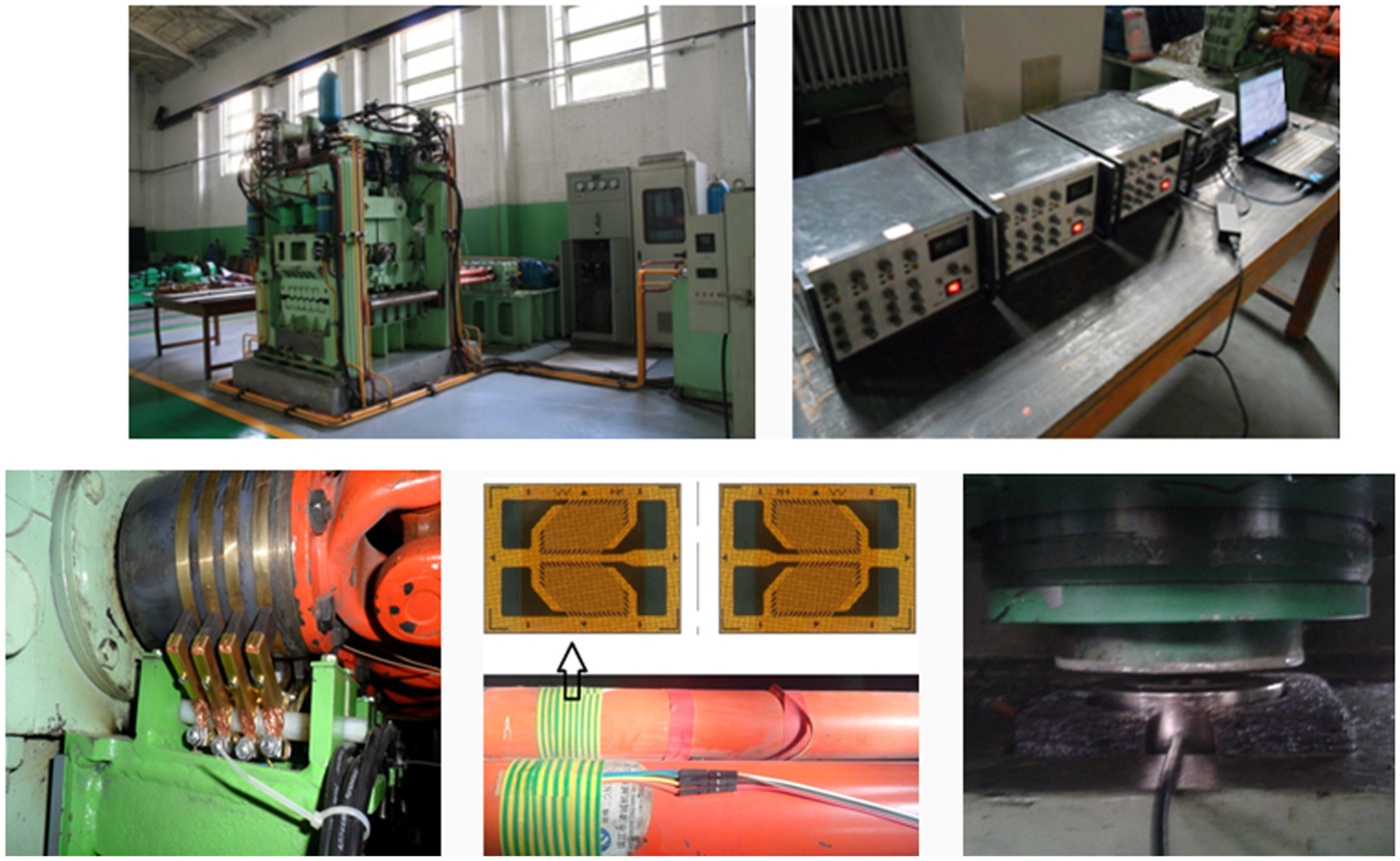
Eleven-roller straightening machine and data acquisition system.

Shape diagram of steel plate.
Test data on straightening quality of two groups’ plates.

Therefore, the applicability and reliability of the developed theory have been proved by the straightening practice.
Conclusion
The established neutral layer offset model can be used to estimate and analyze the neutral layer position of the high-strength steel plate in the bending process. The experimental results show that the model is acceptable and can provide a theoretical reference for the further study on the straightening mechanism of the high-strength steel plate.
After the neutral layer offset model of straightening steel plate was analyzed, it was found that the migration value of the neutral layer is related not only to the reverse bending radius, the mechanical properties, and the specification of the steel plate but also the initial bending radius and the external force.
When the steel plate is straightened, the migration value of the neutral layer increases with the decrease in the bending radius.
Footnotes
Academic Editor: Filippo Berto
Declaration of conflicting interests
The author(s) declared no potential conflicts of interest with respect to the research, authorship, and/or publication of this article.
Funding
The author(s) disclosed receipt of the following financial support for the research, authorship, and/or publication of this article: This study was supported by the Key Research and Development Program of Shanxi Province (201603D121010), the Science and Technology Project of Jincheng City (20155010), and NSFC—the Coal Base and Low Carbon Joint Fund of Shanxi Province (U1510131).