
Abstract
The motion control accuracy of the excavator manipulator is the primary guarantee for autonomous excavators to complete work tasks. This paper studies the motion control strategy of the manipulator of a certain autonomous excavator. By establishing a dynamic model of a 3-degree of freedom of excavator manipulator, the gravity term, inertia term, and centripetal force term in the model are equivalent to external disturbances for online compensation, which improves the motion control accuracy of the excavator manipulator. Based on the dynamic model, a control method of the bucket tooth tip trajectory of an autonomous excavator is proposed. The simulation and test results show that the maximum tracking errors of the joint angles of the boom, the bucket, and the bucket are reduced by 43.14, 26.56, and 51.05% respectively, and the average errors of the whole trajectory are reduced by 56.41, 61.33, and 64.26% respectively. The simulation and test results show that the proposed motion control strategy improves the operation accuracy of the excavator, and can effectively improve the operation accuracy and efficiency of the autonomous excavator.
Introduction
With the progress of science and technology, Excavators have evolved from simple mechanical hydraulics to a high level of automation and intelligence. The development of unmanned hydraulic excavators is obviously on the rise.1–3 Curve excavation, straight line excavation, slope excavation, gully slope excavation, and sand and gravel stacking are all extremely repetitive excavation operations carried out by autonomous excavators. The sophisticated nonlinear hydraulic actuator is one of the most difficult aspects of its motion planning and control.4,5 The control accuracy and working efficiency of the autonomous excavator are jointly determined by the accuracy of the boom hydraulic actuator, the arm hydraulic actuator, the bucket hydraulic actuator, and the rotary hydraulic motor.6–8 The task determines the work content of the autonomous excavator, and organizes the route planning according to the relevant work objectives. Controlling the hydraulic cylinder through the known planned path results in the telescopic stroke that satisfies the kinematics theory of the excavator manipulator.9–11
At present, many scholars have studied the control strategy of excavator manipulators.12–16 In order to realize coordinated control of autonomous excavators, Wang et al. 17 employed the cross-coupling pre-compensation (CCP) method to integrate its compensation with the nonlinear proportional integral controller of each actuator. Lee et al. 18 introduced a contour control algorithm for the leveling operation of the excavator, which improved the leveling accuracy of the excavator. Chang et al. 19 employed a robust control technique to compensate for the nonlinear hydraulic actuator of the excavator manipulator. Hanh et al. 20 created a simplified excavator arm trajectory controller with two degrees of freedom using a fuzzy neural network self-tuning technique. Feng et al. 21 developed an improved genetic algorithm (IGA) to optimize the parameters of the excavator PID controller and obtained an IGA-tuned PID controller. Lee et al. 22 employed data-driven model inversion to execute the offline training model in a supervised way, and used model inversion control to make nonlinear compensation for DX380LC, which substantially improved the tracking accuracy of hydraulic actuators.
The majority of existing research results focus on optimizing the controller design to increase the tracking precision of the excavator manipulator’s hydraulic cylinder.23,24 The control approach they use is to directly adopt the estimated point as the center of gravity of the manipulator, and it is often impossible to precisely determine the actual center of gravity of the manipulator after the bucket of the excavator is loaded. 25 In the field of excavator automation, there are few studies on online identification of excavator mechanical parameters and compensation control of external disturbance compensation of hydraulic cylinders. In this paper, the gravity, centripetal force, and inertial force of the manipulator are online compensated by online identification of the position parameters of the manipulator’s center of gravity, which effectively eliminates the influence of external interference during manipulator movement and improves the autonomous excavator’s operation accuracy and efficiency. Through the kinematics and dynamics simulation and test of the excavator, the autonomous operation of the excavator is realized. Through the gravity compensation strategy, the influence of gravity is eliminated as much as possible. The inertial force term, centripetal force term, and Coriolis force term generated by the movement of the excavator working device are modeled correspondingly, which increases the accuracy and efficiency of the excavator’s autonomous operation. It provides support for the independent operation of excavators in subsequent engineering practice.
Establishment of the online dynamic equation of manipulator
In this section, the manipulator of the autonomous excavator has 3 degrees of freedom. The dynamic model is established as shown in Figure 1. The model mainly includes a boom, arm, bucket device, and its corresponding hydraulic cylinder. Simplify the masses of the boom, arm, and bucket to the centroid of the manipulator, and then the Jacobian matrix of manipulator is calculated.
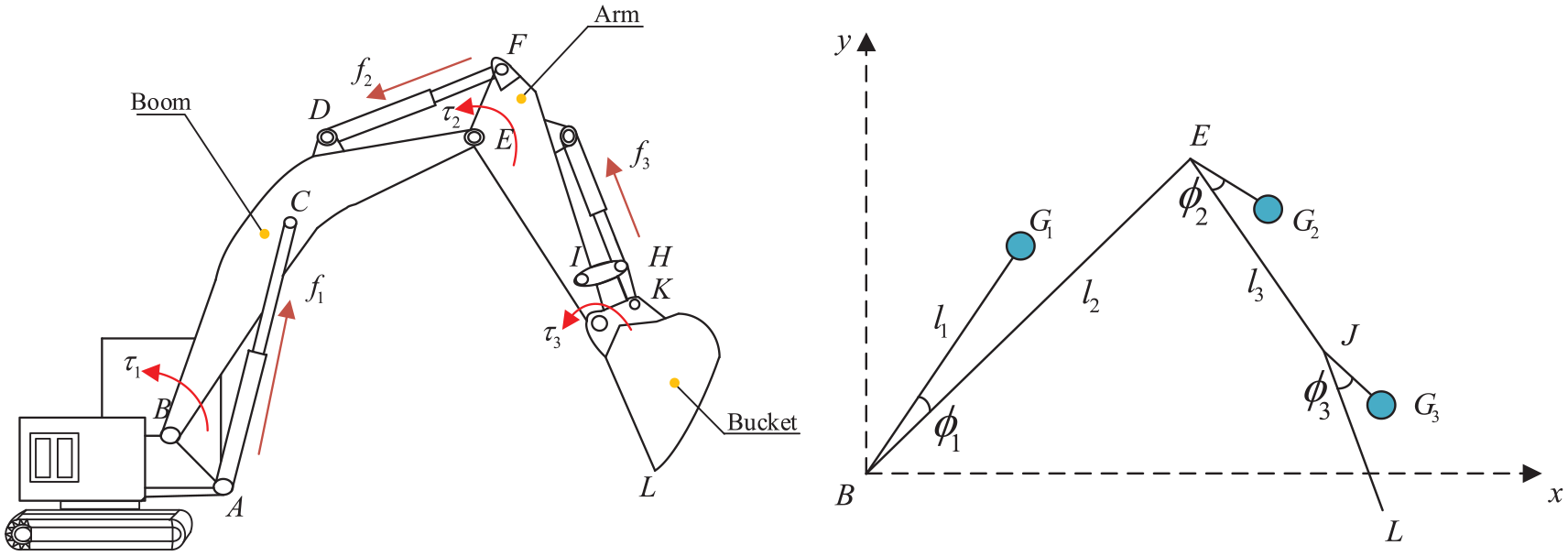
Dynamic model of the working device of the autonomous excavator.
When solving the dynamic model of the manipulator, the Lagrange technique does not need to consider the internal force of the rod26,27 where l1, l2, and l3 are the distance from the center of mass of the boom, arm, and bucket to the joint rotation axis, respectively.

Based on the balance principle, the Lagrangian function is established as follows:

where L is the Lagrangian operator, which represents the difference between the kinetic energy and the potential energy of the system.
The kinematic model is shown in Figure 2.
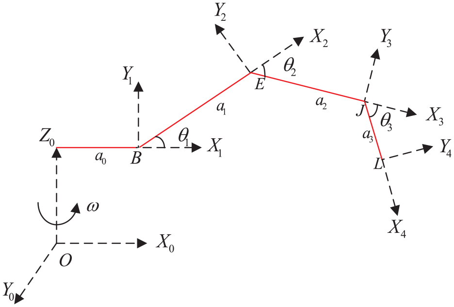
Kinematic model of working device.
where
The total kinetic energy of the manipulator of the excavator is the sum of the translational energy and the rotational kinetic energy of the center of mass. When the excavator walking device is not in the driving state, only the rotational kinetic energy of the manipulator is considered. The rotational kinetic energy formula of the excavator is as follows:
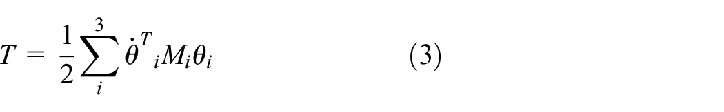
where

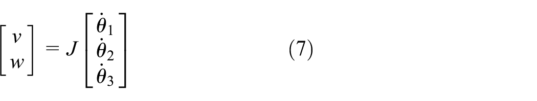
where v is the linear velocity of the manipulator and w is the angular velocity of the manipulator. The mass of the boom, arm, and bucket of the manipulator is simplified to the centroid to calculate the Jacobi matrix of the manipulator; the centroid positions of the boom, arm, and bucket are as follows:

The Jacobian matrix calculation formula of the excavator’s manipulator is:

where
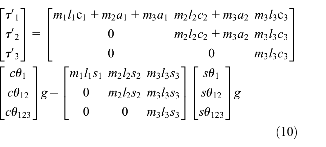
The specific formula is shown in Appendix A (A-1), and the joint torque of the manipulator can be expressed as follows:

where
Related parameter identification and online dynamic compensation
Online gravity compensation and related parameter identification
The weight of the excavator’s manipulator is large. During the operation, the dynamic characteristics of the boom lifting, the arm, and the bucket are greatly affected. If the online compensation calculation of the excavator boom, arm, and bucket is carried out, the parameters such as
Firstly, in the test, the pressure sensor is used to measure the driving force f1, f2, f3 of the hydraulic cylinder under different attitudes and no-load conditions, as well as the displacement y1, y2, y3 of the boom, arm, and bucket hydraulic cylinder at the corresponding time, and the joint angles θ1, θ2, θ3 at this time are obtained by using the forward kinematics solution. At this time, the driving force generated by the change of the hydraulic cylinder is the Coulomb friction, the viscous friction, and the external force along the direction of the hydraulic cylinder caused by self-gravity. Since the influence of the first two is far less than the influence of self-weight, it is assumed that the combined external force is approximately equal to the external force generated by self-weight, that is fg1, fg2, fg3. In this instantaneous state, the driving force of the excavator manipulator is:

At this time, the dynamic equation of the three joint torques
where c1 = cos
The driving force of a hydraulic cylinder is the key to generate driving torque. The distance from the force to the shaft is the intermediate medium for the conversion of driving force and torque.
According to Figures 3–5. the relationship between the driving force arm or equivalent length of each cylinder and the length of the cylinder body is obtained by geometric method.
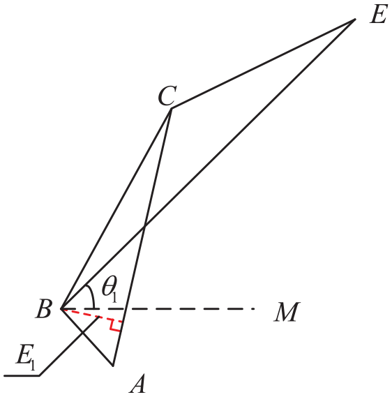
Structural analysis diagram of boom device.
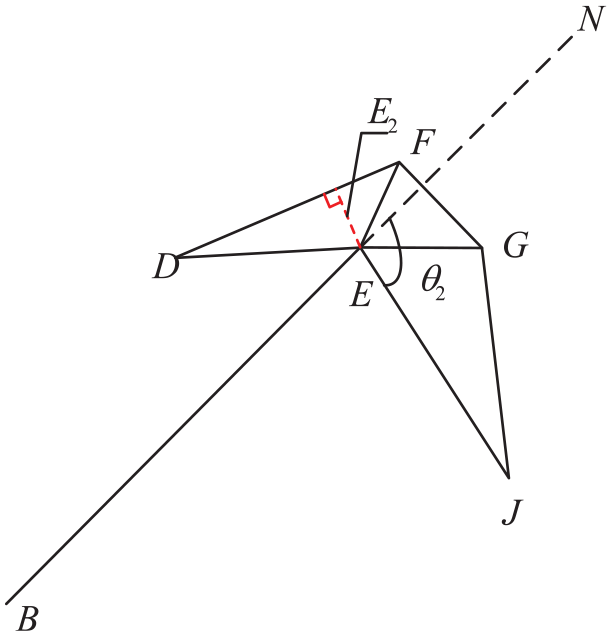
Structural analysis diagram of arm device.

Structural analysis diagram of bucket device.
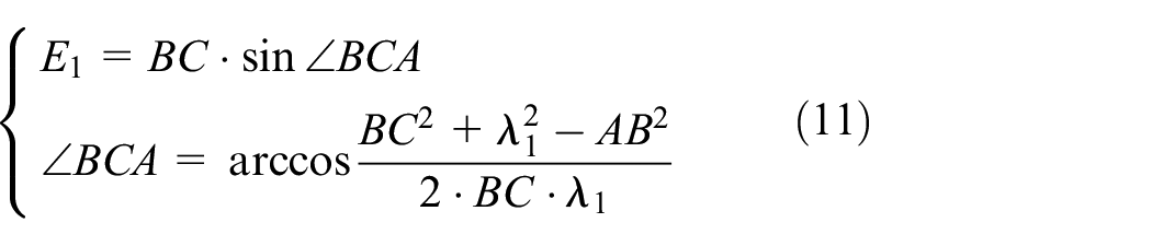
The driving arm E1 of the boom hydraulic cylinder is:
The driving arm E2 of the arm hydraulic cylinder is:
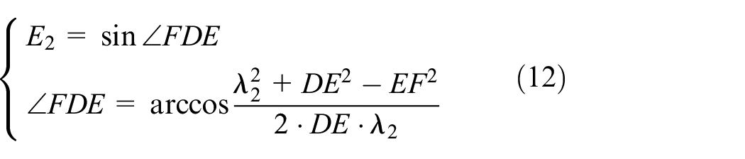
The driving arm E3 of the bucket hydraulic cylinder is:
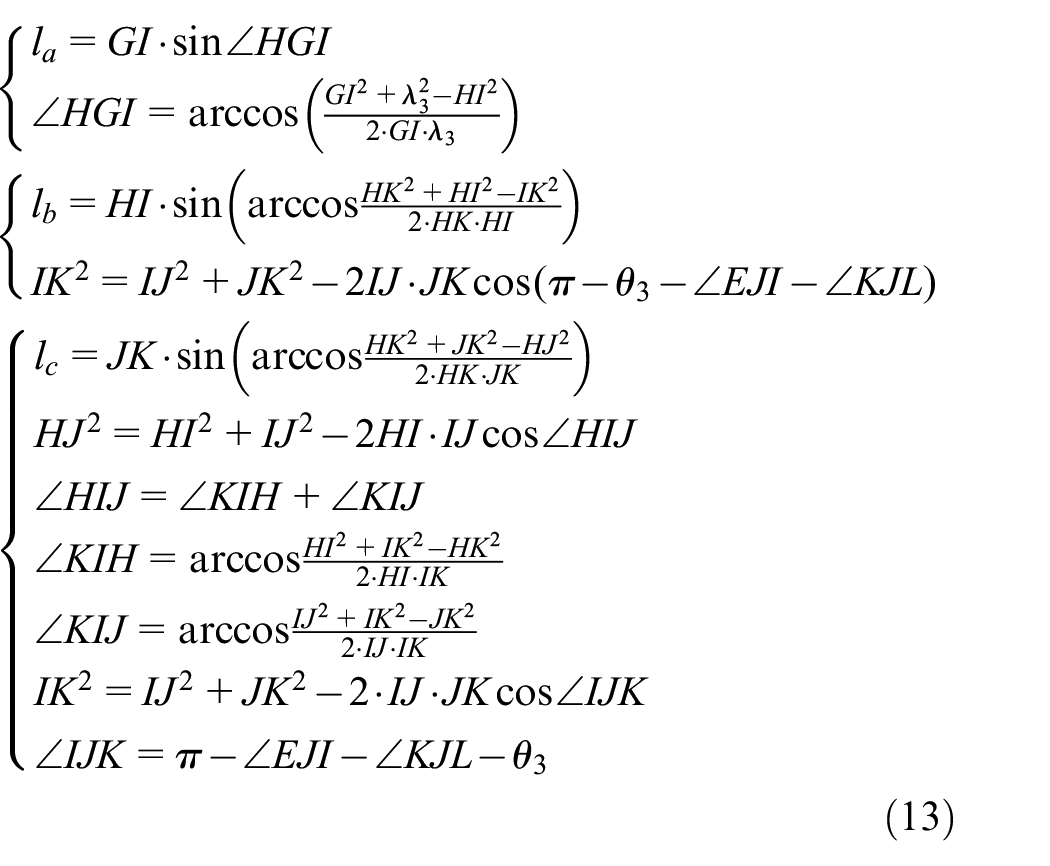
The above
According to θ1, θ2, θ3 derived from inverse kinematics, the external forces fg1, fg2, fg3 caused by self-weight are calculated as:

Secondly, The joint angles θ1,θ2,θ3 and driving torque
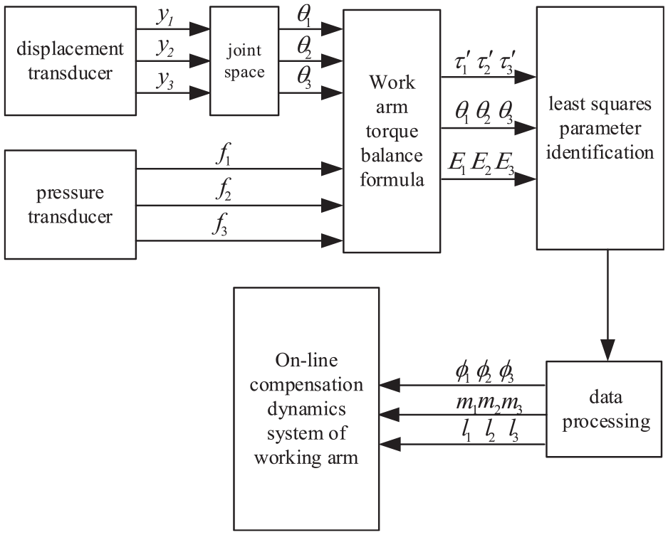
Derivation process diagram of relevant parameters.
All the parameters in the
Online centripetal force term and inertial force term compensation
The inertia force and centripetal force created by the enormous weight of the manipulator will affect the motion control precision of the excavator operation, so the centripetal force and inertia force must be compensated online.
The inertial force term is:
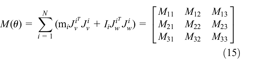
The centripetal force term is:
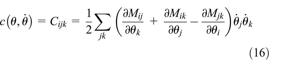
The relevant parameters identified in the previous section are substituted into Formulas (15) and (16) to obtain the specific inertial force term and centripetal force term. The formulas are detailed in Appendix A (A-2, A-4).
Combined with the previous section, the online compensation model of gravity, centripetal force, and inertial force can be obtained. The driving force of the boom, arm, and bucket hydraulic cylinder measured by the force sensor during operation is f1, f2, f3. The driving force after the external interference force fe1, fe2, fe3 in the direction of the compensated hydraulic cylinder can be used as the driving force fR1, fR2, fR3 of the hydraulic cylinder under actual conditions, which is:
Manipulator hydraulic system
Valve-controlled asymmetric cylinder
The boom hydraulic cylinder, arm hydraulic cylinder, and bucket hydraulic cylinder are the three hydraulic cylinders utilized in the excavator manipulator. The expansion and contraction speed of the hydraulic cylinder is determined by the valve opening of the electro-hydraulic proportional valve in this system. The relationship between the control signal and the expansion amount of the hydraulic cylinder can be determined. Figure 7 depicts a valve-controlled asymmetric hydraulic cylinder system.
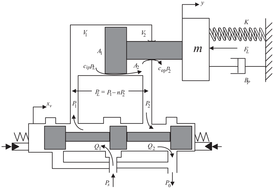
Control diagram of valve-controlled asymmetric hydraulic cylinder.
The servo amplifier in the controller converts the voltage signal to a current signal. This process is a purely proportional phase, and the transfer function is expressed as:
where I is the output current, U is the input voltage,
In this section, the flow characteristics of the servo valve are simplified as a second-order oscillation link, which is expressed as:
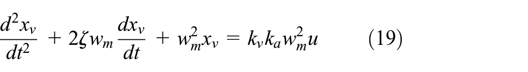
where xv is the slide valve displacement of the main valve, wm is the natural frequency of the servo valve, u is the input servo valve voltage signal, and kv is the servo valve flow gain.
The load flow equation, hydraulic cylinder flow equation, and hydraulic cylinder force balance equation are all included in the valve-controlled asymmetric hydraulic cylinder.
The linear flow equation of the servo valve can be written as:

where QL is the load flow, PL is the load pressure, Kq is the flow gain, and Kc is the flow pressure coefficient.
The load flow formula of the hydraulic cylinder is as:

where v represents the piston speed, the equivalent leakage coefficient of the Ctp system, Ve represents the entire volume in the hydraulic cylinder cavity, βe represents the effective bulk modulus of the system., and Ame represents the effective cross-sectional area of the piston.
The motion equation of the piston is as:
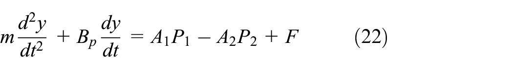
where A1 and A2 are the piston area of the rodless cavity and the rod cavity respectively, K is the load stiffness coefficient, y is the displacement of the hydraulic cylinder,
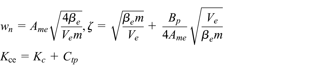
The Laplace transform of equations (20), (21), and (22) is performed without taking leakage into account. The following is the transfer function of the input spool displacement to the piston displacement of the hydraulic cylinder:
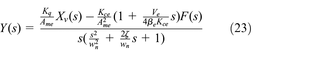
where wn is the natural frequency of the hydraulic cylinder piston,
Valve-controlled hydraulic motor
The slewing device of the excavator is an important part of motion control. In this paper, the transfer function of the valve-controlled hydraulic motor is as follows:
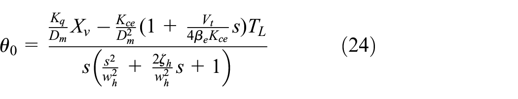
where
Tracking control strategy and simulation analysis
Control objective
The trajectory of the autonomous excavator is planned based on the needs of the work.28,29 This section defines the point-to-point trajectory path of the manipulator bucket’s tooth.
In this section, the interpolation method is selected to calculate the trajectory planning. Eight key points of excavation are set in the excavation trajectory. To facilitate the subsequent planning of the excavation stage, the joint angle trajectory between each two points of the boom, arm, and bucket can be expressed by an interpolation polynomial. The angular velocity of the joint can be expressed by the first derivative of the polynomial, and the angular acceleration of the joint can be expressed by the second derivative of the polynomial. The general formula for trajectory planning of boom, arm, and bucket is established as follows:
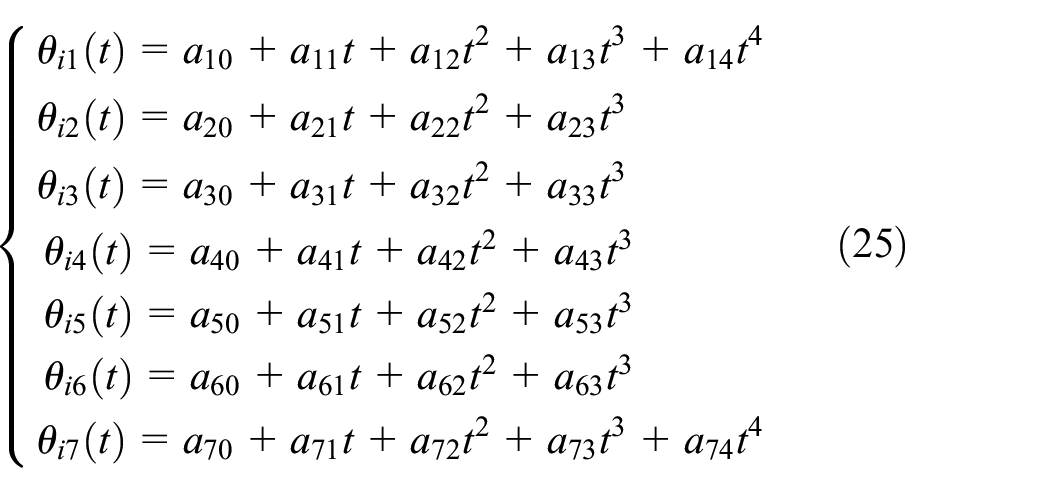
where
The optimization goal of this research is to lower the manipulator hydraulic cylinder movement stroke by reducing the change of the joint angle. The optimization objective function is as follows:
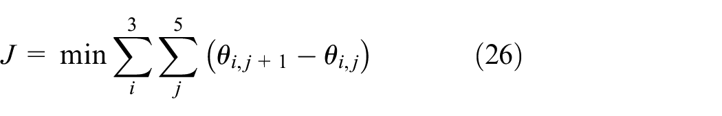
where i represents the i th joint angle. j represents the key point of the mining path at j.
The constraint function is shown in Formula (27):
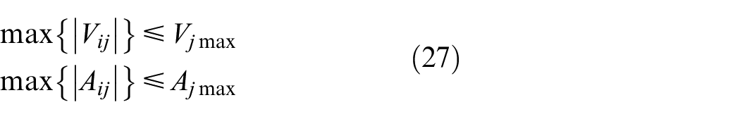
where Vij is the angular velocity of the i th joint angle in the j-segment. Aij is the joint angle acceleration of the i th joint angle in the j-segment; Vjmax and Ajmax represent the maximum angular velocity and angular acceleration limit of the corresponding joint angle, respectively.
For the modified autonomous excavator, the trajectory planning of the pose space is optimized and transformed into the joint angle of the joint space. The joint angle and angular velocity of a mining planning are shown in Figure 8.
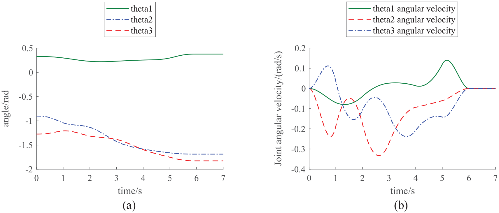
Joint angle planning. (a) Joint angle and (b) joint angular velocity.
Control strategy
The precise motion control strategy diagram of the manipulator of the autonomous excavator is shown in Figure 9. The traditional control strategy usually does not compensate for the external disturbance to the hydraulic system caused by the manipulator model itself in the dynamic model. In this paper, the dynamic online compensation method is used to compensate for the external interference force in the direction of the hydraulic cylinder generated during the operation of the manipulator. It effectively eliminates the influence of external interference during the movement of the manipulator and improves the motion control accuracy of the excavator manipulator.
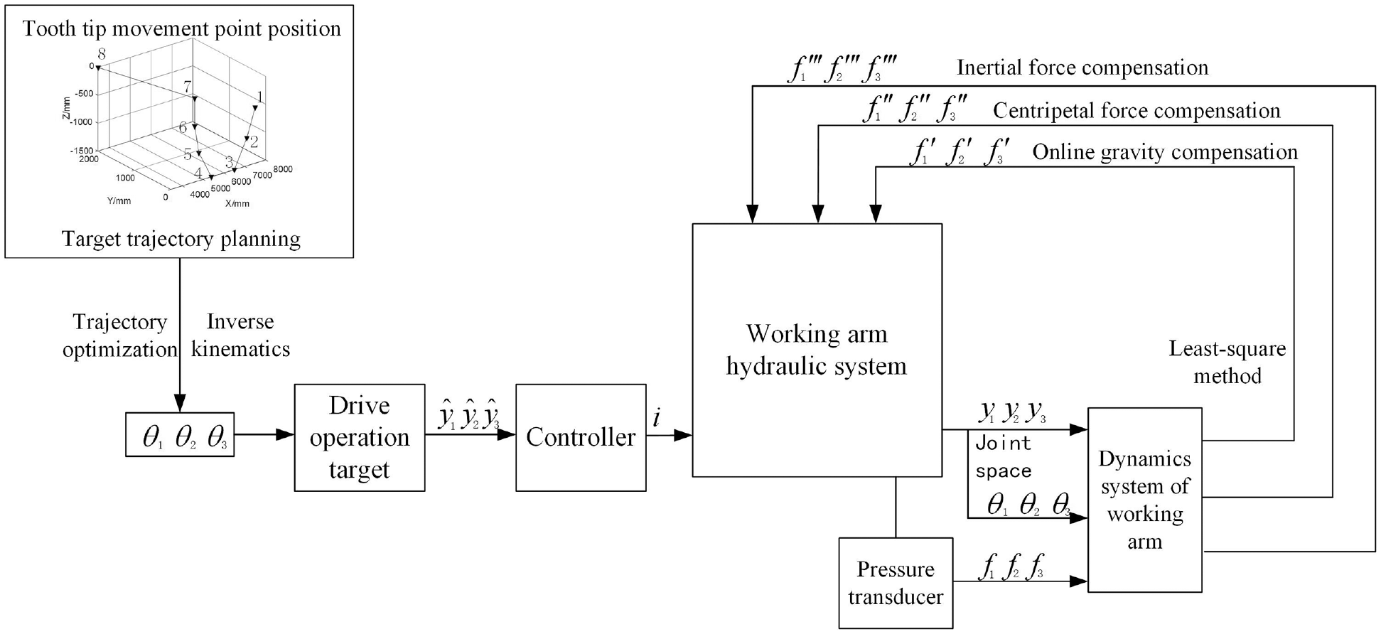
Precise motion control strategy of the manipulator of the autonomous excavator.
Define the tracking error of the system as:

Define the sliding surface of the system as:

Among them,
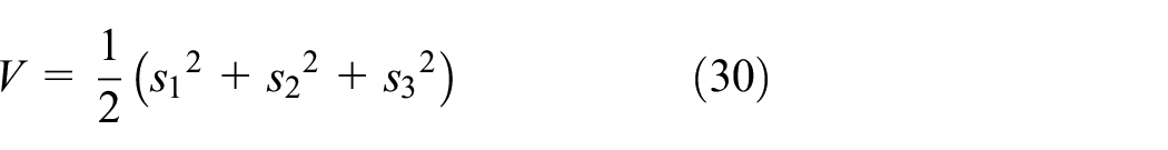
Construct the Lyapunov function as:
Set the control force to:

where

It indicates that the designed control method is asymptotically stable, and the tracking error and its derivative approach 0 over time.
Simulation analysis
In the typical trapezoidal excavation environment, the simulation results of online compensation and without online compensation are compared using the developed autonomous excavator model as the control object. Figure 10 depicts the comparative simulation results with and without online compensation adjustment.
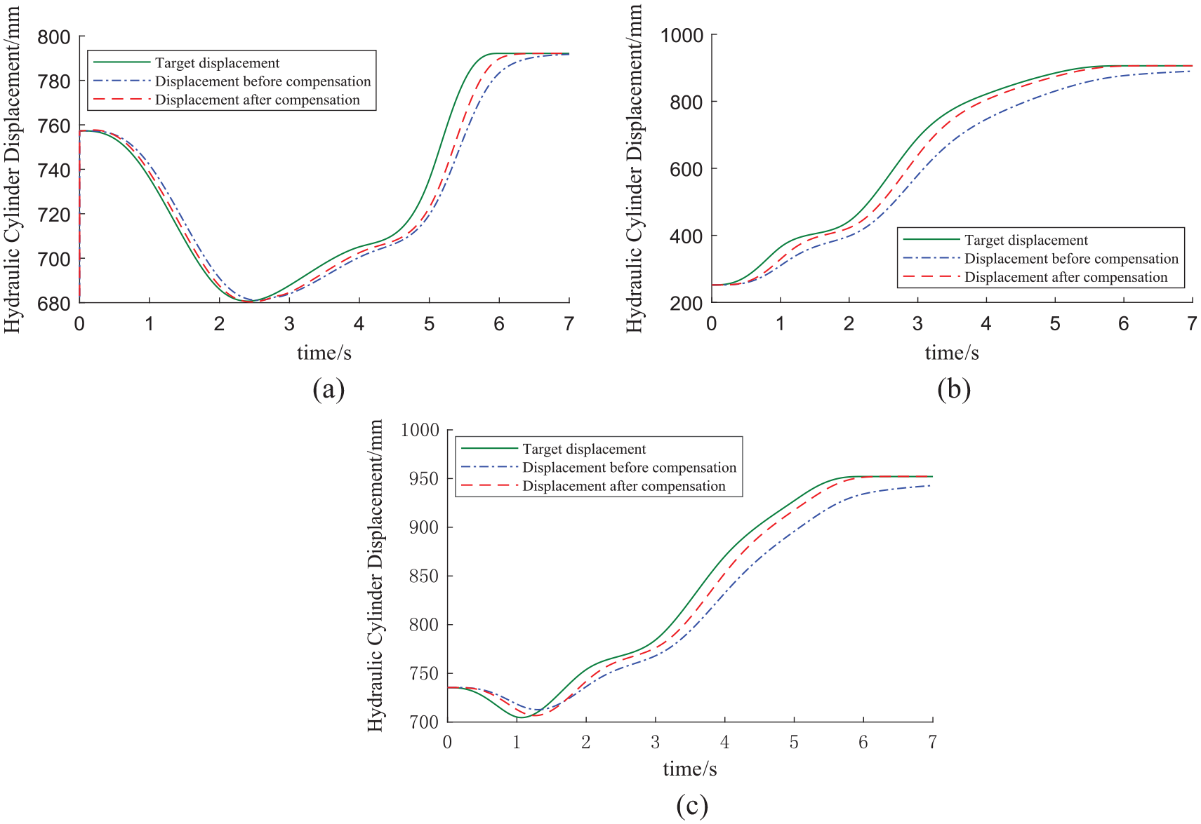
Displacement tracking curve of hydraulic cylinder. (a) Hydraulic cylinder displacement of the boom, (b) hydraulic cylinder displacement of the arm, and (c) hydraulic cylinder displacement of the bucket.
By substituting the trajectory planning path into the online compensation dynamic model, the gravity torque compensation, centripetal moment, and inertia moment generated during the movement of the manipulator can be obtained and the compensation amount is used in the system. Figure 11 depicts a time domain simulation of gravity moment compensation, centripetal moment compensation, and inertia moment compensation.
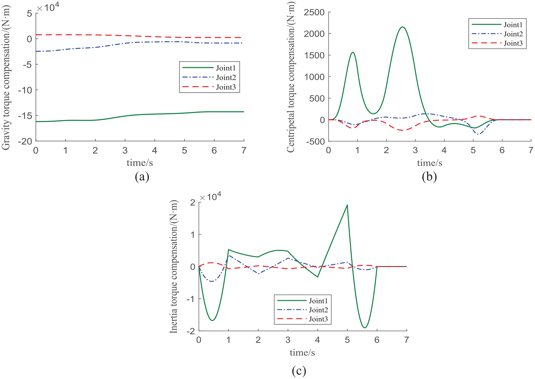
Online compensation of gravity, centripetal force, and inertia moment. (a) Gravity torque compensation, (b) centripetal force moment compensation, and (c) inertia moment compensation.
In the case of the reciprocating motion of the bucket hydraulic cylinder is stationary, the time domain curve of the driving force and displacement of the hydraulic cylinder are obtained by simulation as shown in Figure 12.
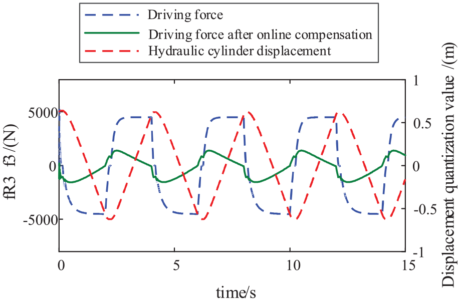
Bucket compensation result.
The excavator manipulator needs to overcome the external interference to work which consumes some energy and affects the trajectory tracking effect during the operation process. The driving force after online compensation in the figure changes near 0. It can be seen that the online compensation control strategy effectively compensates for the inertia force, centripetal force, and gravity torque. The force change of the driving force enables the excavator manipulator to eliminate the influence of inertia, centripetal force, and gravity on the movement of the manipulator during the operation process, which can improve the working accuracy and efficiency of the autonomous operation of the excavator.
Test
The test equipment of the autonomous excavator is shown in Figure 13. The joint angle measurement units at the boom and arm are installed on their respective outer surfaces; the bucket uses a built-in displacement sensor, and the pressure sensor is installed at the inlet and outlet of the hydraulic cylinder pipeline. The bucket tooth tip space error is measured by the full transfer point method.
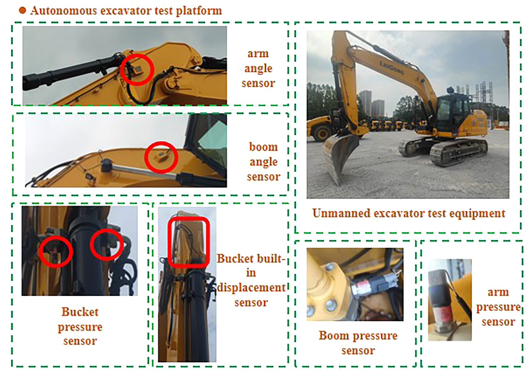
Autonomous excavator test platform.
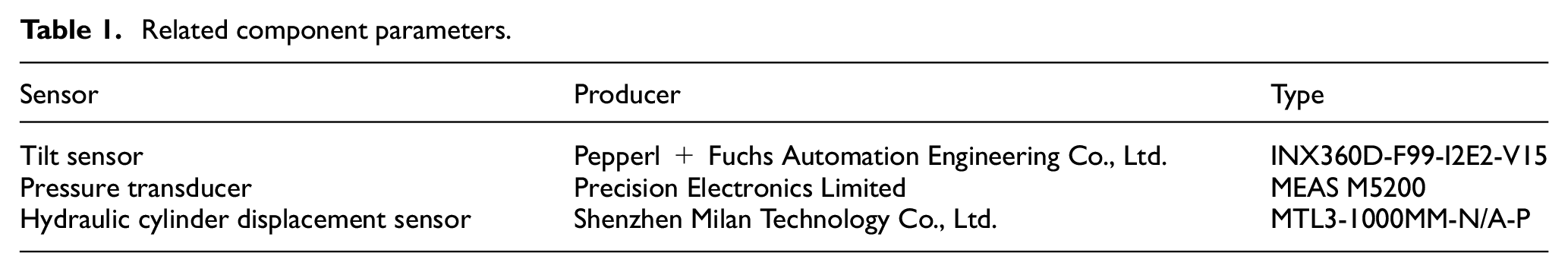
The four degrees of freedom of the manipulator and the rotary device of the autonomous excavator are driven by the hydraulic servo. To make the manipulator reach the target point accurately, the inclination sensor is installed at the rotation, boom, and arm shaft. A built-in displacement sensor is installed in the bucket hydraulic cylinder. During the operation process, the inclination sensor and the built-in length sensor transmit the collected data to the controller through the data bus, and obtain errors by comparing with the planned path of the joint angle, thereby achieving closed-loop control of the joint angle is carried out. The relevant component models are shown in Table 1.
Related component parameters.
In order to verify the effectiveness of the control strategy, the manipulator adopts the method of simulating tracking and excavating the trapezoidal path for experimental verification. Through the excavation trajectory planning introduced in the previous section, the initial position of the manipulator is set according to the initial position of the excavation trajectory planning, so that the relevant joint angle is consistent with the planned initial joint angle, and then the tracking motion control is performed. In the case of bucket load, the online compensation control strategy is compared with the non-compensation control strategy. Using the above sensors to measure the joint angle and the hydraulic cylinder displacement feedback to the controller for the excavator arm tracking control. The test results are as follows:
It can be seen from Figure 14 that compared with the uncompensated manipulator control, the bucket tooth tip tracking accuracy after online compensation is significantly improved. Due to the large combined mass of the boom and its hydraulic cylinder and the load of the bucket, the tracking accuracy of the joint angle of the boom and the bucket increases obviously, and the tracking accuracy of the joint angle of the bucket rod is also greatly improved compared with that without compensation. The results are shown in Table 2.
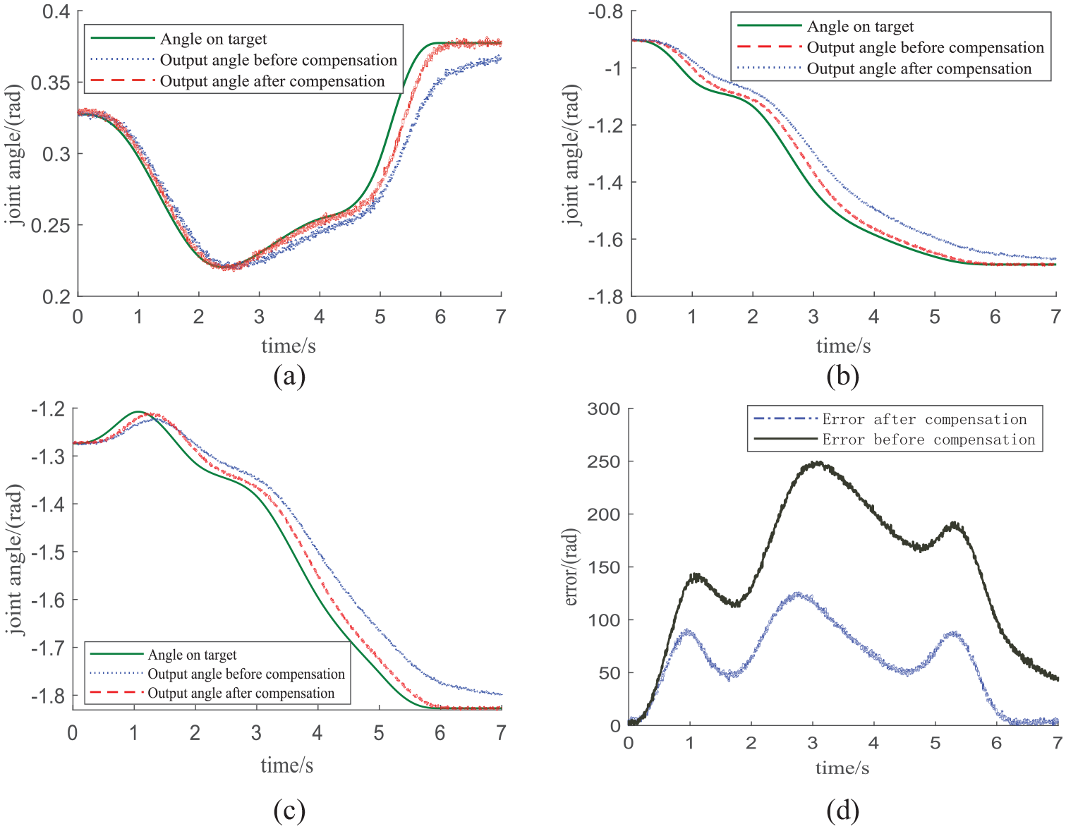
Tracking under load. (a) Boom joint angle, (b) arm joint angle, (c) bucket joint angle, and (d) bucket tooth tip tracking error analysis.
Performance index comparison.

It can be seen from Table 2 that under the load of the bucket, the maximum error of boom joint angle tracking decreased by 43.14% respectively, the maximum error of arm joint angle and bucket joint angle tracking decreased by 26.56 and 51.05% respectively, and the average error of the whole trajectory are reduced by 56.41, 61.33, and 64.26% respectively, and the maximum error of bucket tooth tip space position tracking decreased by 50.42%. It can be seen that the online compensation control strategy and control strategy can effectively improve the control accuracy of the working device system of the autonomous operation excavator, and increase the operation accuracy and tracking performance of the manipulator of the autonomous operation excavator.
Conclusions
In this paper, the influence of gravity center, centripetal force, and inertial force on the control accuracy of the manipulator of the system autonomous excavator is studied by using the method of on-line compensation of external interference of hydraulic cylinder. The motion control strategy of the manipulator is proposed, and the simulation analysis and test are carried out. The main conclusions are as follows:
(1) The dynamic model of the autonomous excavator is established. The least square method is used to identify the dynamic model parameters of the excavator manipulator. The external interference of the bucket hydraulic cylinder is compensated online.
(2) The trajectory planning provides the trajectory control target of the autonomous operation excavator, and the autonomous operation test of the excavator is performed. The feasibility of the online compensation algorithm is verified, and the online compensation control strategy improves the autonomous operation accuracy of the excavator.
(3) The test results show that the online compensating control strategy improves the tracking performance of the autonomous excavator in manipulator self-tracking. This is of great significance to improve the tracking accuracy and increase the working efficiency of excavator autonomous operation.
Footnotes
Appendix A
In the formula, θ12 = θ1 + θ2, θ123 = θ1 + θ2 + θ3.The above
In the formula,
Acknowledgements
We gratefully acknowledge the support and contribution from Yanshan University, China.
Handling Editor: Chenhui Liang
Declaration of conflicting interests
The author(s) declared no potential conflicts of interest with respect to the research, authorship, and/or publication of this article.
Funding
The author(s) disclosed receipt of the following financial support for the research, authorship, and/or publication of this article: This work was supported by the Natural Science Foundation of Hebei Province (E2021203145) and the National Natural Science Foundation of China (No.52175063).