
Abstract
To elucidate the influences of the outlet position of splitter blades on the performance of a low-specific-speed centrifugal pump, two different splitter blade schemes were proposed: one located in the middle of the channel and the other having a deviation angle at the trailing edge of splitter blade toward the suction side of the main blade. Experiments on the model pump with different splitter blade schemes were conducted, and numerical simulations on internal flow characteristics in the impellers were studied by means of the shear stress transport k-ω turbulence model. The results suggest that there is a good agreement between the experimental and numerical results. The splitter blade schemes can effectively optimize the structure of the jet-wake pattern and improve the internal flow states in the impeller channel. In addition, the secondary flow and inlet circulation on the pressure surface of main blade, the flow separation on the suction side of splitter blade, the pressure coefficient distributions on blade surface can achieve an evident amelioration when the trailing edge of splitter blade toward the suction side of the main blade is mounted at an appropriate position.
Keywords
Introduction
The low-specific-speed centrifugal pump has the advantage of high head and compact structure. It is widely applied in field of petrochemical industry, power process industry, aerospace industry, and so on. However, as the long and narrow shape of the blade channel, low-specific-speed centrifugal pumps are easy to generate the head-flow curves, low efficiency and instability phenomenon during normal operation.1,2
In the field of turbine machinery, adding splitter blades in the middle-to-outlet of impeller passages has been proved to improve the performance of machinery effectively,3–5 by decreasing the blockage at the impeller inlet, optimizing the velocity distribution in the impeller and reducing the pressure fluctuations. Gölcü and colleagues6,7 investigated the effects of blade number and splitter blade length on pump performance and found that splitter blade only shows a positive effect when the blade number less than 5 and bigger discharge angles should be applied to get better performance. Besides, the author proposed an artificial neural network model from the experimental data to model the pump performance with splitter blades, which shows a good agreement with the test. Choi et al. 8 built the relationship between the flow field and the pump performance for a very-low-specific-speed centrifugal pump, revealing that large reverse flow at the impeller outlet causes the decrease in the head. Kergourlay et al. 9 proved that the splitter blades result in a more uniform distribution of velocities and pressures inside the propellers and reduce the pressure fluctuations at the discharge pipe. Shigemitsu et al. 10 reported that the splitter blades in a mini centrifugal pump can suppress backflow in the rotor, increase volute efficiency, and decrease the vortex loss. Cavazzini et al. 11 compared the suction performance of model pump without and with splitter blade by means of experiments and simulations. The results showed that adding the splitter blade results in illustrious improvement of suction performance at large flow rate conditions and a decrease at low flow conditions instead.
Much research has been conducted on the internal flow characteristic and energy loss analysis in the fluid machinery. Choi et al. 12 studied the internal flow characteristics in several types of closed and semi-open impellers for a low-specific-speed centrifugal pump. The results showed that the reverse flow at impeller exit of the semi-open impeller impaired the pumping head seriously. Y Li et al. 13 investigated the unsteady flow characteristics at low flow rate in a centrifugal pump by numerical simulation and a visualization experiment. The results indicated that the backflow and pre-rotation are the important reason responsible for the drop in pump performance. Entropy generation analysis, which is directly originated from the second law of thermodynamics and has more advantages than traditional energy conservation method, can be used in all energy conversion systems and very useful for engineering system design and optimization. 14 Schmandt et al. 15 proposed a glass box optimization method for reducing pipe components losses based on the entropy generation and velocity data from computation fluid dynamics which was proved by using a 90° bend model. The entropy production theory was used by D Li et al. 16 to analyze the hump and hysteresis characteristics in a pump-turbine taking wall effect of entropy generation into consideration. The result showed good agreement with the traditional pressure drop approach and found that the main reason for these unstable phenomena is the presence of vortices in vanes near hub and the shroud and backflow at the runner inlet. X Li et al. 17 showed that entropy production rate in a centrifugal pump is consistent with the head-drop curve and increases sharply at the fully developed cavitation stage.
In this article, three different types of centrifugal impeller are investigated for the performance analysis: one 6-blade impeller without splitter blades and another two splitter blade impellers which have different deviations of splitter blade outlet position in relation to the suction side (SS) of main blade. The particle image velocity (PIV) test and numerical simulation are carried out to investigate the relationship of pump performance and internal flow characteristics inside the low-specific-speed pump. The performance curves are compared to obtain a better deviation angle of splitter blade outlet position. The velocity contours, streamline distribution, entropy generation rate, pressure and blade loading distributions are analyzed to illustrate the differences of three schemes.
Model pump and experiment configuration
Geometrical model
The main design parameters in the low-specific-speed centrifugal pump are as follows: nominal flow rate Qn = 2.78 kg/s, head H = 8 m, rotational speed n = 1450 r/min, and the non-dimensional specific speed ns = 59. The prototype pump has an impeller with six regular cylinder backward blades and a spiral volute to raise the pressure and reduce hydraulic loss. According to the main design parameters, two splitter blade impeller schemes (schemes 1 and 2) with four main blades and four splitter blades were designed. The detail parameters of three different impeller schemes are listed in Table 1. The dimensions of the impellers are shown in Figure 1, and photographs are shown in Figure 2. The difference between schemes 1 and 2 is the location of splitter blades: either in the middle of main channel (scheme 1) or the trailing edge of splitter blades deviated to the SS of the main blade by 12° (scheme 2). The leading edges of splitter blades in both schemes are installed at the same position in impeller channels.
Main geometrical parameters of the three impellers.

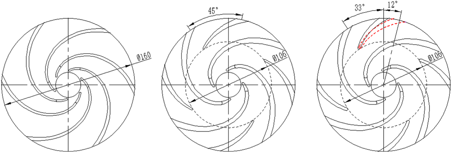
Three impeller schemes: (a) prototype, (b) scheme 1, and (c) scheme 2.

Three tested scheme impellers: (a) prototype, (b) scheme 1, and (c) scheme 2.
Experiment configuration
The pump performances were tested in the open test rig shown in Figure 3. Two static pressure sensors (uncertainty 0.1%) were installed at pump inlet and outlet to capture pressure signals. An electromagnetic flow meter and a torque meter with same uncertainty of 0.03% were used to measure the flow rate and shaft torque, respectively. The error of the shaft encoder was 0.005% for reading the rotation speed. The performance data were acquired by the data acquisition system at several different flow rates.

The test rig configuration.
As an important flow measurement method, PIV technology was adopted to measure the internal flow field of the impeller in this study. In order to allow for optical access, the impellers, blades, volute, and suction pipe were manufactured by means of transparent polymethyl methacrylate, as can be seen in Figures 2 and 3. Meanwhile, as the width of volute is 18 mm, the cross section was designed to be rectangular to make better optical access. The Insight 3G-2DPIV system was used to measure the two-component velocity fields normal to the rotating shaft in the mid passage-width of the impeller. Due to the obstruction of the suction pipe, the whole flow field was not able to be captured directly by camera. Therefore, a mirror at an angle of 45° with the measurement plane, suction pipe, and the camera, respectively, was mounted in front of the impeller and the camera shot in the direction normal to the image in the mirror.
The laser source from YAG-NEL was operated at maximum output energy of 200 mJ per pulse duration of 3–5 ns and the frequency of laser pulse was 30 Hz. The thickness and diameter of light sheet are approximately 1 and 3.5 mm, respectively. The seeding particles, silvered glass particles, are of spherical shape and have a diameter between 10–15 μm and the density of 1.6 g/cm3, a little larger than water. It has the characteristics of synchronism, scattering, nontoxic and non-corrosive, stable chemical property, low price, and so on. The CCD Camera 630059 (4 MP) (spatial resolution of 2048 px × 2048 px) took the images of the flow field. The frame rate is 16 fps and the minimum interval time is set to 200 ns. The photographs and data acquisition and analysis were finished by the Insight 3G-2DPIV system. In this experiment, the time interval and delay between the two pulses were set to 100 and 345 μs, respectively. For each case, 300 pairs of cross-correlation images were captured and analyzed.
Numerical simulation
Mesh generation and numerical model
For this model pump, the entire computation domain includes the suction pipe, wear ring, front cavity, impeller, volute, and back cavity, as shown in Figure 4. The mesh was generated by means of commercial ANSYS-ICEM code. The tetrahedron unstructured mesh was generated for impeller and hexahedron structured mesh for other parts to reduce the mesh number. The grid refinement technology was employed in some key parts of impeller and cut water region of volute to capture complex flow patterns, the detailed mesh as shown in Figure 5. The interfaces between connection parts were specially treated to guarantee the similar grid number at both sides. Several different mesh numbers were chosen to check mesh independence in head prediction. The head maintained stable with the increase in the grid number when the total grid number was larger than 3 million. Considering the computation accuracy and resource, the final mesh number for calculation of the prototype, scheme 1, and scheme 2 were 3.236, 3.170, and 3.152 million with similar values, respectively. Except for the impeller, the shared components of suction pipe, wear ring, front cavity, back cavity, and volute in three schemes had the grid numbers of 218,784; 65,856; 285,432; 301,668; and 889,366; respectively.
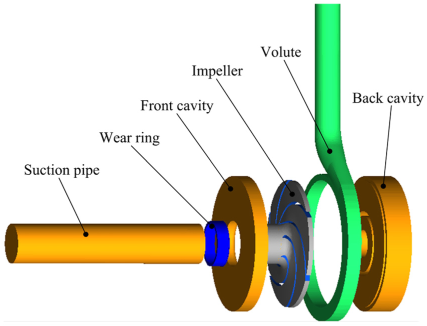
The three-dimensional computation model.
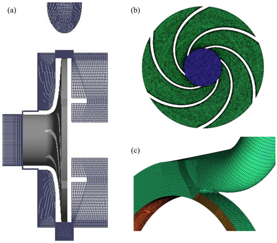
The general view of mesh: (a) calculation domains, (b) impeller domain, and (c) volute domain.
Numerical simulation setup
The flow field inside the low-specific-speed centrifugal pump was calculated with commercial software ANSYS CFX by solving three-dimensional unsteady Reynolds averaged Navier–Stokes equations (3D-URANS). The finite-volume method was adopted for the discretization of control equation in this code. The flow inside the centrifugal pump was assumed to be continuous and incompressible. The flow model was complemented with shear stress transport (SST) k-ω turbulence model. 18 Automatic wall function was selected in the near wall treatment by which boundary layer can be resolved with a small number of grid points. 19 The second-order backward Euler and high resolution were selected as the discretization schemes of time and space, respectively. The constant total pressure and mass flow rate were imposed as the boundary conditions at the inlet and outlet of computation model, respectively. The roughness value of the model surface was set to 1.6 µm, consistent with the real suction pipe, discharge pipe, impeller, and volute. As the impeller is the only moving part in the low-specific-speed centrifugal pump, the multiple frame of reference was applied, the rotation frame of reference for the impeller and the stationary frame of reference for other parts. In the steady simulation, the frozen stator method was selected between rotating impeller and stationary volute (suction pipe), considering the centrifugal effect in the flow. 20 When the calculation residuals reached 1 × 10⁻⁵, the simulation was considered to converge well.
Experimental tests
Comparison of test performances
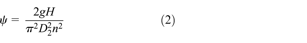
The comparisons of pump head and efficiency tests among the three impeller schemes are shown in Figure 6. The flow rate and head were normalized as flow rate coefficient φ and head coefficient ψ by the following equations

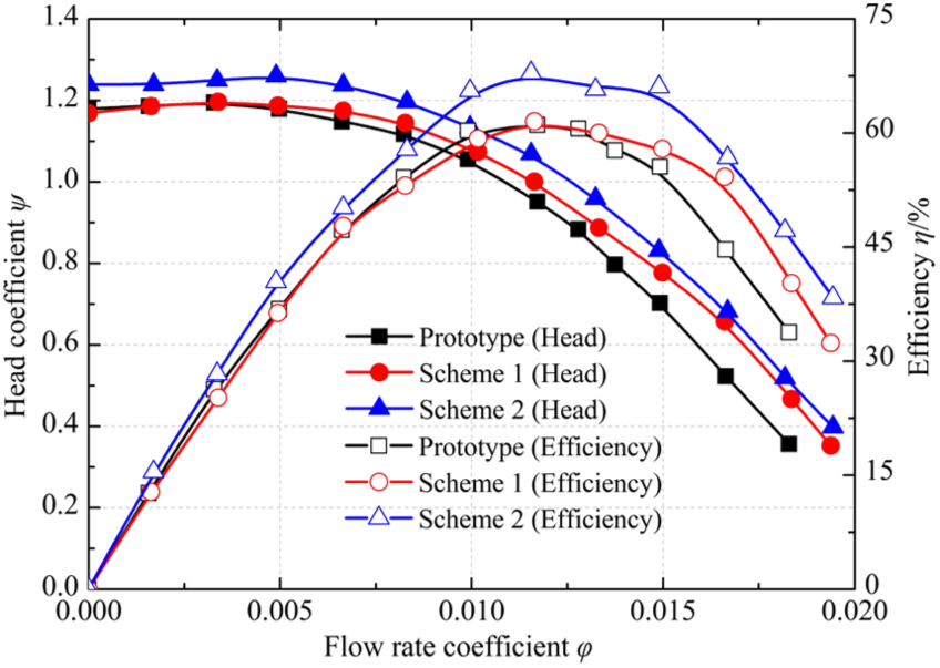
Head and efficiency test performance for the three schemes.
In both scheme 1 and scheme 2, the head and efficiency improved a lot than the prototype at all operation conditions. Compared to the prototype, the head increases by 5.16% and 13.2% and the efficiency increases by 0.8% and 9% at flow rate 3.15 kg/s (the best efficiency point flow rate) in scheme 1 and scheme 2, respectively. Therefore, adding splitter blades shows an effective and positive influence on the pump performance. Meanwhile, deviating the splitter blade trailing edge toward the SS of main blade by 12° in scheme 2 conduces to higher performance. Therefore, in order to analyze and verify this influence of the outlet position of splitter blade on the internal flow characteristics and pump performance in the low-specific-speed centrifugal pump, combined experimental tests and numerical calculations were utilized to analyze the main reasons affecting the performance of the pump at the best efficiency point flow rate.
Comparison between simulation and test
In Table 2, the numerical and test results of head and efficiency for three different schemes were compared at three different flow rates: 2.45, 3.15, and 3.85 kg/s. Maximum deviation errors between simulations and tests for each scheme are 5.8%, 2.4%, and 6.5% for the head, and 7.8%, 7.9%, and 3.6% for the efficiency at the three flow rates, respectively. The differences between simulations and tests are reasonable and acceptable. 21 Furthermore, in the PIV test, the radial and tangential components of absolute velocity in the impeller channel from pressure side (PS) to SS were obtained and compared to the corresponding results from numerical simulation at 0.8 and 0.9 times of impeller radius R2, as shown in Figure 7. From the plot in scheme 2, the relatively large error of radial velocity component between test and simulation was present relative to the prototype and scheme 1. But the test and simulation have similar variation trends in scheme 2. Meanwhile, based on the completely same numerical simulation settings and the errors of predicting the head and efficiency for three schemes, the reason for above phenomenon could be that the PIV test in scheme 2 has higher errors than the prototype and scheme 1. In general, the agreement between the PIV tests and the numerical results is good both qualitatively and quantitatively, which is the foundation of the following detailed numerical simulations.
Comparison of head and efficiency of three schemes at different flow rates.


Comparison of radial and tangential components of absolute velocity in impeller between PIV test and simulation at 0.8R2 and 0.9R2: (a) prototype, (b) scheme 1, and (c) scheme 2.
Results and discussion
Comparison of radial and tangential velocity contours
The contours of radial component of relative velocity for three schemes at the impeller outlet are shown in Figure 8, which is normalized by impeller outlet circumference velocity U2. It is obvious that the classical jet-wake pattern is present in the case of prototype impeller. The jet region has been established as the region of high radial velocity near PS of blade, while the wake region is close to the SS with low radial velocity. The similar situation can also be verified in other studies.22,23 The wake region which aggregates the energy losses that generated in the impeller is very significant for the impeller efficiency. Meanwhile, a large negative velocity region is found in the wake region near impeller hub of prototype, where strong reversed flow, jet-wake mixing, and interchange of momentum exist. These complex flow patterns lead to a substantial drop in hydraulic performance. In scheme 1 and scheme 2, however, the jet-wake region is cut substantially by the splitter blades. And, the negative velocity is suppressed, which is the reason that scheme 1 and scheme 2 have better performance than prototype. In addition, for scheme 1, the velocity distribution is more similar to the prototype, especially in the high radial velocity subchannel. The radial velocity near PS is obvious higher than that near SS in the subchannel. For scheme 2, the area of wake is smaller and the radial velocity distribution is more uniform. Therefore, adding splitter blades optimizes the structure of jet-wake region, which conduce to decrease the energy loss and improve the pump performance.

Contours of radial component of relative velocity at the impeller outlet.
Figure 9 exhibits the tangential component of absolute velocity Cu2 at impeller outlet normalized by impeller outlet circumference velocity U2 for three different schemes. According to Euler’s equation, the theoretical head equals to

Contours of tangential component of absolute velocity at the impeller outlet.
Comparison of streamline distributions
Streamline distributions at midspan and corresponding PS of main blade are shown in Figure 10. In the case of prototype propeller (Figure 10(a)), the streamline deviates from the blade shape seriously in the mid part of PS, which is the main region that affects the flow field and pump performance. Meanwhile, on the corresponding PS of main blade, the non-uniform streamline with a high curvature moves from hub to shroud near the blade rear part, resulting in secondary-flow loss. In scheme 1 (Figure 10(b)), the flow consistency at the midspan of main blade PS is better than the prototype, while the consistency between streamline and blade is worse close to the leading edge region of splitter blade. Furthermore, it is obvious that the inlet circulation locates the pressure surface of the main blade shroud. Compared to the prototype and scheme 1, scheme 2 has the optimized streamline distribution in the midspan, which has a better consistency with the blades shape, as shown in Figure 10(c). Besides, the secondary flow and inlet circulation attenuate on the pressure surface.

Streamline distributions at midspan (first row) and corresponding pressure side of main blade (second row): (a) prototype, (b) scheme 1, and (c) scheme 2.
Figure 11 represents the streamline on the SS of splitter blade in scheme 1 and scheme 2. For scheme 1, flow separation is observed in the hub and then flow into the downstream wake until the impeller exit which introduces energy loss.24,25 While on the SS of scheme 2, the flow separation is eliminated and the streamlines are optimized, flat, and smooth. Combining with Figure 10, it can be concluded that scheme 2 is superior in reassigning the flow distributions in the subchannels, which increases the flow rate in the channel between SS of splitter blade and PS of main blade. This leads to an increase in the axial velocity and a decrease in the incidence angle of flow, and hence, a suppression of flow separation on the SS of splitter blade.

Streamline distributions on the suction side of splitter blade for scheme 1 and scheme 2.
Comparison of entropy generation rate
The efficiency of pump can be divided into three parts: hydraulic efficiency, volume efficiency and mechanical efficiency. The head of pump can be measured by total pressure and velocity distributions, but it is rare to use a parameter to estimate the efficiency of the pump visually. Eckardt 23 found that in adiabatic machine entropy creation is a better parameter to measure the loss, which directly represents the destruction of work in the turbine machinery. In centrifugal pump, the entropy generation rate per unit volume σ 26 is defined as


where

Entropy generation rate in blade-to-blade view for three impeller schemes: (a) prototype, (b) scheme 1, and (c) scheme 2.
The entropy generation rate per unit volume in the volute near cut water region in midspan is presented in Figure 13. It is worthy to note the locations of highest entropy value: one in the cut water region and the other near the interface between impeller and volute. As the fluid lashes against the cut water region, it is one of the sources of instability flow and energy loss. Meanwhile, the inhomogeneous flow with jet-wake structures in the interfaces between impeller mixes and interacts, causing energy loss. As shown in Figure 13, the prototype and scheme 1 have larger high-entropy areas than scheme 2 at both locations afore-mentioned. It can be concluded that scheme 2 with splitter blades deviating to the SS has a better jet-wake flow structure in impeller outlet and less energy loss near cut water region.

Entropy generation rate in near cut water region for three impeller schemes: (a) prototype, (b) scheme 1, and (c) scheme 2.
Comparison of pressure coefficient
Figure 14 shows the development of pressure coefficient Cp on both PS and SS in midspan chord from main blades leading edge to trailing edge for the three impeller schemes. The pressure coefficient Cp is defined by

Distributions of pressure coefficient Cp on both pressure and suction sides of main blade for the three schemes.
As shown in Figure 14, Cp generally increases from leading edge to trailing edge of main blade, but is complex near the leading edge. Comparing the region near leading edge in scheme 1 and scheme 2, Cp on the PS of scheme 1 has an abrupt reduction, whose value is even lower than that on the SS. It is probably that fluid flowed into the channel is not consonant well with the shape of blade, leading to flow separation in this region, as manifest by the inlet vortex in Figure 10(b). Besides, focusing on the inlet region, scheme 2 has a larger pressure difference than scheme 1, which contributes to the energy transfer toward the fluid from blades. Furthermore, on the SS of scheme 2 also has a larger pressure coefficient than the prototype, which improves the cavitation ability because the cavitation often takes place in the SS of blade inlet regions. 28
The distributions of Cp on the PS near the impeller exit show that there is an abrupt change for the prototype impeller, which is obviously less than that for the splitter blade schemes at the same streamline position. The reason is that the control ability of blades to the fluid becomes weaker in this region, leading to violent changes of relative velocity and the appearance of unsteady flow patterns. This is also proved in Figure 10(a) on the PS of main blade. The difference in the pressure coefficient Cp between the PS and SS represents the work ability of blades or blade loading, which determines the value of head. This figure shows that scheme 2 has a higher main blade loading than scheme 1, explaining why scheme 2 has a higher head value.
Figure 15 presents the pressure coefficient Cp distribution on splitter blade in scheme 1 and scheme 2 along streamwise from leading edge to trailing edge of splitter blade. It rises with the increase in the streamwise location gently and consistently. Similar to that on the main blade, scheme 2 has a larger loading on the splitter blade than scheme 1. The pressure coefficient Cp on the SS in scheme 2 is always lower than that in scheme 1, while on the PS they are very close in the two schemes. It is attributed to the flow separation on the SS in scheme 1 as shown in Figures 10 and 11, which induces the streamline to deviate from the SS of splitter blade and to increase the curvature radius and finally the increase in the Cp on the SS. As a result, the blade loading and work ability of scheme 1 decrease, leading to lower head than scheme 2.

Distributions of pressure coefficient Cp on both pressure and suction side of splitter blade in scheme 1 and scheme 2.
Conclusion
Three impeller schemes (one prototype impeller without splitter blades and two splitter blade impellers) were proposed to improve the pump performance in the low-specific-speed centrifugal pump. The effects of the outlet position of splitter blades on the internal flow characteristics were analyzed by means of numerical simulations and physical tests, showing a good agreement. The difference in the two impellers with splitter blades is that the splitter blade trailing edge in scheme 2 deviates to the SS of the main blade by 12° while scheme 1 is without deviation. Various quantities, including the velocity contours, streamline distribution, entropy generation rate, pressure, and blade loading distributions, were adopted to verify and analyze internal flow characteristics inside the model pump for three different impeller schemes. Some conclusions are drawn as follows:
The outlet position of splitter blade has a significant impact on the performance of the model pump at all operation conditions. Compared to the prototype, the head increases by 5.16% and 13.2% and the efficiency increases by 0.8% and 9% at flow rate 3.15 kg/s (the best efficiency point) in scheme 1 and scheme 2, respectively.
Adding splitter blades can optimize the structure of the jet-wake region and improve the tangential component distribution of absolute velocity at impeller outlet, which is beneficial for the improvement of pump performance. The streamline of scheme 2 has a better consistency with the blades shape than that of scheme 1, which decreases the entropy generation rate and energy loss by means of eliminating the secondary flow, inlet circulation, and the flow separation in the impeller channel.
The blade loading distribution in scheme 2 is better than that in prototype and scheme 1, which is also the important reason for better performance of head and efficiency. The deviation angle of splitter blade outlet position to the SS of main blade plays a more important role in improving performance, which can be referenced in further splitter blade design stage.
Footnotes
Appendix 1
Handling Editor: Ishak Hashim
Declaration of conflicting interests
The author(s) declared no potential conflicts of interest with respect to the research, authorship, and/or publication of this article.
Funding
The author(s) disclosed receipt of the following financial support for the research, authorship, and/or publication of this article: This work was supported by National Natural Science Foundation of China (Grant No. 51409123, 51509108), The State Key Program of National Natural Science of China (Grant No. 51239005), a project funded by the Priority Academic Program Development of Jiangsu Higher Education Institutions (PAPD), and Innovation project for Postgraduates of Jiangsu Province (Grant No. KYLX15_1064).