
Abstract
Polycrystalline diamond compact bit has been used in more than 90% drilling length all over the world. Tooth wear is the main factor reducing the service life and performance of the polycrystalline diamond compact bit. In this article, the mechanical properties of polycrystalline diamond compact bit under wearing conditions are studied. The geometric model of the worn and unworn cutters is built. A numerical method to address the cutting parameters of cutters is first proposed. Then the effects of wearing degrees and the penetration per revolution of polycrystalline diamond compact bit on cutting parameters, forces, and wear conditions are discussed. The result shows that the numerical method can be utilized to obtain the force conditions of cutters, predict the wear trends of polycrystalline diamond compact bit, and optimize the cutter layout design. The effect of penetration per revolution on the mechanical properties of polycrystalline diamond compact bit and cutters is very limited. Under a constant penetration per revolution, the cutting section area almost keeps a constant with the increase of wearing degree; the direction of the transverse force keeps unchanged. The force conditions are closely related to cutting arc length and the wear degree.
Keywords
Introduction
Polycrystalline diamond compact (PDC) bit is a major drilling tool in oil and gas exploration and exploitation. It is estimated that the PDC bits have been used for more than 90% global drilling length and comprise 75%–80% of the market all over the world. PDC bits are now being used in nearly all the North American land drilling applications. 1 However, the overall drilling efficiency will decrease with cutters wearing out. In order to maintain an effective rate of penetration (ROP), weight on bit (WOB) is required to increase. But the degree of tooth wear will be further intensified because of more WOB. The tooth wear has become the main factor of reducing the service life and performance of PDC bit. For example, in the Azadegan oilfield of Iran, the failure PDC bits, which caused by wear tooth, is comprised as 37% of the total failure bits, and tooth wear is the first important failure factor of PDC bit. 2 Besides, it is a known fact that the drilling process is accompanied by the wear of the cutting teeth of PDC bit. Therefore, it is extremely important to investigate the mechanical properties and wear behavior of PDC bit.
In the 1990s, a drill bit testing was used to examine the effects of the rock properties and the operating parameters on the wear performance of the bits by Ersoy and Waller. 3 At the beginning of the 21st century, rock strength device was begun to test the influence of PDC wear and rock type on cutting efficiency by Dagrain and Richard. 4 An experimental research on an integrated mechanical model of wearing and unworn cutters is carried out by Liang et al. 5 Based on the experimental research results of Liang, Qu et al. 6 built the wear rate model of PDC bit cutter with equations developed in 2013, Zhang et al. 7 predicted the PDC bit life under dynamic load based on the calculation model established PDC bit life and developed equation in the same year. In recent years, based on PDC geometry, the wear analysis model of drill bit cutting element was built and the effect of tooth distributing angle on the tooth wear was analyzed by Tian. Scanning electron microscopy was used to study the relationship between rock surface roughness and PDC bit wear by Xing et al. 8 However, the above researches are focused primarily on the wear characteristics of single cutter or the whole bit. The discussion of the effects of teeth mutual interference during the drilling process on the wear and mechanical characteristics of PDC bit is very little. In this article, with the mutual interference of the teeth in PDC bit, the mechanical characteristics and wearing property of cutters and bit are investigated by numerical analysis.
The work principle of PDC bit
In general, the drilling process of PDC bit is mainly affected by three forces. They are WOB, torque on bit (TOB), and transverse force Fs, as shown in Figure 1. WOB and TOB are two main energy sources of the movement of PDC bit, and the cutting teeth are driven by the energy to break rock in a spiral line. However, a harmful transverse force Fs whose direction is perpendicular to the drilling direction is produced, because the each tooth of PDC bit are different in the spatial position, force, and rock breaking sequence. The whirling motion of PDC bit will be caused by transverse force Fs under a hostile drilling environment. The force state of the PDC bit is closely connected with the position parameters of each tooth. In order to express the tooth position, a cylindrical coordinate system ORΘH is built as shown in Figure 1. The horizontal axis OH is the center axis of PDC bit and it represents the drilling direction. There are six location and orientation coordinates for each tooth: circumferential angle θc, radial position Rc, and axial position Hc of the center point of cutter, back rake angle α, side rake angle β, and normal angle γ of each cutter surface. It is generally known that the cutting tooth is the main cutting cell of PDC bit. If the bit hydraulic structure is ignored and the force and wear condition of PDC bit is only considered, the whole PDC bit can be represented by the cutting teeth.
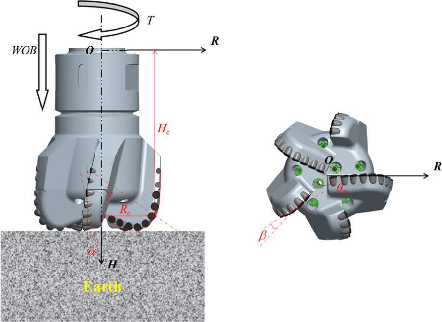
The PDC bit forces and the location and orientation coordinates for cutter.
Development of the mathematical model and solution method
Existing studies have shown that the force and wear conditions of PDC bit are related to the parameters which include ROP, rock type, cutting area, cutting arc length, and so on. Besides, the force and wear conditions are influenced by the teeth mutual interference. Therefore, evolutional process from a single cutter model to the force and wear model of PDC bit is discussed in this section.
Development of the geometric model of a single cutter
For a new PDC bit cutter, the shape usually is a cylinder. After wear and tear, its main typical characteristics are shown in the circle of Figure 2(a). 2 The unworn part looks like a three-quarter moon. Combined with the wear model in the fixed cutter dull grading system 9 made by the International Association of Drilling Contractors (IADC), the model of the worn cutter can be abstracted to the model in Figure 2(b). A Cartesian coordinate system OX4Y4Z4 is built, and origin of coordinates is the center of tooth surface, and axis OZ4 is perpendicular to the wear surface. Then, any point P in a new or worn cutter can be expressed as equation (1). Any point P in circular cutting edge and linear cutting edge can also be expressed as equations (2) and (3), respectively


where (x4, y4, z4) are the coordinates of point P in the Cartesian coordinate system OX4Y4Z4; rp is the distance from point P to axis OY4; t is the distance from point P to tooth surface; rc is the radius of cutter; Hd is the worn height of cuter; φ is the angle between the surface OZ4Y4 and the line linking the point P and coordinate origin O.
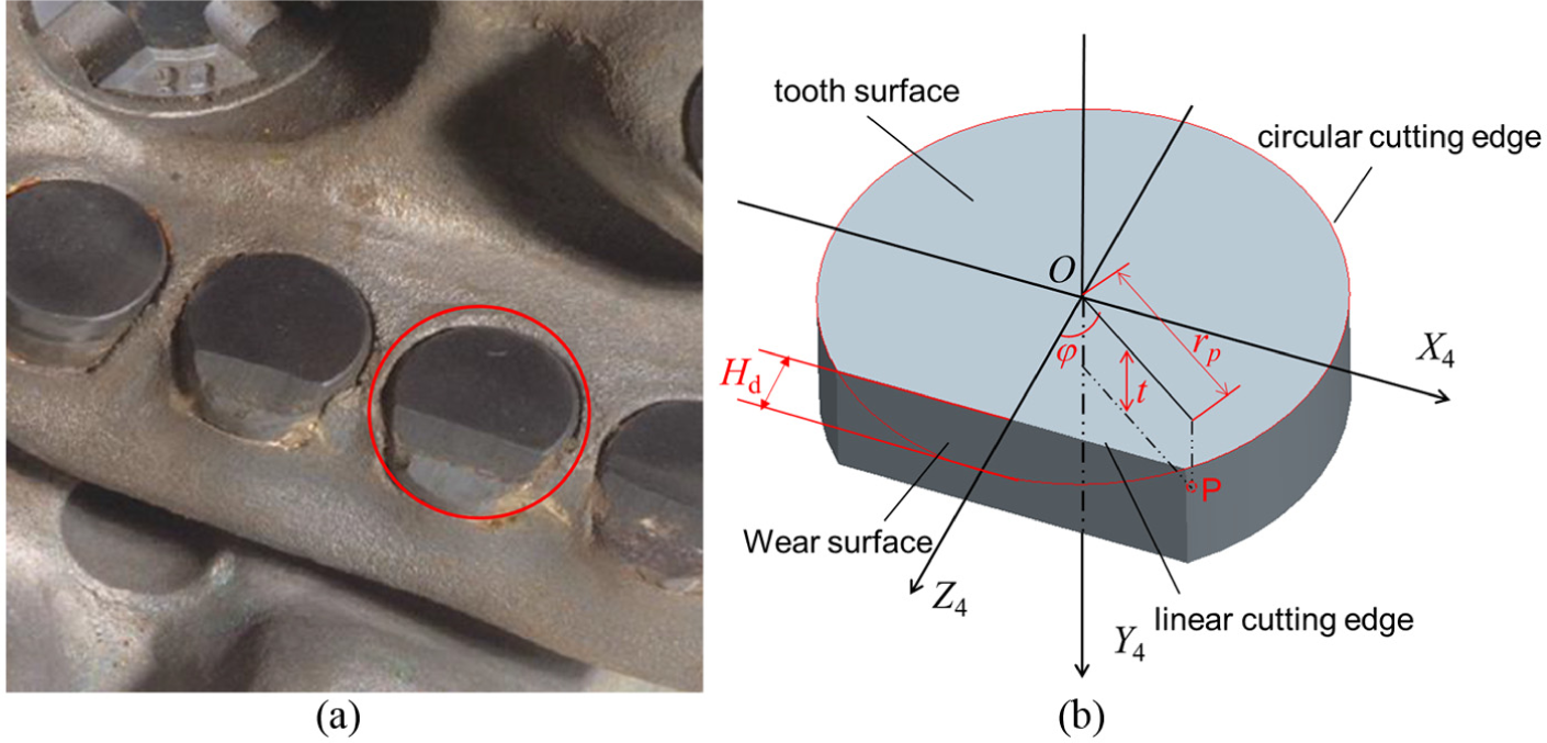
The main wearing characteristics of PDC cutters: (a) the wearing cutters in filed application and (b) the geometric model of wearing cutter.
The cutting edge equations (2) and (3) are important to analyze the cutting parameters. Using the coordinate transformation method, 10 the coordinates (x4, y4, z4) of point P on the cutting edge can be translated to the coordinates (r, h, θ) in the cylindrical coordinate system ORΘH, as shown in equations (4)–(6)


However, equations (4)–(6) cannot represent the real rock breaking model because of the different circumferential positions and rock breaking sequences of each cutter in one PDC bit. Figure 3 shows the method which can obtain the actual cutting parameters of a single cutter. First of all, as shown in Figure 3(a), all of the cutters are abstracted from the PDC bit, and the cutting trajectory composed of cutting edges is easy to obtain from the rock surface. In order to get effective cutting edges of cutters, the plane M and the center axis of the PDC bit are built in Figure 3(b). Let all the cutters rotate around the center axis and project their cutting edges to plane M. Then, the projection of cutting edges can be obtained, and the cutting edge of each cutter can be numbered from inside to outside, as shown in Figure 3(c). 200 cutting edges of different cutters on PDC bits are collected for analysis. The results show that the effective cutting edge of the ith cutter is only related to the four cutting edges which are numberedi−2, i−1, i+1, i+2 and itself as shown in Figure 3(d).

The method to obtain the cutting parameters of a single cutter: (a) the simplified model of PDC cutters with rock, (b) the plane M and the center axis of the PDC bit, (c) projection of each cutting edges, (d) adjacent cutting edges, (e) the real projection of the adjacent cutting edges during drilling, (f) cutting section, and (g) cutting surface and cutting arc.
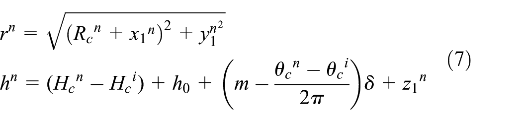
Furthermore, to simulate the real working condition of drilling, a rectilinear motion is added on the rotational motion of all cutters. The rectilinear motion is towards the drilling direction (center axis in Figure 3b). And then, the projection position of the eight cutting edges can be obtained during the PDC bit drilling. In Figure 3(e), the cutting edges which are numbered i − 1′, i + 1′, i′ are the projection of i − 1th, i + 1th, ith cutters through the plane M in the previous cycle. At this point, equations (4)–(6) can be translated into equations (7)–(9). And then, the cutting parameters of each cutter during rock breaking can be solved by these equations. As shown in Figure 3(f), the section surrounded by the effective cutting edges is called cutting section. Cutting volume of single cutter can be obtained by rotation around the center axis of the cutting section. The cutting surface and cutting arc (Figure 4 (g)) can be obtained by data transformation of the cutting section and the ith cutting edge (Figure 3 (f)), and the detailed data transformation is introduced in the block 11 in Figure 7. So far, the three important cutting parameters, cutting surface, cutting arc, and cutting section, have been obtained. Cutting surface and cutting arc are closely related to the force of PDC cutter, because they are the real part to break rock. Cutting section determines the cutting volume


The main parameters tested in the cutting experiment: (a) the force model of single cutter, (b) standard cutting surface, and (c) ordinary cutting surface.
In equations (7)–(9), δ is penetration per revolution (PPR) of PDC bit; n represents the cutting edges number, and Xn represents the parameters X of the nth cutting edge (X can be r, h, x1, etc.). when n = i − 2, i − 1, I, i + 1 or i + 2, m = 1; when n = i − 1′, i + 1′ or i′, PDC cutters are in the previous drilling cycle, and m is equal to 0 at this time; h0 is the height Hc of the ith cutter, when the ith cutter is through the plane M in previous cycle.
The force and wear model of PDC cutter
According to the results of the cutting experiment of single cutter, 5 the cutter force model can be expressed as follows


In equations (10) and (11), d is the cutter diameter; K is the drillability grade of rock; A represents the area of the cutting surface; Ft is the tangential force and Fa is the axis force as shown in Figure 4(a); l represents the real length of cutting arc during drilling as shown in Figure 4(c); in Figure 4(b), ld represents the equivalent arc length when the area of ordinary cutting surface is equal to the area of standard cutting surface. In addition, the TOB, WOB, and Fs of PDC bit can be obtained by the resolution and composition of Fa and Ft.
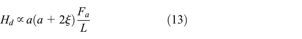
Ideally, the wearing height Hd can be given in equation (12) because of the one-to-one correspondence between Hd and the wearing volume Q 6

where ω is a physical quantity reflected the wear strength of cutter, a is the width of the contact surface between cutter and rock, ξ is the distance from centroid of cutting section to the center axis, µ is the frictional coefficient between cutter and rock, N is the revolving speed, and tc is the total time of breaking rock.
The parameters ω, µ, N, and tc will not change for different cutters when the cutters are on the same PDC bit. At this point, equation (12) can be translated into equation (13). Set Hd of the ith cutter as

Numerical solution method for the key parameters
By the above analysis, the cutting surface and cutting arc are the connecting link between the geometric model and the force model of cutter. Besides, the length of cutting arc l and the area of cutting surface A are most difficult to obtain in all of the above parameters. At the same time, the problem that how to calculate the parameters l and A of the worn cutter has not been reported. Therefore, the method to obtain cutting arc length l and cutting surface area A of PDC cutters is discussed in the next section.
Numerical solution method
In order to obtain the parameters l and A, the cutting section is discussed first. In Figure 2(b), when φ is equal to zero, the corresponding point named zero point on the cutting edge is a key point. The line (overlap with axis OZ4) linking the zero point and coordinate origin O is perpendicular to the rock surface. Therefore, the zero point must be in contact with the rock surface, and the cutting edge near the zero point must be also in contact with rock. Then, the above argument is checked by a large number of analyses for the cutting sections. As shown in Figure 5, they are cutting sections of different worn and unworn cutters. It is obvious that all of the zero points are on the effective cutting edges which are in contact with rock surface.

The zero point on cutting edge.
So far, a new method named zero point traversal (ZPT) method used to obtain the parameters l and A is proposed. Figure 6 shows the traversal path of a worn tooth. The shadowed region is cutting section and the shadowed edges are the effective cutting edges of cutters. The information of each cutting edge can be determined by the bidirectional traversal from zero point to traversal termination point. Then, cutting section area, cutting arc length, cutting surface area, and so on can be gotten gradually. Besides, the method is compiled to MATLAB code.
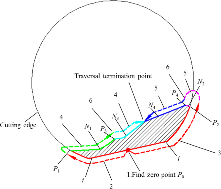
The traversal path of a worn tooth.
Figure 7 shows the detailed calculated process for ZPT method. The block numbers 1–6 correspond to the sequence numbers 1–6 in Figure 6. The first step in this process is to find the zero point P0 of the ith cutting edge (in block 1). Set n equal to i, and φ equal to zero in equations (7)–(9). Then, the coordinate value (r, h) of zero point P0 can be obtained by equation 7.
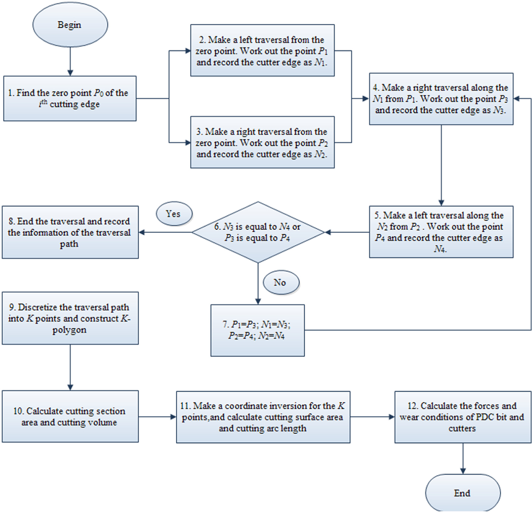
Flowchart for ZPT method.
In the following steps, make a traversal along the ith cutting edge from zero point P0 to left. Work out the point P1 which is the first intersection point of the ith cutting edge and the rest of cutter edges. And record the cutter edge (exclude the ith cutting edge but include point P1) as N1 (in block 2).
In the meantime, make a traversal along the ith cutting edge from zero point P0 to right. Work out the point P2 which is the first intersection point of the ith cutting edge and the rest of cutter edges. And record the cutter edge (exclude the ith cutting edge but include point P2) as N2 (in block 3).
One other thing to note is that all of cutting edges appeared in Figure 7 are some of the eight cutting edges which are numbered i − 2, i − 1, i, i + 1, i + 2, i − 1′, i′ and i + 1′.
Next, make a traversal along the cutting edge N1 from point P1 to right. Work out the point P3 which is the first intersection point of the cutting edge N1 and the rest of cutter edges (exclude the ith cutting edge). In the meantime, record the cutter edge (exclude the cutting edge N1 but include point P3) as N3 (in block 4). Then, make a traversal along the cutting edge N2 from point P2 to left. Work out the point P4 which is the first intersection point of the cutting edge N2 and the rest of cutter edges (exclude the ith cutting edge). In the meantime, record the cutter edge (exclude the cutting edge N2 but include point P4) as N4 (in block 5).
What follow is to judge the N3 whether equal to N4, and the P3 whether equal to P4 (in block 6). If N3 ≠ N4 and P3 ≠ P4, replace P3, N3, P4, and N4 with P1, N1, P2, and N2, respectively (in block 7), and then return to block 4. If N3 is equal to N4 or P3 equal to P4, end the traversal, and record the data of the whole traversal path (in block 8).
After the traversal path is obtained, we discretize the traversal path into K points and construct K-polygon, and figure out the coordinate values [xi, yi] (i = 1, 2,&, K) of the K points in the plane M (in block 9). Then, the cutting section area AS and cutting volume V can be calculated by equations (15) and (16), respectively (in block 10)


where RS is the centroid coordinates of the cutting section.
In the next step (in block 11), make a coordinate inversion for the points [xi, yi], P1 and P2 from the cylindrical coordinate system ORΘH of PDC bit (Figure 1) to the Cartesian coordinate system OX4Y4Z4 of PDC cutter (Figure 2(b)), and then, record the coordinate values as [Xi, Yi] (i = 1, 2,&, K), X1 and X2, respectively. Substitute [Xi, Yi] for [xi, yi] in equation (15), and then, the cutting surface area A can be obtained by equation (15); the cutting arc length L can be obtained by multiplying cutter radius and central angle (radian) of the cutting arc.
Next, the force of a single cutter can be obtained by equation (10). The WOB, TOB, and transverse force Fs of PDC bit can be solved by equation (18). The wear trend can be predicted by equation (14) (in block 12)
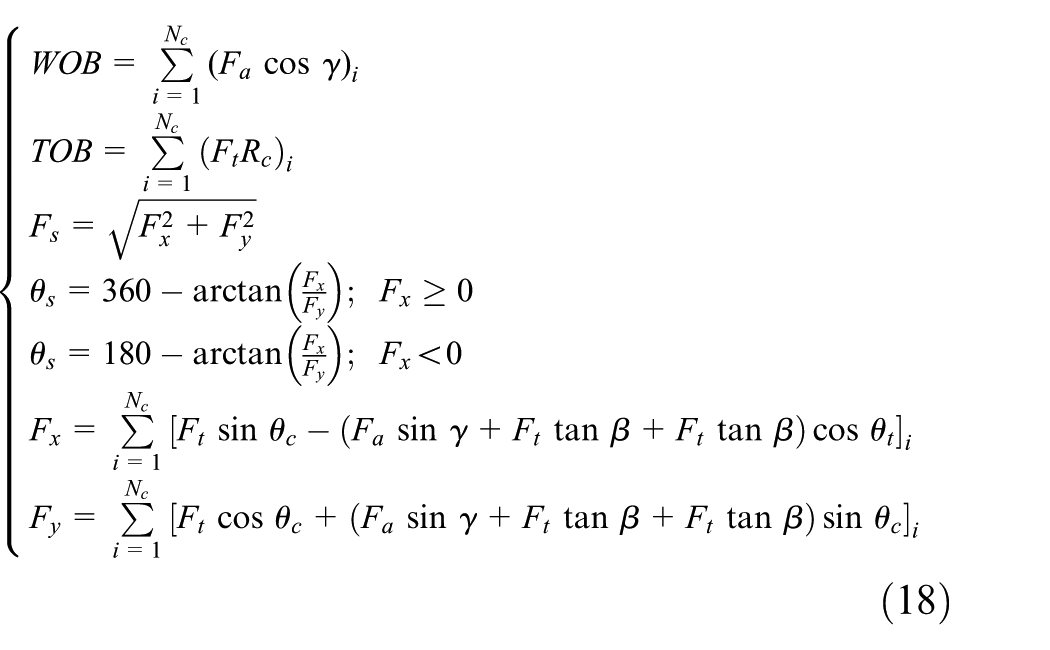
where Nc is the total number of cutters in PDC bit and θs represents the direction of Fs.
Comparison and validation
The results of the cutting parameters with different methods
So far, solving objects of the existing methods are the unworn cutters. In order to verify the correctness of the ZPT and compare with the existing methods, the cutting parameters of unworn cutters are calculated first. At this point, the parameter Hd of all of the above equations is equal to zero.
An existing method named digitalization technology of PDC bit drilling 11 is adopted to calculate the cutting parameters of a PDC bit which has 32 teeth. Figures 8 and 9 show the results of cutting arc length and cutting volume calculated by ZPT and digitalization technology of PDC bit drilling, respectively. Compared with the digitalization technology method, the relative error of ZPT is 1.13% when the cutting arc length is calculated in Figure 8, and the relative error is 2.00% when the cutting volume is calculated in Figure 9. Therefore, ZPT can be utilized to calculate the cutting parameters of unworn cutters.
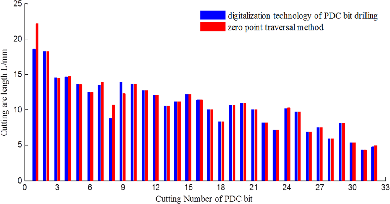
The results of cutting arc length of unworn cutters when the penetration per revolution (PPR) is 4 mm.

The results of cutting volume of unworn cutters when the PPR is 4 mm.
Furthermore, Pro/Engineering is used to draw the cutting section of worn cutters and measure the area. Meanwhile, ZPT is also used to help determine the cutting section area of the same cutters. The results of the cutting section area and shape are shown in Table 1. The cutting section shapes of two methods are same, and the average relative error of the two methods is 0.035%. Therefore, ZPT can be used to calculate the cutting parameters of worn cutters.
The shape and area of cutting section of worn tooth when PPR is 4 mm, and back rake angle α and side rake angle β are equal to zero.

ZPT: zero point traversal.
Comparison of PDC bit forces
According to the actual drilling records of A type PDC bit in the KL20-1-1 well of the Bohai oilfield in China, the average PPR is 4 mm, and the drillability grade of rock K is equal to 3.2. 5 Combined with the ZPT and the above force model, the force analysis is performed for the A type PDC bit. Compared with the actual drilling parameters in the drilling records, Table 2 is obtained. The average relative errors of the WOB and TOB are 0.95% and 4.67%, respectively. It shows that the computational process is inerrant and the methods can apply in practical engineering.
The comparison of the forces of A type PDC bit.

Wear trend predict
The wear trend can be predicted based on the wear and force model of PDC cutter. Figure 10(a) shows the wear trend prediction of PDC bit cutters when the average PPR is 4 mm. The wear heights of cutters increase with the drilling time. While with the increasing of cutter number, the wear heights increase first and then decrease. The 7th–12th cutters on the nose of PDC profile (Figure 10(b)) have the highest wear heights. This wear tendency is compliant with the wear status of the PDC bit in field application as shown in Figure 10(c). Therefore, the predicted method of wear trend based on ZPT is feasible, and it can quantify the relative wear degree of each cutter at different times.
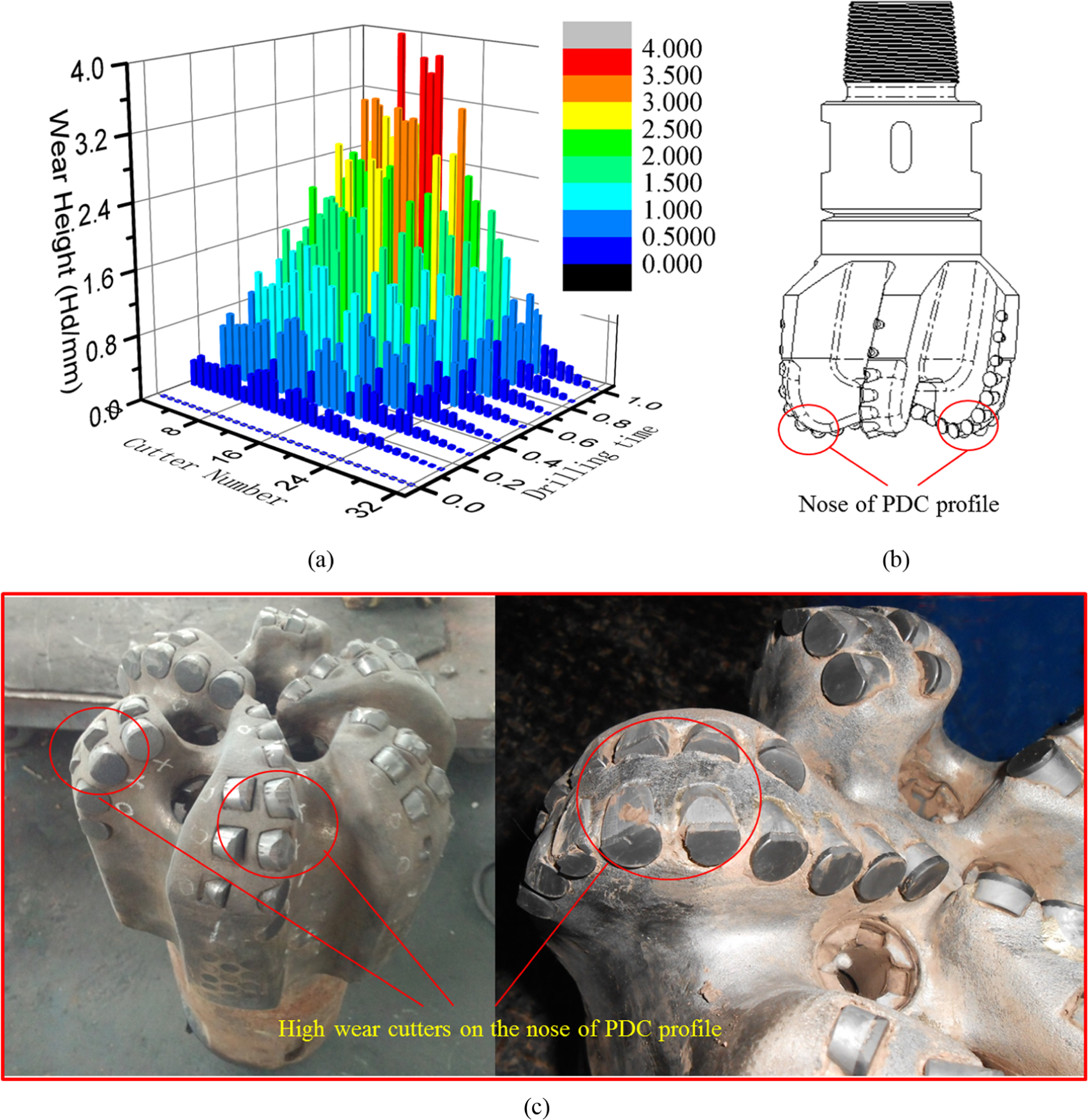
Wear trend prediction of each cutter in one PDC bit: (a) the result of wear trend prediction, (b) the nose of PDC profile, and (c) high wear cutters on the nose of PDC profile.
Mechanical properties analysis of PDC bit under different conditions
Effects of wearing degree on cutting parameters and forces of cutters
In this section, the cutting parameters and mechanical properties of the cutters no. 10–20 of a PDC bit are discussed under different wearing conditions. The drillability grade of rock is 3, and the PPR is 4 mm, and the wearing heights of the cutters are 0, 0.5, 1, 2, 2.5, and 3 mm. The above cutters and drilling parameters can reflect the effects of wearing degree and mutual interference of cutters on cutting parameters and forces since the cutters are adjacent.
Effects of wearing degree on cutting arc length and forces of cutters
In Figure 11, when the PPR is contact and wear loss increases, all of the cutting arc length increase with nonlinear rule. The total arc length increases from 123.7 to 194.1 mm and the growth rate is 56.9%. According to equations (10) and (18), set all parameters as constants but the wear loss and arc length, then equation (10) can be transformed into
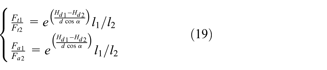
where Ft1 and Ft2 are the tangential force under two different wearing status; Fa1 and Fa2 are the axis force under two different wearing status; Hd1, Hd2 and l1, l2 are the wear heights and cutters arc lengths under two different wearing status, respectively.
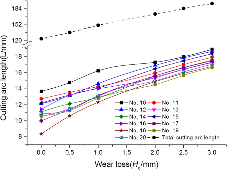
Cutting arc length trend with wear loss increase when PPR is 4 mm.
If the status of wear loss 0 and 3 mm is only considered, the force growth rate Rf can be expressed in equation (20) since Hd1 and Hd2 are constants

The average force growth rate Rf t of the total cutters is

If these 11 cutters can represent the PDC bit, WOB and TOB of the PDC bit need to increase
Effects of wearing degree on cutting section area, cutting volume and forces of cutters
In Figure 12, the variation trends of cutting section area AS and cutting volume V are similar because of the linear relationship (equation (16)) between AS and V. The total cutters section area and volume are almost a constant. That is because when rock breaking efficiency (PPR) is fixed, the rock breaking volume of PDC bit is not changed. Besides, the maximum change rates are 22.3% and 24.25% for the cutting section area and the cutting volume of a single cutter, respectively. The change rate is small compared with the growth rate of cutting arc length.
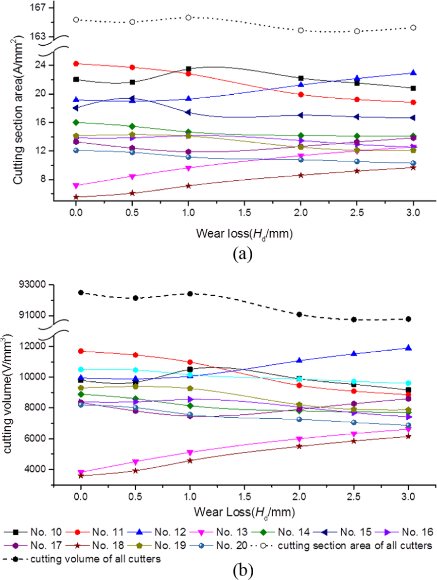
Cutting section and cutting volume trend with wear loss increase when PPR is 4 mm: (a) the changing trend of cutting section area and (b) the changing trend of cutting volume.
According to eq. (10), set all cutting parameters are constants but the cutting section areas for each cutter, only consider the status when wear loss is 0 and 3 mm, then equation (22) can be obtained by the same method in section “Effects of wearing degree on cutting arc length”

According to eq. (22), the force growth rate is (A1/A2)0.7564e3/(dcosα) for a single cutter if the cutting section area is only considered. Under a consistent drilling efficiency (PPR), the forces of some cutters in PDC bit increase but some decrease with the wear loss of cutter. For instance, the force of No.11 cutter (Figure 12) decreases of 2.2%, because (A1/A2)0.7564e3/(dcosα) is equal to 0.978; the force of No.12 cutter (Figure 12) increases of 35.5%, because (A1/A2)0.7564e3/(dcosα) is equal to 1.355. At the same time, the WOB and TOB of the PDC bit increase slowly (compare with equation (21)) if only the cutting section area changes. Finally, the Rf2 can be simplified to
Effects of wearing degree on force
With the wear loss increase, the transverse force, torque, and axial force of cutters increase at the average ratio of 2.1844, 2.1656, and 2.1302, respectively. In general, the directions of the torque of all cutters are consistent, and the axial forces are also consistent. So the change trend of axial forces and torque of the cutters (Figure 13) can represent the forces of PDC bit. At this point, the WOB and TOB can be expressed based on equations (21) and (22). Therefore, PDC forces are closely connected with the change of cutting arc length


The change trends of forces for cutters.
On the other hand, transverse forces of the PDC bit cannot be predicted by the simple development of equations, because the directions of transverse forces are different for the cutters. In Figure 14, the sizes and directions of transverse forces under different wearing conditions are displayed in the two-dimensional polar coordinates Oθρ. The linking line connected the vertex P of polygonal and the original point O in Figure 14 represents the transverse force. The sizes of transverse forces increase with the wear loss, while the direction of transverse forces is almost unchanged when the wear loss increases. After the calculation of total transverse force of PDC bit, the direction of transverse force fluctuates in a small range (<8°), but the growth rate of size is 1.8536.
The sizes and directions of transverse forces under different wearing conditions.
Effects of PPR on cutting parameters and forces of cutters
In this section, the cutting parameters and mechanical properties of the cutters no. 10–20 of a PDC bit are discussed under different PPR conditions. To the best of our knowledge, the range of drillability grade of rock is 0–6 suitable for PDC bit drilling. In order to represent the generality of PDC bits, the drillability grade of rock is set to 3. The PPR of the cutters is set to 1, 1.5, 2, 2.5, 3, 3.5, 4, 4.5, 5, 6, 7, 8, 9, and 9.5 mm. The range [1, 9.5] can cover almost all of the drilling situations of PDC bits
In Figure 15, all the cutters have a same wear height of 2 mm. The cutting parameters and forces increase with the PPR in approximately linear rule.
The changing trend of cutting parameters and forces with difficult PPR: (a) the changing trend of axial force, (b) the changing trend of torque, (c) the changing trend of transverse force, (d) the changing trend of cutting arc length, and (e) the changing trend of cutting section.
Compared with the effect of wearing degree on cutting parameters, the trend of cutting arc length changes from nonlinear (Figure 11) to approximate linear (Figure 15(d)), and the total cutting section area changes from a constant (Figure 12) to linear increase (Figure 15(e)). In addition, the trends of forces of the cutters (Figure 15(a)–(c)) increase with the PPR in approximately linear rule.
Discussion
In this article, the mathematical models of worn and unworn cutters are built in the cylindrical coordinate system ORΘH and the Cartesian coordinate system OX4Y4Z4. Then, a numerical analysis method named ZPT method used to solve the cutting parameters such as cutting arc length, cutting section area, cutting volume, and so on is proposed. Thus, the linking relationship is built between geometric model and force-wear model of cutter. Then, mechanical properties analysis of PDC bit under different wear conditions and different PPRs are carried out based on the geometric model and force-wear model of cutter and ZPT method.
So far, the force and wear analysis system of PDC bit and cutters is not perfect because it lacks an important link that how to get the complex cutting parameters of worn cutters under the mutual interference of adjacent cutters. For instance, an integrated mechanical model of a single cutter is under construction by an experimental research, 5 but the method is not applicable to solve the forces of the worn cutters in one PDC bit until the complex cutting parameters can be obtained. Up to now, however, most of the solving methods11–15 for cutting parameters are aimed at unworn cutters. In other words, the cutting parameters of the worn cutters cannot be obtained if the existing methods are not improved. In addition, there are some wear models of PDC bit and cutters;6,7 however, they cannot be used to calculate the wear state since they lack the cutting parameters, and the relationship between cutters and PDC bit cannot be obtained since the PDC bit is viewed as a whole. The above problems are resolved by the development of the mathematical model and the ZPT method. When the complex cutting parameters are gotten by the mathematical model and the ZPT method, the linking relationship between geometric model and force model of cutters, the force relationship between cutters and PDC bit all can be obtained. Then, the force and wear analysis system of PDC bit and cutters become coherent and integrated.
With the above new methods, according to the drilling parameters, rock type and cutter layout parameters, the mechanical properties of PDC bit can be analyzed. In general, controlling the drilling parameters can change the force status of PDC bit. However, as mentioned in the above analysis in section “Effects of PPR on cutting parameters and forces of cutters”, the effect of drilling parameters (PPR) on the mechanical properties of PDC bit and cutters is very limited. Each type force of cutters of a PDC bit almost increases with PPR by the same ratio (Figure 15(a)–(c)). Therefore, the drilling parameters can change the force status of the whole PDC bit easily, while the relative forces status of cutters is hard to change.
Under a constant PPR, the main characteristic is that the cutting section areas of cutters change very little, and the forces status is closely related to the wear heights and cutting arc lengths. This characteristic has been confirmed by numerous cases. For instance, a wear trend of a PDC bit with 16 cutters is carried out in Figure 16. The cutting section area is almost a constant; the forces increase with the cutting arc lengths (except cutters no. 1, 2, and 3) and the wear loss. Therefore, how to control the wear trend of each cutter and design the cutting arc length is the most important thing to improve the properties of PDC bit.

The wear trend prediction of cutters of a PDC bit.
It is well known that the main content of PDC bit design is cutter layout design. One of the deal conditions of the cutter layout is equal wear loss of cutters during PDC bit drilling. However, the equal wear status is almost impossible because of the complex cutting parameters and the hard-to-find changing rule of layout parameters on cutting parameters. But, we can keep the wear heights of cutters of a PDC bit as equal as possible by the design of cutters layout parameters. As shown in Figure 17, the wearing otherness of cutters is reduced by optimization of cutting arc length and the design test of the cutter layout parameters.

The wear trends of difficult cutters on a PDC bit with difficult cutters layout: (a) the wear trend of the PDC bit with the original cutter layout and (b) the wear trend of the PDC bit with the optimized cutter layout.
Finally, it should be noted that the new models and methods are focused on homogeneous formation, constant PPR, and the PDC bit whose principal failure mode is cutter wear (Figure 10(c)). The new methods cannot be applied in the harsh condition that the degree of axial vibration of PDC bit is large, or the main failure types of PDC bits are not cutter wear but the fracture failure, spalling failure, and so on in the process of drilling some hard and inhomogeneous formations.
Conclusion and further research
A new numerical method named ZPT method is proposed to solve the cutting parameters of cutters based on the development of the geometric model of wear and unworn cutters. It is an intimate bond with geometric model and force model of cutters. It can be utilized to obtain the force conditions of cutters, predict the wear trends of PDC bit, and analyze whether the cutter layout design is reasonable for a PDC bit.
The effect of PPR on the mechanical properties of PDC bit and cutters is very limited. Each type force of cutters almost increases with PPR in linear rule by the same ratio. Under a constant PPR, the cutting section area virtually keeps a constant with the increase of wearing degree; the direction of the transverse force almost keeps unchanged. The forces of cutters increase with their cutting arc lengths and wear loss.
Based on the ZPT method and the mechanical properties, the cutter layout design can be carried out by the parameters adjustment of cutter layout to make the cutting arc length has a reasonable value. It can receive a better effect as shown in Figure (16). However, there are six cutter layout parameters of a single cutter. For a PDC bit with 20 cutters, it has 120 cutter layout parameters. It is quite complex to research the relationship between cutting parameters and each cutter layout parameter. How to keep wear loss of cutters as equal as possible by the optimization of cutter layout parameters is an important research direction.
Footnotes
Academic Editor: Jianqiao Ye
Declaration of conflicting interests
The author(s) declared no potential conflicts of interest with respect to the research, authorship, and/or publication of this article.
Funding
The author(s) received no financial support for the research, authorship, and/or publication of this article.