
Abstract
The performance of aerostatic spindle is highly affected by the fluid–structure interaction effect between solid structure and air film. In working condition, the viscous heat generated by air film also influences the spindle performance greatly. In this article, the structure deformation induced by pressurized air film and viscous heat is investigated based on a multi-physics coupling model. The simulation results indicate that the structure deformation could lower the load-carrying capacity of air bearing. The reliability of proposed model is verified by experiments.
Keywords
Introduction
Aerostatic spindle is widely used in the precision equipments, for example, ultra-precision machine tool, precision turntable, due to its unique advantages of high speed, negligible friction, and excellent rotation accuracy.1–3 The aerostatic spindle is made up of the structure components and the fluid film. The basic working principle of the aerostatic spindle is that the externally pressurized air forms a thin film in the clearance between shaft and shaft sleeve after throttling action of restrictor, and the air film forces oppose the external load and maintain the separation of the surfaces of shaft and shaft sleeve.4–6 The aerostatic spindle is designed hope to with high stability and high precision, while there are too many factors affect the performance of the aerostatic spindle, such as the fluid–structure interaction effect between the structure components and the fluid film, the thermal generated in high rotation speed. All of those factors will reduce the accuracy of the aerostatic spindle.
Numerous researchers carried out the study of aerostatic spindle. Du et al. 7 improved the load capacity and stiffness of an aerostatic spindle by optimizing the structural parameters of pressure-equalizing grooves such as the length, depth, number, and location. Cheng et al. 8 investigated the performance of high-speed spindle aerostatic bearings by considering the volume flow rate change of a journal bearing operated at different rotational velocities. Akhondzadeh and Vahdati9,10 carried out the studied of the relationship between the number and size of air pockets in air spindles and nanomachining vibrations and optimized the parameters of the pocket in aerostatic bearings. Li and Ding 11 investigated the influence of geometrical parameters on bearing performance and pointed out that the orifice length has significant influence on bearing performance when the orifice diameter is excessively small.
Most of the previous studies were focused on the structural parameters design of optimization of the aerostatic bearing, while the aerostatic spindle is working in coupling fields, known as mechanical–thermal–fluidic–electromagnetic fields. Thus, the multi-physics nature should be studied to improve the performance of the aerostatic spindle. Recently, there are also some researchers pay attentions on the multi-physics coupling analysis of an aerostatic spindle. Gao et al. 12 presented a multi-physics integrated modeling using the computational fluid dynamics (CFD)–finite element analysis (FEA) integrated approach for design and analysis of the high-speed aerostatic spindle, including thermal, electromagnetic, mechanical, and fluidic analysis models. But, the structural deformation induced by pressurized air film is ignored in their simulation model. Lu et al. 13 presented a new design method of aerostatic spindle based on the fluid–structure interaction method. In their study, the changes of bearing clearance caused by the structure deformation under high pressure fluid film were considered, and the static performances of the bearing were obtained. The relationship between multi-physics coupling data within the design and analysis of the direct-drive aerostatic slideway was investigated by Li et al., 14 and a multi-physics simulation environment was essential to realize the seamless integrated design and analysis of aerostatic slideway at a nanometric level of accuracy. In this article, a multi-physics model is established, and a calculation based on fluid–structure–heat interaction method is carried out to investigate the fluid–structure interaction and thermal effect of aerostatic bearing.
Multi-physics modeling of an aerostatic spindle
Parameters of the aerostatic spindle
The configuration of a self-developed aerostatic bearing is demonstrated in Figure 1(a). As can be seen from Figure 1(a), the air bearing is composed of radial bearing and thrust bearing. Upper thrust plate and lower thrust plate are connected to shaft with bolts. With the support of pressurized gas film, the shaft can rotate with almost no friction.

Configuration of aerostatic bearing: (a) structure of an aerostatic bearing and (b) configuration of aerostatic thrust bearing.
The configuration of thrust bearing is demonstrated in Figure 1(b). Detail parameters of orifice are presented in Table 1. Where h is the bearing clearance, D and D2 are the inner diameter and outer diameter of air film, respectively. There are six orifices equally spaced on a circumference of diameter D1. The details of these parameters are listed in Table 1.
Thrust bearing parameters.

Two types of restrictors are wildly used in aerostatic bearing: pocketed orifice-type restrictor and inherently orifice-type restrictor. Generally, pocketed orifice-type restrictor is better than inherently orifice-type restrictor in terms of static stiffness and load-carrying capacity. The restrictor area of pocketed orifice-type restrictor is supposed to be the minimum area of the air channel, which means that the parameters of the orifice should satisfy d2π/4 < (h1 + h)πd and d2π/4 < πd1h at the same time (h1 is the depth of chamber and d1 is the chamber diameter). In addition, to ensure that pneumatic hammer is avoid, the ratio of pocket volume to clearance volume should be less than 0.1 for air thrust bearing. It sets up a restriction for the design of chamber depth.
However, inherently orifice-type restrictor is tend to more steady than pocketed orifice-type restrictor, because many researches indicate that there are vortices inside the chamber. Therefore, inherently orifice-type restrictor is adopted in this article.
Modeling of the aerostatic spindle
Generally, two methods can be employed to solve fluid–structure interaction (FSI) problems: direct coupling method and separation method. The direct coupling method calculates the governing equations of fluid field and solid structure simultaneously by coupling these equations into a matrix equation, by which more accurate results can be acquired. However, it is rather time-consuming, which is seldom employed in practices. The separation method is more frequently adopted as it shows many advantages, such as time-saving and decreasing requirement of computer. Therefore, the separation method is employed in this article.
Figure 2 demonstrates the simulation process of separation method adopted in this article. The simulation process starts from the CFD analysis. The CFD model consists of the fluid field of air film and the solid structure of shaft, and the viscous heat generated by air film and the conjugate heat transfer between air film and shaft are considered in CFD analysis. So, the pressure and temperature distribution of air film and temperature field of shaft can be obtained in this step. Then, the CFD analysis results are transferred to the FEA model. The pressure air film is applied on the fluid–structure interfaces of thrust plates as force load, and the temperature of air film is applied as temperature load. In this step, the deformation caused by viscous heat of air film and air film force can be acquired. Next, the deformation of shaft is transferred back to the CFD model, and the CFD mesh is updated based on the deformation of shaft correspondingly. Then, the CFD analysis is carried out again with new computation mesh, and the redistributed pressure of air film can be acquired. This is a data exchange cycle of the simulation process. The above process is carried out repeatedly until there is no significant change in the deformation of shaft and the pressure distribution of air film; the simulation process is finished.

Flowchart of separation method.
Figure 3 shows the computation mesh of shaft and air films. The grid number of shaft is 2858, and the grid number of air films is 552560. The structure deformation is calculated by finite element software ANSYS, and the fluid field of air film is solved by CFD software Fluent. To save calculation time, a one-sixth model is employed to increase the calculation speed. The boundary conditions are also demonstrated as shown in Figure 3. Inlet is the entrance of the pressured air, while the outlet is the exit of pressured air. At the periodic boundary surfaces, the surfaces have same mesh and nodes distribution, and the velocity, temperature and pressure of each nodes are same.
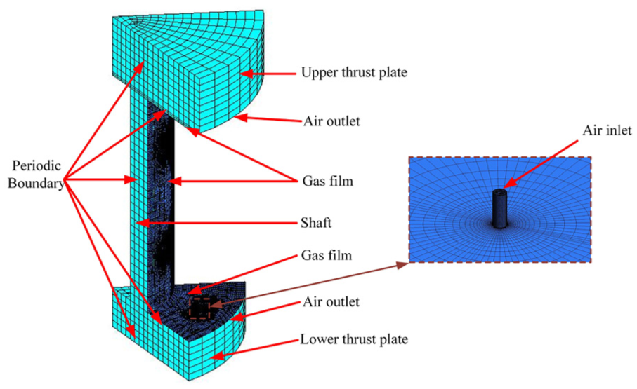
One-sixth model of gas film and solid structure.
The main calculation parameters of boundary conditions are listed in Table 2. The supply pressure of air film is 0.5 MPa, and the inlet temperature of air is 293.15 K. The atmospheric pressure is applied on the outlet of air film. The ambient temperature is set at 293.15 K. The rotational speed of shaft is 1000 r/min. The viscous heating of air film is calculated by the solver of CFD software Fluent, and the convection heat transfer between air film and shaft is calculated directly based on the solution in the adjacent cells of the fluid–structure interface. The convection heat transfer between the outside surfaces of shaft and the ambient temperature is considered as forced conviction, and it is simulated by constant heat transfer coefficient of 15 W/m2 K. The ideal-air model is adopted in this analysis to take the compressibility of air into accountant. Its specific heat is 1006.43 J/kg K, and its thermal conductivity is 0.0242 W/m K. The dynamic viscosity µ of ideal-air is calculated with the Sutherland equation as shown in the following

where µ* = 1.716 × 10⁻⁵ Pa s, S = 110.56 K, T* =273.11 K. The material of shaft is steel. Its density is 8030 kg/m3, specific heat is 502.48 J/kg K, and thermal conductivity is 16.27 W/m k.
The main calculation parameters of boundary condition.

Results discussion
The calculation results are visualized in Figure 4. Figure 4(a) shows the pressure distribution on FSI interface. It indicates that the pressure near the orifice is rather high and the pressure decreases from orifice to outlet gradually.

Simulation result of air film and structure: (a) pressure distribution of air film, (b) temperature distribution of air film, (c) total deformation of structure, and (d) pressure distribution of air film.
The temperature distribution of air film is demonstrated in Figure 4(b). The temperature of different points is almost equal as the rotate speed is low. Only near the exit of orifice, the temperature is much lower than average level. Figure 4(c) presents the total deformation of structure. Under the pressure of air film and temperature load, the maximum deformation of structure reaches 1.414 µm. It accounts for 11.8% of the thickness of air film, which means that the static character, such as load-carrying capacity and static stuffiness, differs from original design. To clearly depict the load-carrying capacity change caused by structural deformation, the pressure contours of air film before and after structural deformation are compared as shown in Figure 4(d). It shows that the pressure decreases slightly when structural deformation is considered. The CFD numerical calculation results show that the load-carrying capacity of air film declines from 417 to 362 N.
Figure 5 analyzes the deformation of shaft and thrust plates. Seven points are marked with successive letters from A to F in Figure 5(a), and the deformation data along BC, CD, and DE are presented in Figure 5(b)–(d), respectively. The shape of these curves reflects the shape of structure after deformation. Figure 5(c) represents the deformation of shaft. It implies that the shaft is elongated in its axis direction. Furthermore, the elongation amount of shaft first increases and then decreases with the increase of Y coordinate. It means that the elongation amount at the two ends of shaft is larger than the middle of shaft. Figure 5(b) and (d) shows the deformation of thrust plates. It can be seen that both the deformation amount of upper thrust plate and the lower thrust plate increase with the increase of X coordinate. It means that the clearance between thrust plate and shaft sleeve increases due to structure deformation, and the air film thickness is getting thicker along with the increase of X coordinate in the radial direction.
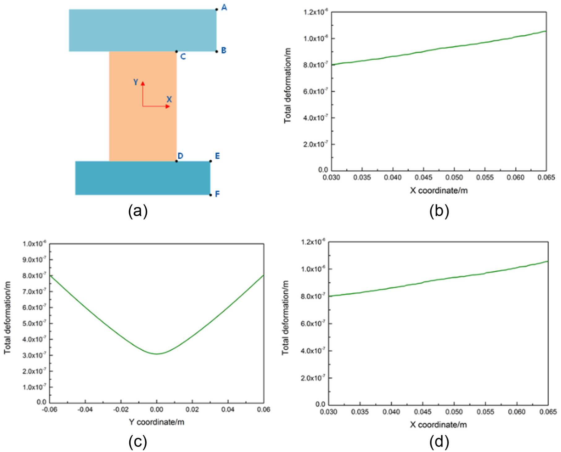
Deformation data statistic: (a) diagram of aerostatic bearing, (b) total deformation along CB, (c) total deformation along CD, and (d) total deformation along DE.
Three kinds of FSI simulations which consider effects of different factors on aerostatic bearing are carried out to investigate the reliability of them. Fluid–structure–heat interaction method, which employed in this article, takes heat and pressure into account to calculate the deformation of structure. FSI method only transfers the pressure data to structure model, while the structure–heat interaction method only considers thermal effect.
The calculation results are compared and contrasted in Table 3. The deformation amount of each marked point acquired by fluid-structure-heat interaction method is larger than that of acquired by other two methods, and it is approximately equal to the sum of the deformation amount calculated by other two methods.
Deformation data of different methods at each marked point.

When aerostatic spindle is working, the thermal deformation induced by air film viscous heat and the deformation caused by air film forces exist simultaneously. Therefore, the fluid–structure–heat interaction method can obtain a more accurate result.
Experiments
To verity the proposed fluid–structure–heat interaction method, the deformation of thrust plate is measured in this section. When measuring the total deformation, the static deformation and thermal deformation are coupled together. So, directly measuring the total deformation is difficult. In this study, they are measured separately. In the working condition of air spindle, no matter the shaft rotates or not, as long as the pressurized air is supplied, the deformation of thrust plate will be induced by air film force. Hence, the static deformation is measured first.
Figure 6 shows the test setup for deformation measuring. A high accuracy displacement sensor with resolution of 10 nm is employed. The experiment apparatus is placed on a marble base to isolate external vibration. Along the radial direction of thrust plate, the displacement of several points with equal interval is measured. During the measuring, the displacement sensor moves along the radial direction of thrust plate, and the corresponding deformation data of each points are recorded as listed in Table 4. From Table 4, it can be seen that the deformation of thrust plate increases along the radial direction of shaft. It indicates that the thrust plate is warped due to the air film force. The largest deformation takes place at the outer edge of thrust plate.
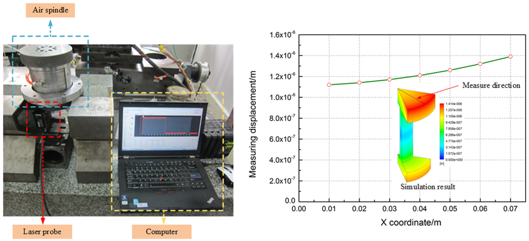
Displacement measurement experiment for aerostatic bearing.
Static deformation test data.

After the static deformation is acquired, the thermal deformation is measured. To eliminate the influence from room temperature changing, the test setup is placed in a temperature-controlled room. During the test process, the temperature amplitude remains in around 1°C. The test process of thermal deformation is described in the following. First, the room temperature is set at 20°C. In addition, to ensure the initial temperature of air-spindle system is 20°C, and the air spindle is placed in the temperature-controlled room for 24 h before testing. Next, the shaft rotates with rotational speed of 1000 r/min until the overall thermal equilibrium of spindle system is reached. Then, the thermal deformation of thrust is measured, and the thermal deformation data of each point are listed in Table 5. From Table 5, it can be seen that the deformation of thrust plate also increases along the radial direction of shaft. And, the largest deformation takes place at the outer edge of thrust plate. The sum of the static deformation and thermal deformation is the total deformation. The test result indicates that the largest deformation of trust plate is 1.4 µm, which agrees well with the calculation.
Thermal deformation test data.

Conclusion
In this article, the structure deformation induced by pressurized air and viscous heat is studied based on fluid–structure–heat interaction method, and experiments are carried out to validate the simulation result. The main conclusions are drawn as follows:
The proposed fluid–structure–heat interaction method can predict the structure deformation accurately, which is verified by experiment.
The structure deformation of thrust plate influences the load-carrying capacity of air bearing greatly. Its deformation should be considered at the design stage of aerostatic spindle.
The fluid–structure–heat interaction method shows better accuracy comparing with FSI method and structure–heat interaction method.
Footnotes
Academic Editor: Mark J Jackson
Declaration of conflicting interests
The author(s) declared no potential conflicts of interest with respect to the research, authorship, and/or publication of this article.
Funding
The author(s) disclosed receipt of the following financial support for the research, authorship, and/or publication of this article: The authors gratefully acknowledge the financial support of the International Science & Technology Cooperation Program of China: Research and Development of High Stiffness Nano-drive Systems of Ultra-precision Machine Tools (2015DFA70630), and the National Natural Science Foundation of China (51505107).