
Abstract
In ultra-precision fly-cutting machining, the aerostatic spindle is the key component, which has significant influence on the machined surface quality. The unbalanced spindle directly affects the machining accuracy. In this article, a prediction model of machining surface topography is proposed which involves the effect of the gas film performance of spindle in microscale. With the Weierstrass function, unstable transient response of the aerostatic spindle system is derived by the motion model of the spindle, which response signal represents the surface profile in the ultra-precision machining. Meanwhile, the experiment is performed with different rotation speed of the spindle. And the effect of the unbalanced aerostatic spindle on the surface generation is discussed in time and frequency domain. The conclusion shows that the similar cyclical surface ripple of the workpiece is independent of the spindle speed, and the rotation speed of the spindle and unbalanced spindle directly affects the machining surface topography. This study is quite meaningful for deeply understanding the influence rule of spindle unbalanced error from the viewpoint of machined surface and vibration frequency.
Introduction
The morphology features of the machined surface are critical factors that affect the quality of manufactured products which is one of the most important considerations for any manufacturer. Lots of factors can affect the machining result of the ultra-precision machine tool, such as mechanical vibration, crystal orientation, physical properties of the material, cutting conditions, and rotation spindle. Mekid and Ogedengbe 1 found that the consistent performance of the machine tool was constrained by the errors built in the machine basis on the account of change in temperature and cutting forces. Cao et al. 2 pointed out that any slight mass unbalance could induce vibrations which might result in dimension errors and poor surface finish of fabricated parts. Sun et al. 3 studied the formation of chips during dry turning of Ti6Al4V alloy and found that the cutting forces and chip formation in machining of titanium alloys were related to cutting speed, feed rate, and cutting depth. Munoa et al. 4 pointed out that the appearance of chatter on machine tools was disastrous since it prevented from obtaining the required surface finishes and decreased the life of tools and mechanical components. Cao et al. 5 pointed out that the chatter stability of machine tool was dependent on the dynamic behavior of spindle systems and presented an alternative method to predict the chatter stability lobes of high-speed milling with consideration of speed-varying spindle dynamics. Uddin et al. 6 proposed and discussed the effect of crystallographic orientation on wear of diamond tools. Furthermore, the relationship between tool wear and surface roughness was discussed. Chi and Lee 7 found that the material-induced vibration caused by the variation of crystallographic orientation was one of the major factors contributing to the generation of surface roughness. Wu et al. 8 used an experimental method to prove and measure the existence of the spindle axial drift at the machining process, and the influence of the spindle drift error on the machined surface was further studied. Wang et al. 9 presented a theoretical and experimental investigation into the effect of the workpiece material on surface roughness in the ultra-precision milling process and proposed a new method to characterize material-induced surface roughness on the raster-milled surface. Chan et al. 10 found that the surface roughness of the cutting surface was affected by both the process factors and material factors. Kong et al. 11 investigated the effect of different factors on surface generation in ultra-precision raster milling and found that machining parameters, tool geometry, cutting strategy, and tool wear were the critical factors for achieving super mirror finish surfaces. Cheng et al. 12 built the theoretical model for the prediction of surface roughness taking into account different cutting conditions and cutting strategies. Hung et al. 13 evaluated the machining stability of a vertical milling system under the interactive influence of the spindle unit and the machine frame structure. Marsh et al. 14 presented a model to accurately predict the workpiece flatness obtained in a series of cutting trials carried out with a high-speed fly-cutting spindle. Cao et al. 15 presented an adaptive approach for the separation of unbalance vibration in air bearing spindles. And the effects of unbalance mass on the vibration responses of the air bearing spindle were studied in detail with the recovered signals. Zhang and To 16 proposed nonlinear equations for spindle vibration of the ultra-precision raster milling in detail which more accurately represented the spindle vibration and were directly integrated with a surface generation model to study its special effects on surface generation. Chen et al. 17 pointed out that the frequency characteristics of the ultra-precision spindle mainly affected the frequency domain error of the machined surface and obtained the amplitude change law of these main spindle errors through the frequency analysis. Chen et al. 18 pointed out that tool geometry, material-related factors, and original surface characteristics might have some influence on the error frequency components on the machined surface as well as the error magnitude. Dou et al. 19 pointed out that chatter was a harmful machining vibration that occurred between the workpiece and the cutting tool, usually resulting in irregular flaw streaks on the finished surface and severe tool wear, and constructed the analytical model of a spindle system to predict chatter.
The spindle of the ultra-precision machine tool is usually aerostatic or hydrostatic, which is more complex than the fluid movement in the bearings. In particular, the gas fluctuation occurs easily due to the low air viscosity in aerostatic spindle. Ultra-precision spindle is the key component of the ultra-precision machine tool, whose errors mainly influence the machining accuracy. Its performance affects the machining surface topography. The previous researches of the aerostatic spindle were limited to study in macroscale. In fact, the gas film thickness of the aerostatic spindle is at the level of micron and belongs to the field of microscale flow. The study found that the microscale effect would occur when gas flows in microscale, such as rarefied effect, velocity slip, temperature jump; however, these would not appear in macroscale. The microscale effect affecting the performance of the spindle will lead to different machining quality of the spindle.
Much work has been reported about the gas film characteristics of the aerostatic spindle. Morini et al. 20 investigated the rarefaction effect of the pressure drop of the incompressible flow through the silicon microchannel and pointed out that the roles of the Knudsen number and the cross section aspect ratio in the friction factor reduced because of the rarefaction. Tang et al. 21 analyzed the effect of compressibility, roughness, and rarefaction on microchannel flow through the experimental study, and a positive deviation of the friction factor from the conventional theory was observed due to the compressibility effect. In addition, the decrease in friction factor from the rarefaction effect was observed. Croce et al. 22 carried out a numerical analysis of the flow field in rough microchannel taking into account the compressibility and rarefaction effects and found that roughness strongly decreased the reduction in pressure loss due to rarefaction. Furthermore, the compressibility effect had a major effect on pressure drop when the local Mach number exceeds 0.3. Yang et al. 23 established an improved modified Reynolds equation for thin film gas lubrication using the extended slip velocity condition. From solving the improved modified Reynolds equation, the pressure distribution of the slider gas bearing was obtained and had a better agreement with that from the direct simulation Monte Carlo method under different pitch angles and wall velocities. The gas film flow in aerostatic spindle belongs to the microscale flow, so the microscale effect will affect the performance of the aerostatic spindle. Therefore, taking into account the microscale effect of the aerostatic spindle has great practical significance for improving surface quality of ultra-precision machining. However, there are few researches on this field at present.
However, for the above researches, most of them have been dedicated to analyzing the traditional spindle and have little analysis of the aerostatic spindle. Besides, the effects of the dynamic characteristics of the spindle in microscale on the machining surface of the workpiece are seldom studied. In this article, the influence of the behavior of the spindle on the surface topography is investigated both theoretically and experimentally, and the sensitivity of the main factors of the spindle on the waviness is studied. Moreover, a mechanical model of the aerostatic spindle in microscale is presented. This study would be very helpful for the deep understanding the relationship between the spindle errors from gas fluctuation in microscale and the machined surface topography.
Machined surface topography of the potassium dihydrogen phosphate workpiece
The vibration of the aerostatic spindle caused by the gas fluctuation in clearance is reflected on the surface topography of the workpiece. The effect of the vibration on the surface topography is obtained through analyzing the machining end face and the test surface topography. The diagram structure of the ultra-precision diamond fly-cutting machine tool is shown in Figure 1(a). The machine tool is the vertical architecture, which includes an aerostatic spindle providing the machine tool with almost frictionless rotation movement. The spindle system adopts the motorized spindle structure, in which the connection of motor rotor and spindle is a rigid connection. Figure 1(b) gives the measured result of the potassium dihydrogen phosphate (KDP) crystal-processing surface.
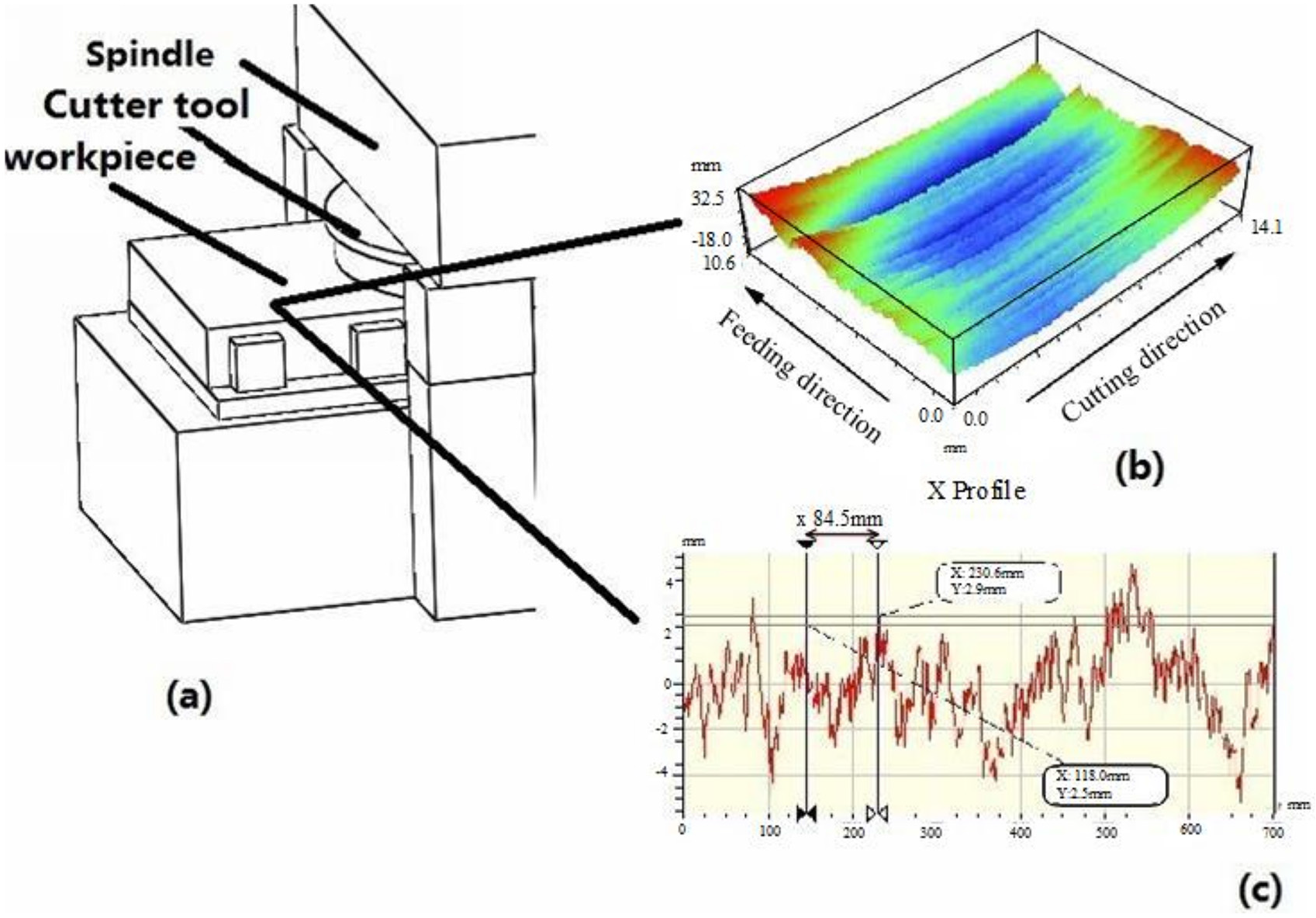
Machining surface: (a) machine tool, (b) 3D surface topography, and (c) 2D surface.
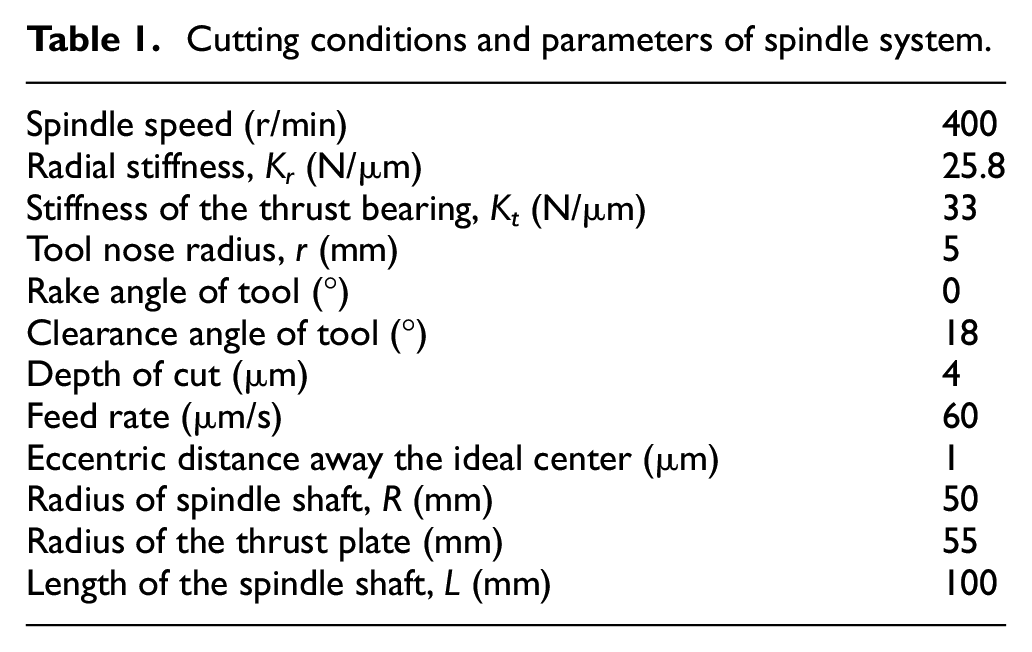
The detailed surface topography in two dimensions is shown in Figure 1(c), in which the spatial period and frequency ripple are obvious. It can be seen that the spatial period is about 84.5 mm, in the range of 40–100 mm, 24 so it belongs to the low-frequency ripple. The corresponding frequency of the surface topography is about f = 2π × L × 6.67 r/s/84.5 mm = 156.15 Hz, the rotation speed of the aerostatic spindle is 400 r/min (i.e. 6.67 r/s), and the distance between the center of the spindle axis and the cutting tool is L = 315 mm. The parameters and conditions of the spindle system are shown in Table 1.
Cutting conditions and parameters of spindle system.
Aerostatic spindle-bearing system
The structure of the aerostatic spindle system
The machining quality of the ultra-precision diamond machining mainly depends on the performance of its components. The aerostatic spindle has the high quality due to the high-stiffness of gas film. Figure 2 shows the structure of the aerostatic spindle in the machine tool, which consists of two radial bearings and thrust bearings. The shaft is connected to two radial plates with sleeve. The shaft and bearings are separated in the radial and thrust direction by the pressurized gas provided by the air compressor. The air is pressurized to the bearing with the air compressor, and a thin film will form between the spindle shaft and the bearing.

Structure of aerostatic spindle: (a) machine tool, (b) spindle, and (c) directions.
The static unbalance model of the aerostatic spindle system
Figure 2(a) shows the structure of the aerostatic spindle machine tool, and we know the cutting tool is clamped on the edge of the big fly-cutting head. When the position of the tool has a deviation with the origin of the spindle system, the unbalance phenomenon will occur. Figure 3 shows the unbalanced state of the aerostatic spindle under the eccentric load in radial (X) and axial (Z) directions. In the figure, the weight of the tool holder system is denoted by Wg, the geometric centroid is G, and the coordinate of the force Wg is (Lw, 0, Lg). Centroid of the spindle system is Os, but its actual rotation center is point Oc. The weight of the spindle system is Ws. The thrust bearing in axial direct in Figure 2 has eight gas chambers, and Fti in Figure 3 denotes the film force for the ith gas chamber. The type of the chamber of the radial bearing (in Figure 2) is double rows (corresponding centers are point Oa and Ob in Figure 3), each row has eight gas chambers, and Fai and Fbi denote the film force for the ith gas chamber. The eccentric degree of the center axis Z depends on the weight of the part Wg. Parameters Kti, Kai, and Kbi are the corresponding stiffness of the ith gas chamber of the aerostatic bearing, and α is the eccentric rotation angle. It is calculated by the following balance equations. Tt is the torque in the axial direction; Ta and Tb are the torques in the radial direction;
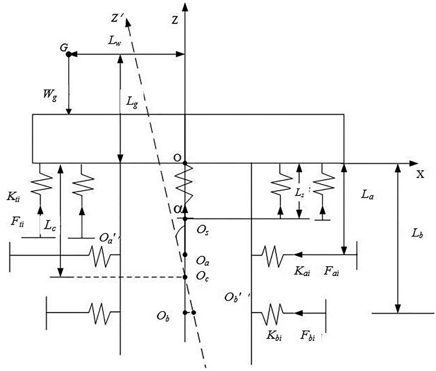
Force balance model of the spindle system.
Through the force and moment balance equations of the spindle system, the result can be obtained as


where Rt is the radius of the thrust bearing, Kt is the stiffness of the thrust bearing, and Kr is the stiffness of the radial bearing.
The above analysis shows that the eccentric degree of the center axis Z of the spindle system depends on the stiffness of the aerostatic bearings in axial and radial directions.
Stiffness and damping of the aerostatic bearing in microscale
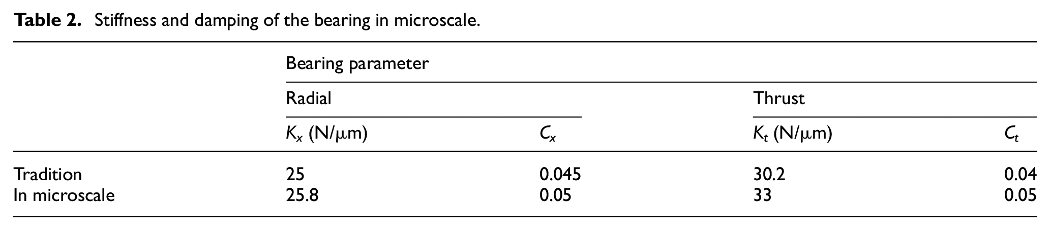
Traditionally, the performance of the aerostatic spindle is calculated only in the macroscale, and the gas film is considered as incompressible. Actually, the gas film between the shaft and bearing is compressible in the machining process, and the gas film is affected by the microscale effect. Based on the microscale effect and the gas lubrication theory, the Reynolds equation for the compressible gas in microscale is established, and the flow factor Q, which embodies the microscale effect, is introduced into the Reynolds equation. Based on this, the stiffness and damping coefficient of the bearing influenced by the microscale effect are calculated. These factors are added to the spring element of the unbalanced spindle model, and the stiffness of the bearing influenced by the microscale effect is obtained. The results are shown in Table 2. From the table, we find that the stiffness and damping values of the bearing in microscale are larger than the value in traditional case. The rate of change of the bearing capacity increases due to the compressibility of the gas. Since the rate of change of the bearing capacity reflects the magnitude of the stiffness, the bearing stiffness in microscale is larger than the traditional case.
Stiffness and damping of the bearing in microscale.
Dynamic unbalance of the spindle system
In order to study the surface topography influenced by the unbalance of the spindle system, the spindle system is simplified, and the dynamic model is shown in Figure 4. In the figure, the shaft is assumed as rigid because the variation of the shaft material is very small relative to the gas film in the bearing clearance. In addition, the rotation errors (including radial, run-out, and tilt errors) of the spindle are decoupled. In the coordinate frame, X, Y, and Z represent the feed direction, the cutting direction, and the axial direction corresponding to the spindle axis, respectively. When the spindle is not eccentric, the position of geometric center is concentric with the bearing center and is defined as the point O. The eccentric mass is M, the distance between the center of the gravity O′ and O is e (ex, ez). Due to the presence of unbalance mass, the spindle axis rotates around the bearing center, generating a deflection θ. ω denotes the rotation speed of the shaft, and Kt and Ct denote the stiffness and damping in axial direction, respectively. Kx and Cx denote the stiffness and damping in radial direction, respectively.

Dynamic model of spindle system.
Basing on the balance conditions in axial and radial directions, respectively, the corresponding motion equations are given by

In the equations, assuming that the original gas film thickness in axial and radial directions are h0x and h0z, respectively, there are ex = εh0x and ez = εh0z and the eccentricity rate is ε. Fr is the load capacity from the gas fluctuation in radial direction, Ft is the corresponding capacity from the gas fluctuation in journal direction, and they depend on the stiffness, damping (calculated in section “Stiffness and damping of the aerostatic bearing in microscale”), and eccentricity of the shaft ex and ez.
With the equations, the vibration response in axial (Z) and radial (X) directions are established, respectively

Dynamic response of spindle system in microscale
In the fly-cutting of the machine tool, the aerostatic spindle may not always remain stable and may produce vibration due to the excitation and micro factors of the gas film. It will cause the small vibration of the cutter tool, and the degree of vibration affects the surface topography of the workpiece. The unstable transient response of the aerostatic spindle system is relative to the surface topography, and this excitation is shown in equation (3) in section “Dynamic unbalance of the spindle system.” The transient response of the translational displacement in radial (X) and axial (Z) directions is simulated as shown in Figure 5, where the displacements in both X- and Z-directions fluctuate with time. The attenuation of the amplitude in the response is decided by the damping of the aerostatic bearings; the enlarged figure shows that the fluctuation is modulated with a relative different frequency envelope. The amplitude and regular of the fluctuation in Z-direction are slightly different with the value in X-direction.
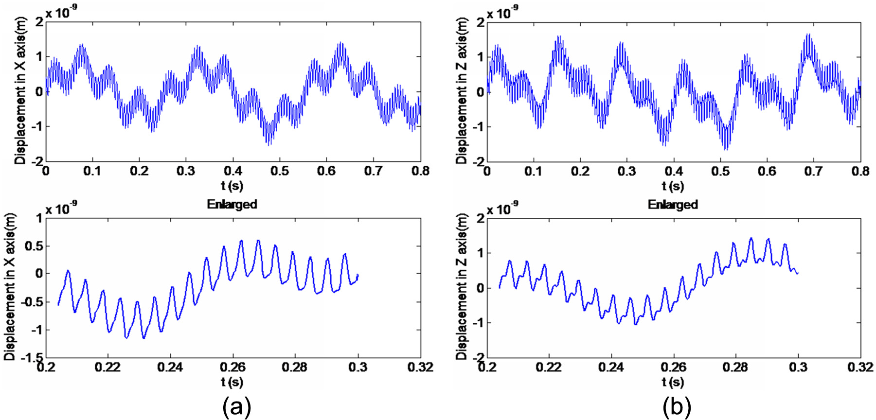
Dynamic transient response: (a) displacement in X-axis and (b) displacement in Z-axis.
In order to analyze the fluctuation feature of the superposition signal, the power spectral density of the simulated data is analyzed, and the results are shown in Figure 6. It shows the frequencies corresponding to the typical wavelengths of the response displacements in X and Z directions in Figure 5, from frequency information, we find the signal consists of one fold frequency of 6.67 Hz (the corresponding rotation speed is 400 r/min), the first natural frequency of 720 Hz and second order frequency of 1450 Hz of the aerostatic spindle. It can be seen from Figure 6 that the rotation and fold frequency are lower than 150 Hz and belong to low frequency fluctuation. Since the spindle motion errors are mainly concentrated in the low frequency, the rotation and fold frequency may come from the spindle movement. From the view of rotor dynamics, it is considered that the low-frequency components are mainly caused by the unbalance response of spindle system, which is usually caused by the defects of spindle stator and rotor and the assembly stress. The fold frequency is mainly caused by the torque fluctuation of the drive motor. Since the fluctuations frequency of gas film is high-frequency signals, the natural frequency of the aerostatic spindle system is from the gas film stiffness and damping. Modal analysis of the aerostatic spindle is analyzed by the finite element method. First, a three-dimensional (3D) computer-aided design (CAD) model is established and imported into ANSYS software. After modeling, the necessary data of material properties are Young’s modulus, Poisson’s ratio, and mass density. The appropriate solid element is used to express the structure of shaft, and spring elements are used to express the thin gas film. Boundary conditions are applied on the meshed model, and finally, modal analysis has been done to obtain the natural frequencies and vibration modes. The natural frequencies of the spindle model by the modal analysis with ANSYS software are shown in Table 3, which is very similar with the results in Figure 6.

Spectrum of the transient response: (a) spectrum of X signal and (b) spectrum of Z signal.
The first five order frequencies of spindle in microscale.

Prediction model of the surface with the parameters of the spindle system
Generation model of the surface induced by the motion error of the spindle
According to the above calculated results, the surface generation worked by the spindle system is described as the following with Weierstrass function, so the generation model of the surface profile is given by

The result of equation (4) in the front part is from the result of equations (1)–(3), and the rear part is from the Weierstrass function. In the Weierstrass function, parameters Lb and Lc are the geometric parameters in Figure 3; parameter g0 is the value in largest scale; parameter λ0 is the profile wavelength in the largest scale; parameter D is the fractal dimension of the surface; parameter γ is the inverse ration in the surface; parameter n is the scale number of the surface. And the solution condition is that the surface error in n scale is equal to the local mean surface error in scale n + 1.
The surface morphology of the workpiece is simulated and analyzed. The result is shown in Figure 7, and the actual machining process is shown in the Figure 1(b). Through the comparison of the actual machining process and the simulation of surface morphology, it is found that the two results are consistent, that is, in the feeding direction, it shows the fold frequency information and the profile with a certain cycle in time domain; in cutting direction, the profile appears ups and downs affected by the excited factors in the machining process. It shows that the simulated result is effective, and it can represent the feature of the actual surface morphology.

The simulated surface topography.
The vibration test of the aerostatic spindle system
The vibration experiments are carried out on a LMS vibration test system, and the test device is shown in Figure 8. In addition, the supply pressure is 0.5 MPa, and the test system contains the BK acceleration sensor in which the sensitivity is 9.6 mV/(m/s2). Several sensors are provided along the circumferential direction of the thrust plate, which will get the more accurate data. When the spindle is in working state, the spindle is knocked along the radial and axial directions by exciting hammer. The vibration data can be obtained by the BK acceleration sensor, then the data will be transferred to the LMS vibration analysis system through the data lines, and the final results can be seen in the screen of the computer. The third-order natural frequency of the spindle (718, 1491 and 4680 Hz) can be seen from the experiment result clearly, and they are close to the simulated result in Table 3.

Test equipment of spindle vibration.
Results and discussion
The actual machining surface topography in Figure 1 and the simulated result in Figure 7 find that the periodicity of the surface of the spindle is different at different rotational speeds of the spindle, but the similar cyclical surface ripple of the workpiece occurs. Surface ripple is formed with a certain period of high and low ups and downs in the process of flying cutting mainly due to the vibration between the workpiece and the spindle system, therefore, the similar cyclical surface ripple of the workpiece is independent of the spindle speed. Figures 9 and 10 give the 3D topography and two-dimensional (2D) profile of the machined surface with different rotation speed of the spindle, and the corresponding frequency features are extracted and analyzed. We find that there were two high amplitudes, and the corresponding frequencies could be found in the spectrum, which is decided by the rotation speed and the distance between two peaks in coordinate axis in the surface profile. In Figure 9, the rotation speed is 400 r/min, and the distance between two peaks is 78.9 mm in Figure 9(b). Therefore, the corresponding frequency is f = 2π × L × 400 r/min/60 s/78.9 mm = 167.2 Hz, where L denotes the distance between the center axis of the spindle and cutting tool, and it is 315 mm. Another frequency 721 Hz is relative to natural frequency of spindle in Figure 9(b). There is no change of other machining conditions and parameters in Figure 10. Generally, when the rotation speed decreases, the distance between two peaks should be increased. In Figure 10(b), the distance between two peaks is decreased to 63.6 mm since the rotation speed of the spindle decreases to 300 r/min. This phenomenon is different from the above research, which indicates that aerostatic spindle system is relative to the results. The gas fluctuation enhances the vibration of the spindle and leads to changes in the surface topography. It is found that f = 718 Hz occurs in Figures 9(d) and 10(d), which corresponds to the high-fluctuation amplitude and affects the machining surface topography greatly. Since it is very close to the natural frequency in Table 3 in section “Dynamic response of spindle system in microscale,” this indicates that corresponding to the natural frequency of spindle. The natural frequency of the spindle is independent of the spindle speed, which is related to the fluctuation of the film. This shows that when the spindle does not work and only the air compressor works, the fluctuation of the aerostatic spindle will occur, and the natural frequency also exists.
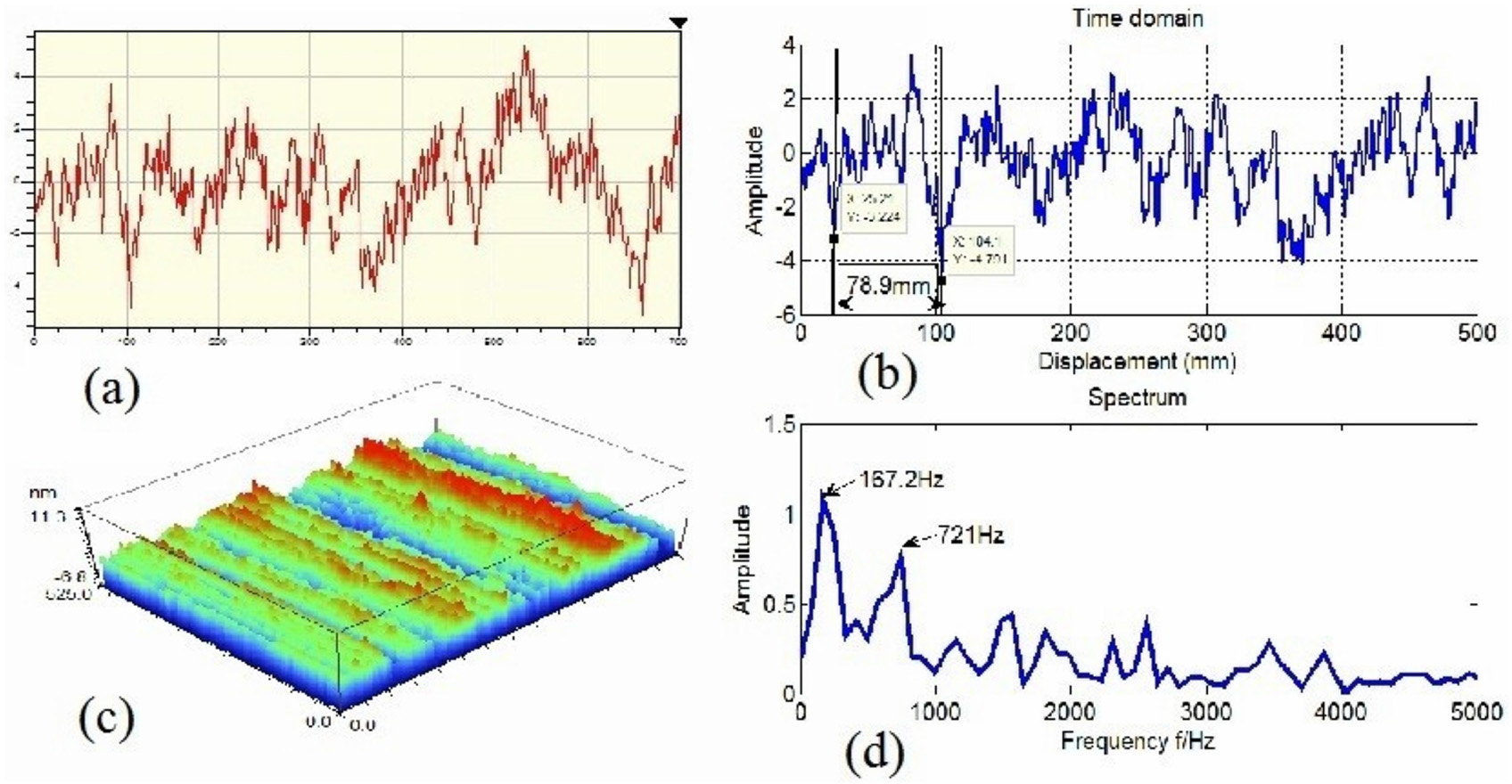
Surface result with rotation speed 400 r/min: (a) 2D surface topography, (b) surface topography in time domain, (c) 3D surface topography, and (d) surface topography in frequency domain.

Surface result with rotation speed 300 r/min: (a) 2D surface topography, (b) surface topography in time domain, (c) 3D surface topography, and (d) surface topography in frequency domain.
Conclusion
The effect of the gas fluctuation of the aerostatic spindle on the surface generation is deeply analyzed in this study. Dynamic model of spindle system has been presented to investigate the effect of the micro factor of the gas film on the stiffness, rotation error, and modal information of the aerostatic spindle system. For the analysis of the machining surface topography, the fluctuation of the spindle has a significant effect on machining accuracy in ultra-precision fly-cutting. Through the calculated model and the analysis of the machining results, we get the following conclusions:
The dynamic model of the aerostatic spindle is established, which considers the variation of the stiffness and damping in microscale. The gas fluctuation is found during the rotation of the spindle, and the transient response and frequency information are analyzed.
The surface generation model is proposed, and the influence of the rotation speed on the surface topography is analyzed. From the machining result with different speeds of the spindle, we find the circle of the surface is different.
Different from the normal case, with the increase of the rotation speed of the spindle, the periodic wavelength is increased. It can be found that the performance of the gas film of the spindle has relative with the forming of the surface and it is not negligible.
The natural frequency of the spindle system appears in the spectrum analysis of the machining surface, which indicates that machining result is also affected by the gas fluctuation.
These can take theoretical basis for the design and machining process of machine tool.
Footnotes
Handling Editor: Seung-Bok Choi
Declaration of conflicting interests
The author(s) declared no potential conflicts of interest with respect to the research, authorship, and/or publication of this article.
Funding
The author(s) disclosed receipt of the following financial support for the research, authorship, and/or publication of this article: This research was funded by the National Natural Science Foundation of China grant no. 51475010, Beijing Nova program (Z161100004916156), Natural Science Foundation of Beijing Municipality grant no. 3142005, and Ultra-precision Machining Technology Key Laboratory Major Fund of China Academy of Engineering Physics (ZZ14002).