
Abstract
In this article, a decentralized control strategy is presented for harmonic drive–based modular and reconfigurable robots with uncertain environment contact. Unlike conventional methods that rely on robot–environment contact model or force/torque sensing, this article addresses the problem of controlling modular and reconfigurable robots in contact with uncertain environment using only encoder data of each joint module. By employing a control-oriented harmonic drive model, the dynamic model of modular and reconfigurable robot is formulated as a synthesis of interconnected subsystems, in which the interconnected joint couplings are with small magnitudes. Based on the integral sliding mode control technique and the adaptive super-twisting algorithm, the decentralized controller is designed to compensate model uncertainty in which the up-bound is unknown. The stability of the modular and reconfigurable robot system is proved using Lyapunov theory. Finally, simulations are conducted for 2-degree-of-freedom modular and reconfigurable robots with different configurations under the situations of dynamic contact and collision to investigate the advantage of the proposed approach.
Keywords
Introduction
Modular and reconfigurable robots (MRRs) comprise the robot modules, which contain power supplies, processing systems, actuators, and sensors. These modules are assembled to desirable configurations with standard interfaces to satisfy the needs of various tasks with a complex working environment. Therefore, the MRRs are often utilized in unknown and dangerous environments, for example, space exploration, disaster assistance, and high-/low-temperature operations. Besides, in the face of a complex and uncertain environment, MRRs need suitable control systems to provide stability and accuracy after reconfigurations.
Besides the property of reconfigurability, an ideal MRR system should be designed to possess the ability of physically interacting with the external environment, for example, the dynamic contact and collision with time-varying environment constraint, and ensuring the accuracy of control performance in trajectory tracking. Some insightful investigations are presented for addressing the problems of robust stabilization and uncertainty compensation of mechatronic systems based on a novel robust integral of the sign of the error (RISE) feedback method1,2 and extended state observer (ESO).3,4 Besides, to tackle the concerns of raising interaction stability, numerous researches have focused on developing robot–environment contact models5,6 which are implemented for investigating the cases of position control7,8 and force control.9,10 However, the limitation of the existing contact model–based control methods is that it relies on the exact knowledge of the robot and environment dynamics. Indeed, MRRs are always designed for satisfying various task requirements under uncertain environments; this means the dynamic model of MRRs will be changed under different configurations, and the contact model is also difficult to be obtained. To avoid using the enclosed forms of dynamic models and contact models, and seeking out high-performance control for MRRs, joint torque feedback techniques are attached with attentions of both robotic researchers and industrial manufacturers. Several successful applications of direct joint torque sensing techniques are published in the literatures.11–13 However, using joint torque sensor, measurements are known directly with many drawbacks and may jeopardize the simplicity, reliability, and mechanical ruggedness of the modular robots. For one thing, the strain gauges, which are the most important components of the torque sensors, are known with intensive sensitivity to peripheral temperature variations; for another thing, the sensor data are contaminated with too much noise and unstable states, which are caused by the narrow bandwidth of the torque information. Therefore, an excellent control system for an MRR with uncertain environment contact should be able to eliminate the needs of contact models and force/torque sensing, and it relies only on encoder data of each joint module.
A significant property of MRRs is that the robot modules can be appended, removed, and replaced optionally without the requirement of readjusting the gains and parameters of the controllers in other modules, so that the MRRs can be reassembled to satisfy different requirements of various tasks. Decentralized control is a promising strategy in particular for implementing the control system of MRRs. The decentralized control design always arises from many complex conditions where there exist physical restrictions on information interchange among the subsystems for which there is an insufficient capacity of possessing a centralized controller. Furthermore, a decentralized control architecture based on local modular information not only provides the flexibility of structure, which is applicative for all the robot configurations, but also decrease the computation consumptions that are critical for the real-time operation of the MRR systems. A number of researches have been made toward the decentralized control method for MRRs. Based on generic locomotion algorithm, a decentralized control method is presented for a lattice-based reconfigurable robot. 14 A joint torque sensing–based decentralized control method is investigated to address the problems of fault detection and tolerant control of MRRs. 15 A decentralized reconfiguration strategy is proposed for MRRs assembling furniture-like structures from Roombots metamodules. 16 A decentralized robust control algorithm is presented for MRRs with harmonic drive transmission based on backstepping technique and Lyapunov theory. 17 In our previous researches, a stable decentralized control method is proposed for MRRs by employing adaptive fuzzy algorithm and sliding mode control technique for satisfying the conception of modular design; 18 building on these results, we also proposed a reinforcement learning-based decentralized optimal control method 19 and a decentralized integral nested sliding mode control scheme for MRRs under the situation of time-varying constraint. 20 However, the main disadvantage of the above-mentioned methods is that the interconnected joint couplings, which include the Coriolis, centripetal torques, gravitational torques, and so on regarding all joint modules, are simply treated as external disturbances or model uncertainties with known up-bounds. Unfortunately, the magnitudes of the interconnected couplings between the joints in these strategies are very large, so that the decentralized compensating controllers, which are designed to handle the uncertainties, should be with higher control gains, and this may cause controller chattering and further spoiling the performance of the controllers. Besides, to the best of the authors’ knowledge, there are few types of research that focus on investigating the decentralized control strategy of the MRRs under uncertain environment contact. Therefore, it is meaningful to devise an appropriate decentralized control method for MRRs, particularly under the situations of uncertain environment contact, and the controllers should be with the capability of effectively compensating the interconnected joint couplings and reducing the chattering effect of the controllers.
In this article, we present a decentralized control strategy for harmonic drive–based MRRs with uncertain environment contact. First, by employing a control-oriented harmonic drive model that considers the compliance of both the wave generator and flexspline, the dynamic model of the MRR is formulated as a synthesis of interconnected subsystems, in which the magnitudes of the interconnected couplings between the joints are decreased significantly. Second, based on the integral sliding mode control (ISMC) technique21,22 and the adaptive super-twisting algorithm (ASTA),23,24 a decentralized controller is proposed which utilizes only encoder data of each isolate joint module to compensate model uncertainty and to reduce the chattering effect of the controller, as well as the stability of the closed-loop MRR system is proved using Lyapunov theory. Finally, simulations are conducted for 2-degree-of-freedom (DOF) MRRs with different configurations under the situations of dynamic contact and collision to investigate the advantage of the proposed approach.
The main contributions of this article can be summarized as follows:
Unlike conventional methods that rely on robot–environment contact model or force/torque sensing, this article focuses on addressing the trajectory tracking control problems of MRRs with uncertain environment contact that uses only encoder data on the motor side and link side of each isolate joint module, and the joint modules can be used to construct various configurations without the requirement of readjusting the control gains and parameters.
In this article, we consider the MRRs are with model uncertainties, which contain friction modeling error and uncompensated interconnected joint couplings, and then model uncertainties are compensated under ASTA-based ISMC, which can reduce the chattering effect of the controller and adjust the control gains and parameters adaptively while the up-bounds of the uncertainties are unknown.
The remainder of this article is organized as follows: section “Model and problem formulation” outlines the dynamic model of harmonic drive–based MRR. The proposed decentralized control strategy is presented in section “Decentralized ISMC design based on ASTA,” and the simulations are illustrated in section “Simulations.” Concluding remarks are given in section “Conclusion.”
Model and problem formulation
In this section, we formulated the dynamic model of harmonic drive–based MRRs with uncertain environment contact. Two parts are included in this section; in the first part, a control-oriented harmonic drive model is constructed which considers both wave generator compliance and flexspline compliance, and in the second part, the dynamic model of MRR with uncertain environment contact is formulated based on the harmonic drive model.
Harmonic drive model
Considering an MRR comprising n modules, and each module is integrated with a harmonic drive–based rotary joint. By referring to the literatures,25,26 which are performed for analytically describing the structural property of harmonic drive, one concludes the following ideal kinematic relationship

where

where
However, the experimental measurements of the kinematic relationship between the wave generator and the flexspline provided in the literatures27,28 clearly show that the link-side position measurement is not linearly related to the motor-side position measurement. The causation of this nonlinearity is due to the compliance in the harmonic drive components, and the kinematic error may attribute to gear meshing and machining errors. Given this ideal kinematic relationship which describes the motion and force constraints present in harmonic drives, the remaining effects can be incorporated by introducing compliance and kinematic error properties.
By combining the link-side and motor-side position measurements, the torsional compliance of the flexspline and wave generator is described as follows

where

By adding and subtracting the terms
where the kinematic error of the harmonic drive torsional angle
To compensate the kinematic error

where
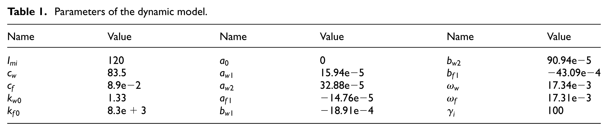
Parameters of the dynamic model.
According to the typical stiffness property of a harmonic drive, which is proposed by Zhang et al.,
30
it is obvious that the local elastic coefficient increases as the flexspline torque increases. Therefore, one can define the local elastic coefficient of the flexspline

Considering the symmetric performance of harmonic drive stiffness, the local elastic coefficient

where

Besides, the deformation range of harmonic drive drops to zero sharply at rated torque, which implies that the wave generator stiffness increases sharply. For the purpose of replicating the hysteresis shape of this stiffness property, the local elastic coefficient of wave generator is modeled as

where

where

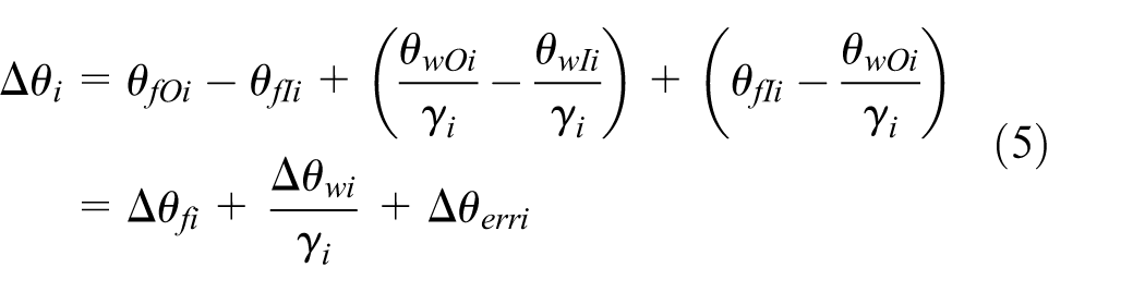
Substituting equations (10) and (12) into equation (5), define the total torsional angle of a harmonic drive as follows

Deforming the equation above, one obtains that
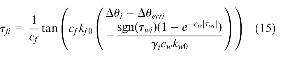
In equation (15),
Dynamic model of harmonic drive–based MRR
According to the torque sensing–based robot manipulator dynamic modeling method proposed by Imura et al., 31 and the encoder data–based flexspline torque estimation method given in equation (15), in this part, the dynamic model of harmonic drive–based MRR system is formulated as a synthesis of interconnected subsystems, in which the ith subsystem dynamic model is formulated as follows

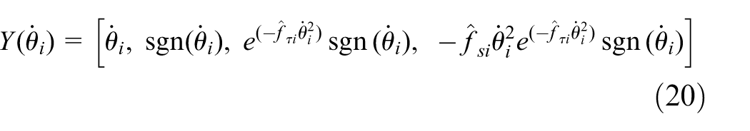
where
For the friction torque term

where

where

and
Besides, for terms


In equations (21) and (22), one obtains the relationships of
Then, on the basis of the decomposition scheme of model uncertainty, which is represented by Liu and Goldenberg,
35
the model uncertain terms of

where superscripts c and v denote the constant and variable parts, respectively. By analyzing the parameters and variables in the dynamic model equation (16) and the uncertain terms in equation (23), one obtains that model uncertainties
Constant parametric uncertainties, which exist in terms of
Variable parametric uncertainties, which exist in terms of
Nonparametric model uncertainty contains the nonparametric friction term
Substituting equations (21) and (22) into equation (16), one can rewrite the dynamic model of ith subsystem as follows

where
Define the system state vector

The control object of this article is to design a decentralized control strategy for harmonic drive–based MRR with uncertain environment contact that uses only encoder data of each joint module and to make the joints and end-effector follow the desired trajectories.
Decentralized ISMC design based on ASTA
According to the dynamic model of harmonic drive–based MRR in equation (16) and the state space in equation (25), in this section, a decentralized ISMC method is proposed based on ASTA to compensate model uncertainty in which the up-bound is unknown and to reduce controller chattering.
Let the desired position, velocity, and acceleration of the ith joint be

where

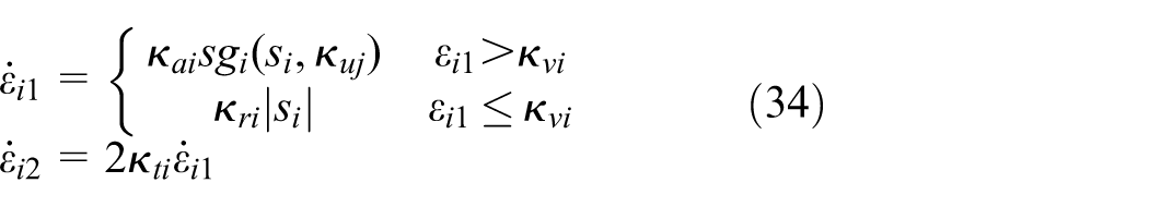
where
Remark 1
The nonlinear potential function
Combining equations (16), (18), (21), and (22) with equation (26), the time derivative of

In equation (28), we can rewrite the decentralized control law
First, design the control law

where
Second, design the control law

where the continuous functions

where
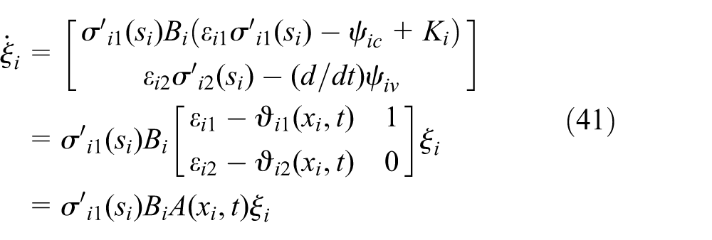
Substituting equations (29) and (30) into equation (28), the time derivative of sliding surface

Then one can design the ASTA-based control law

where
where
Combining equation (29) with equation (33), the proposed decentralized control law

Theorem
Consider an MRR with uncertain environment contact comprising n modules, with the dynamic model of the ith subsystem as given in equation (16) and model uncertainties as in equations (19), (21), and (22) with unknown up-bounds. The trajectory tracking errors of each robotic joint are bounded under the decentralized control law designed by equation (35).
Proof
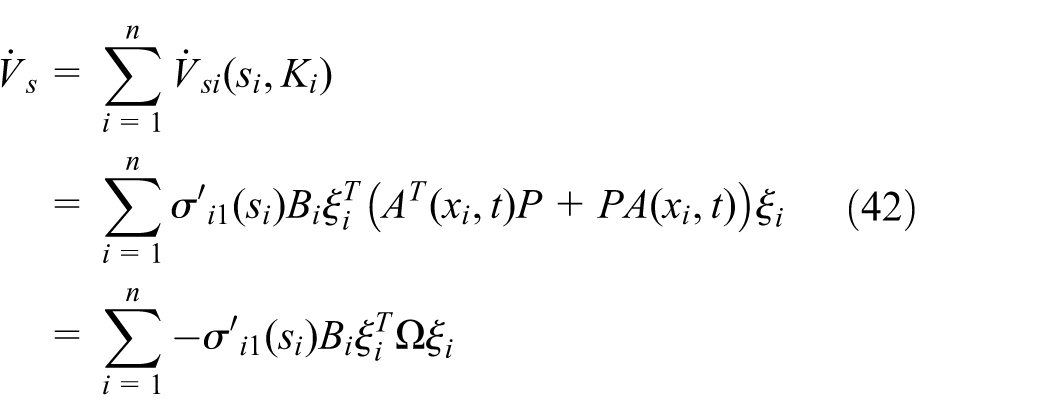
To prove the theorem, at first, we can reformulate the time derivative of the sliding surface in equation (32) as follows

where

Consider the Lyapunov function candidate as the following form

First, define one part of Lyapunov function candidate

where

where
So that the time derivative of
where
and

In equation (43), note that the following three relations are satisfied: (a)

Since
where

where

From equations (44) to (47), one obtains
where

Second, define the other part of Lyapunov function candidate
where

where

According to equations (38) and (52), one can conclude the following inequality relationship

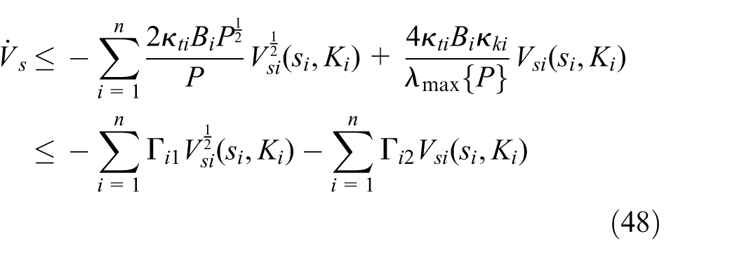
where
For the case of
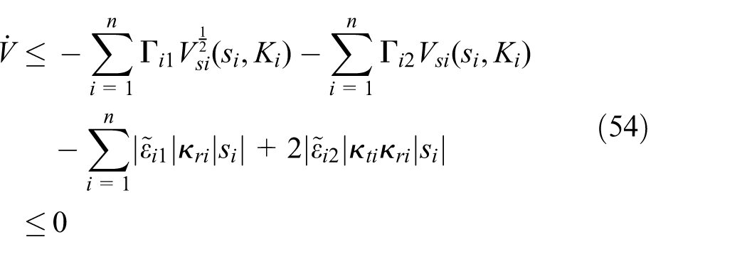
Therefore, according to equations (53) and (54), on the basis of Lyapunov theory, the MRR system is stable. This concludes the proof of the theorem.
Simulations
Simulation setup
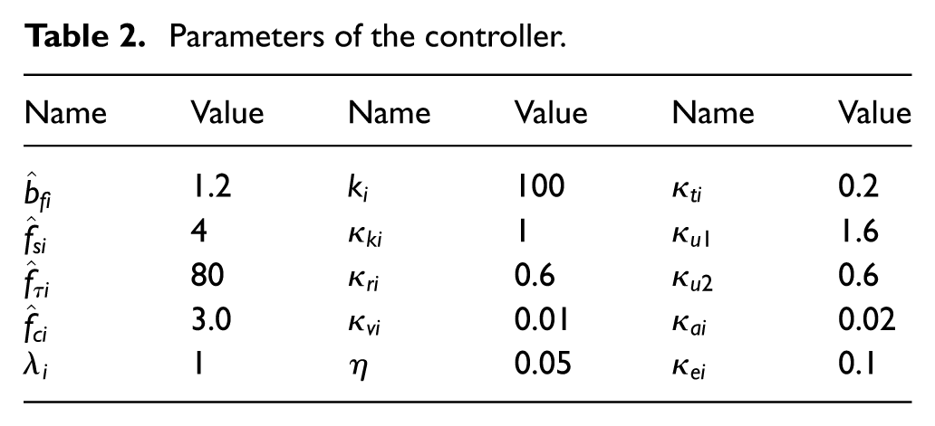
To verify the advantage of the proposed decentralized control method, in this section, two 2-DOF MRRs with uncertain environment contact are used to conduct the simulations. The simulation setup of the MRRs is illustrated in Figure 1, where l1, l2, and l3 denote the length of the links, respectively, and l4 denotes the length between the base module and the time-varying constraint. By referring to our previous work, 19 the friction model parameters, which are used to conduct the simulations, are given as follows

and the other parameters of the dynamic model and controller are given in Tables 1 and 2, respectively. The initial positions of the two MRRs are chosen as
Configuration A

Configuration B
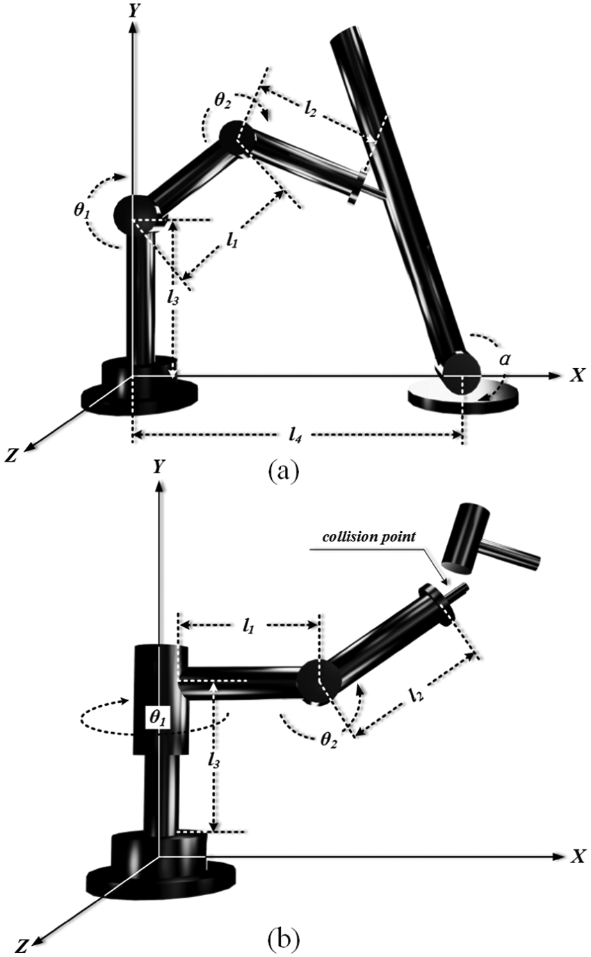
Simulation setup of the MRRs with external environment constraint and collision: (a) configuration A and (b) configuration B.
Parameters of the controller.
Two types of external environment contacts are considered in the simulations including continuous time-varying environment constraint (configuration A) and collision at random time point (configuration B). The environment constraint of configuration A is considered as a kind of column, with length of 0.5 m and mass of 4 kg, and rotating as a time-varying angle variable

For configuration B, the constant collision force of 50 N is upright exerted at the end-effector at the time points of 5 and 6 s. The implemented time-varying constrained force and collision force curves are given in Figure 2. Note that the contact force and the collision force information are used only for setting up the the simulations but the control designs, so that for the controllers of the MRR systems, the environment contact forces are unknown all the time.
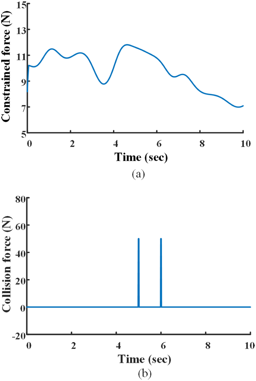
Environment contact force curves: (a) time-varying constraint force of configuration A and (b) collision force of configuration B.
Simulation results
The simulation results are obtained by employing the constructed simulation setup of the MRRs with different configurations to investigate the variation in position tracking, position error, flexspline torque, and control torque of each joint module, as well as the performance of position tracking of the end-effectors. Two kinds of control method including the conventional super-twisting algorithm (STA)-based sliding mode control (SMC)36,37 and the proposed ASTA-based ISMC are implemented to compare the control performance and to verify the advance of the proposed method in this article.
Joint position tracking and position error
Figures 3–6 illustrate the joint trajectory tracking curves and joint position error curves under different MRR configurations using STA-based SMC and ASTA-based ISMC. From Figures 3 and 4, we obtain that the desired trajectories are tracked effectively with the time-varying constraint under both STA-based SMC and ASTA-based ISMC. However, when the collision force is exerted at the end-effector of the MRR, a 0.2-s time interval is required for STA-based SMC to restabilize the robot joints. Besides, the robot joints can be restabilized within only 0.1 s under ASTA-based ISMC. From Figures 5(a) and 6(a), we observe that the convergence of the position error is achieved under conventional STA-based SMC, and the maximum position error values of each joint are close to 4.0 e−3 rad. Besides, since the control gains and parameters cannot be adjusted adaptively when the up-bound of the uncertainty is unknown, the periodic position error is relatively obvious under this control. From the simulation results in Figures 5(b) and 6(b), one can conclude that the tracking performances of joint positions are improved obviously since model uncertainties have been compensated accurately under ASTA-based ISMC, and the sliding manifold is reached in less than 0.2 s; after that, the MRR system is in sliding manifold.

Joint trajectory tracking curves of configuration A: (a) STA-based SMC and (b) ASTA-based ISMC.

Joint trajectory tracking curves of configuration B: (a) STA-based SMC and (b) ASTA-based ISMC.

Joint position error curves of configuration A: (a) STA-based SMC and (b) ASTA-based ISMC.
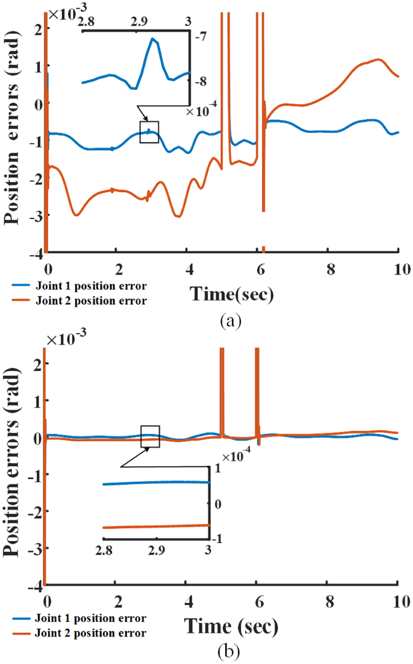
Joint position error curves of configuration B: (a) STA-based SMC and (b) ASTA-based ISMC.
Flexspline torque
Figures 7 and 8 show the flexspline torque curves of each joint module, which are estimated using the motor-side and link-side position measurements. From the simulation results, one obtains that the flexspline torques of each joint are estimated appropriately under the situations of external environment contact and collision, and this may eliminate the needs of joint torque sensors, which can hardly withstand the instantaneous collisions. However, in Figures 7(a) and 8(a), one observes that the estimated flexspline torques are with the chattering effects obviously under STA-based SMC, because the chattered position measurements are employed in the harmonic drive model to estimate the flexspline torques. Moreover, improved simulation results of the joint flexspline torques are illustrated in Figures 7(b) and 8(b), since the chattering effects of the flexspline torques are reduced obviously under ASTA-based ISMC. Besides, the joint flexspline torque curves are smoother than the former ones with unknown environment contact, especially in the intervals of the initial time and collision time.

Flexspline torque curves of configuration A: (a) STA-based SMC and (b) ASTA-based ISMC.

Flexspline torque curves of configuration B: (a) STA-based SMC and (b) ASTA-based ISMC.
Control torque
Figures 9 and 10 show the control torque curves of each joint under STA-based SMC and ASTA-based ISMC, respectively. In Figures 9(a) and 10(a), one concludes that the desired sliding surface is reached within 0.2 s under STA-based SMC, and the chattering effects of the control torques are obvious relatively because the switching nonideality causes a high-frequency oscillation to appear in the neighborhood of the sliding manifold; moreover, another source of controller chattering is that the flexspline torques, which are used for controller design, are also with chattering effects. Besides, in Figures 9(b) and 10(b), one observes that the desired sliding surface is reached in the initial time and the control torque curves are smoother obviously than the former ones since the chattering effects are reduced effectively under ASTA-based ISMC.
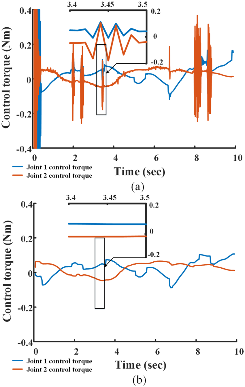
Control torque curves of configuration A: (a) STA-based SMC and (b) ASTA-based ISMC.

Control torque curves of configuration B: (a) STA-based SMC and (b) ASTA-based ISMC.
Three-dimensional end-effector trajectory tracking
Figure 11 shows the three-dimensional (3D) end-effector trajectory tracking curves under different configurations of MRR with dynamic contact and collision under ASTA-based ISMC. From the simulation results, one obtains that when the external environment contact and collision force are exerted on the end-effector of an MRR with different configurations, the end-effector desired trajectories can be tracked accurately under the proposed ASTA-based ISMC.

3D end-effector trajectory tracking curves under ASTA-based ISMC: (a) configuration A and (b) configuration B.
From the aforementioned simulation results, we can conclude that the proposed decentralized controller can provide accuracy and stability for MRRs to satisfy the requirements of various tasks with complex working environments.
Conclusion
This article focuses on investigating harmonic drive–based MRRs with uncertain environment contact and addresses the problems of trajectory tracking control using only encoder data. The dynamic model of an MRR is formulated based on a control-oriented harmonic drive model, and the magnitudes of the interconnected joint couplings are decreased significantly in this model. A decentralized control strategy is proposed based on ISMC and ASTA to compensate model uncertainty in which the up-bound is unknown and to reduce the chattering effect. The stability of the MRR system is proved by Lyapunov theory. Finally, simulations are performed to verify the advantage of the proposed method.
Footnotes
Academic Editor: Nasim Ullah
Declaration of conflicting interests
The author(s) declared no potential conflicts of interest with respect to the research, authorship, and/or publication of this article.
Funding
The author(s) disclosed receipt of the following financial support for the research, authorship, and/or publication of this article: This work was supported by the National Natural Science Foundation of China (grant no. 61374051), the State Key Laboratory of Management and Control for Complex Systems (grant no. 20150102), and the Scientific Technological Development Plan Project in Jilin Province of China (grant nos 20160520013JH, 20160414033GH, and 20150520112JH).